2005 NISSAN NAVARA check oil
[x] Cancel search: check oilPage 911 of 3171

DI-1
DRIVER INFORMATION SYSTEM
K ELECTRICAL
CONTENTS
C
D
E
F
G
H
I
J
L
M
SECTIONDI
A
B
DI
DRIVER INFORMATION SYSTEM
PRECAUTION ............................................................ 3
Precautions for Supplemental Restraint System
(SRS)“AIRBAG”and“SEATBELTPRE-TEN-
SIONER” .................................................................. 3
Wiring Diagrams and Trouble Diagnosis .................. 3
COMBINATION METERS ........................................... 4
System Description .................................................. 4
UNIFIED METER CONTROL UNIT ...................... 4
POWER SUPPLY AND GROUND CIRCUIT ........ 4
SPEEDOMETER ................................................... 4
TACHOMETER ..................................................... 4
WATER TEMPERATURE GAUGE ........................ 4
FUEL GAUGE ....................................................... 5
ODO/TRIP METER ............................................... 5
TRIP COMPUTER ................................................ 5
ENGINE OIL MAINTENANCE INFORMATION..... 6
METER ILLUMINATION CONTROL ..................... 6
CLOCK .................................................................. 6
AMBIENT AIR TEMPERATURE INDICATION ...... 6
Component Parts and Harness Connector Location..... 7
Arrangement of Combination Meter ......................... 8
Internal Circuit .......................................................... 9
Wiring Diagram — METER — ................................ 10
Terminals and Reference Value for Combination
Meter ...................................................................... 12
Self-Diagnosis Mode of Combination Meter ........... 13
FUNCTION .......................................................... 13
OPERATION PROCEDURE ............................... 13
TEST ITEM ......................................................... 13
CONSULT-II Function (METER) ............................. 15
CONSULT-II BASIC OPERATION ....................... 15
SELF-DIAG RESULTS ........................................ 16
DATA MONITOR ................................................. 17
Trouble Diagnosis .................................................. 18
HOW TO PERFORM TROUBLE DIAGNOSIS ... 18
PRELIMINARY CHECK ...................................... 19
Symptom Chart ...................................................... 19
Power Supply and Ground Circuit Inspection ........ 19
Vehicle Speed Signal Inspection ............................ 20
Engine Speed Signal Inspection ............................ 21Engine Coolant Temperature Signal Inspection ..... 21
Fuel Level Sensor Signal Inspection ...................... 22
Ambient Sensor Signal Inspection .......................... 24
Fuel Gauge Fluctuates, Indicates Wrong Value, or
Varies ...................................................................... 25
Fuel Gauge Does Not Move to Full position ........... 25
DTC [U1000] CAN Communication Circuit ............. 26
DTC [B2205] Vehicle Speed Circuit ........................ 26
Electrical Components Inspection .......................... 27
FUEL LEVEL SENSOR UNIT CHECK ................ 27
AMBIENT SENSOR CHECK ............................... 27
Removal and Installation of Combination Meter ..... 27
WARNING LAMPS .................................................... 28
System Description ................................................. 28
OIL PRESSURE WARNING LAMP ..................... 28
Component Parts and Harness Connector Location... 28
Schematic ............................................................... 29
Wiring Diagram — WARN — .................................. 30
A/T MODELS ....................................................... 30
M/T MODELS ...................................................... 37
Oil Pressure Warning Lamp Stays Off (Ignition
Switch ON) ............................................................. 44
Oil Pressure Warning Lamp Does Not Turn Off (Oil
Pressure Is Normal) ................................................ 45
Oil Pressure Warning Lamp Keeps Blinking (Oil
Level Is Normal) ..................................................... 46
Component Inspection ............................................ 47
OIL PRESSURE SWITCH ................................... 47
OIL LEVEL SENSOR .......................................... 47
A/T INDICATOR ........................................................ 48
System Description ................................................. 48
Wiring Diagram — AT/IND — ................................. 49
A/T Indicator Does Not Illuminate ........................... 50
WARNING CHIME ..................................................... 51
System Description ................................................. 51
POWER SUPPLY AND GROUND CIRCUIT ....... 51
LIGHT WARNING CHIME ................................... 51
KEY REMINDER WARNING CHIME .................. 51
LOW-FUEL WARNING CHIME ........................... 51
SEAT BELT WARNING CHIME ........................... 52
Page 914 of 3171

DI-4
COMBINATION METERS
COMBINATION METERS
PFP:24814
System DescriptionEKS00L8E
UNIFIED METER CONTROL UNIT
lSpeedometer, odo/trip meter, tachometer, fuel gauge and water temperature gauge are controlled by the
unified meter control unit, which is built into the combination meter.
lWarning lamp and indicator lamp are controlled by signals drawn from each unit with CAN communication
and components connected directly to the combination meter.
lOdo/trip meter display is included in the combination meter, which displays odometer, trip-meter, vehicle
information (trip computer, engine oil maintenance information)
*and A/T position*.
*: Vehicles with each system only.
lClock display is included in the combination meter, which displays current time, ambient air temperature*
and 4WD indicator*.
*: Vehicles with each system only.
lUnified meter control unit corresponds a CONSULT-II function (self-diagnosis results and data monitor).
lThe following items can be checked during self-diagnosis mode.
–Sweep of gauges pointer
–Present gauge values
–Odo/trip meter display and clock display segments
–Condition of warning lamps/indicator lamps controlled by unified meter control unit
–Battery voltage
–Driver's seat belt buckle switch status
–CPU status of unified meter control unit
POWER SUPPLY AND GROUND CIRCUIT
Power is supplied at all times
lthrough 10A fuse [No.19, located in the fuse block (J/B)]
lto combination meter terminal 3.
With the ignition switch in the ON or START position, power is supplied
lthrough 10A fuse [No.14, located in the fuse block (J/B)]
lto combination meter terminal 16.
Ground is supplied
lto combination meter terminals 13 and 23
lthrough grounds M21, M80 and M83.
SPEEDOMETER
The speedometer indicates the vehicle speed.
lABS actuator and electric unit (control unit) converses a pulse signal from wheel sensor to vehicle speed
signal, and transmits vehicle speed signal to combination meter with CAN communication.
lCombination meter converses the vehicle speed signal to angle signal, and commands to speedometer.
TACHOMETER
The tachometer indicates engine speed in revolutions per minute (rpm).
lECM converses a signal from crank position sensor to engine speed signal, and transmits to combination
meter with CAN communication.
lCombination meter converses the engine speed signal to angle signal, and commands to tachometer.
WATER TEMPERATURE GAUGE
The water temperature gauge indicates the engine coolant temperature.
lECM converses a signal from water temperature sensor to engine coolant temperature signal, and trans-
mits to combination meter with CAN communication.
lCombination meter converses the engine coolant temperature signal to angle signal, and commands to
water temperature gauge.
Page 929 of 3171
COMBINATION METERS
DI-19
C
D
E
F
G
H
I
J
L
MA
B
DI
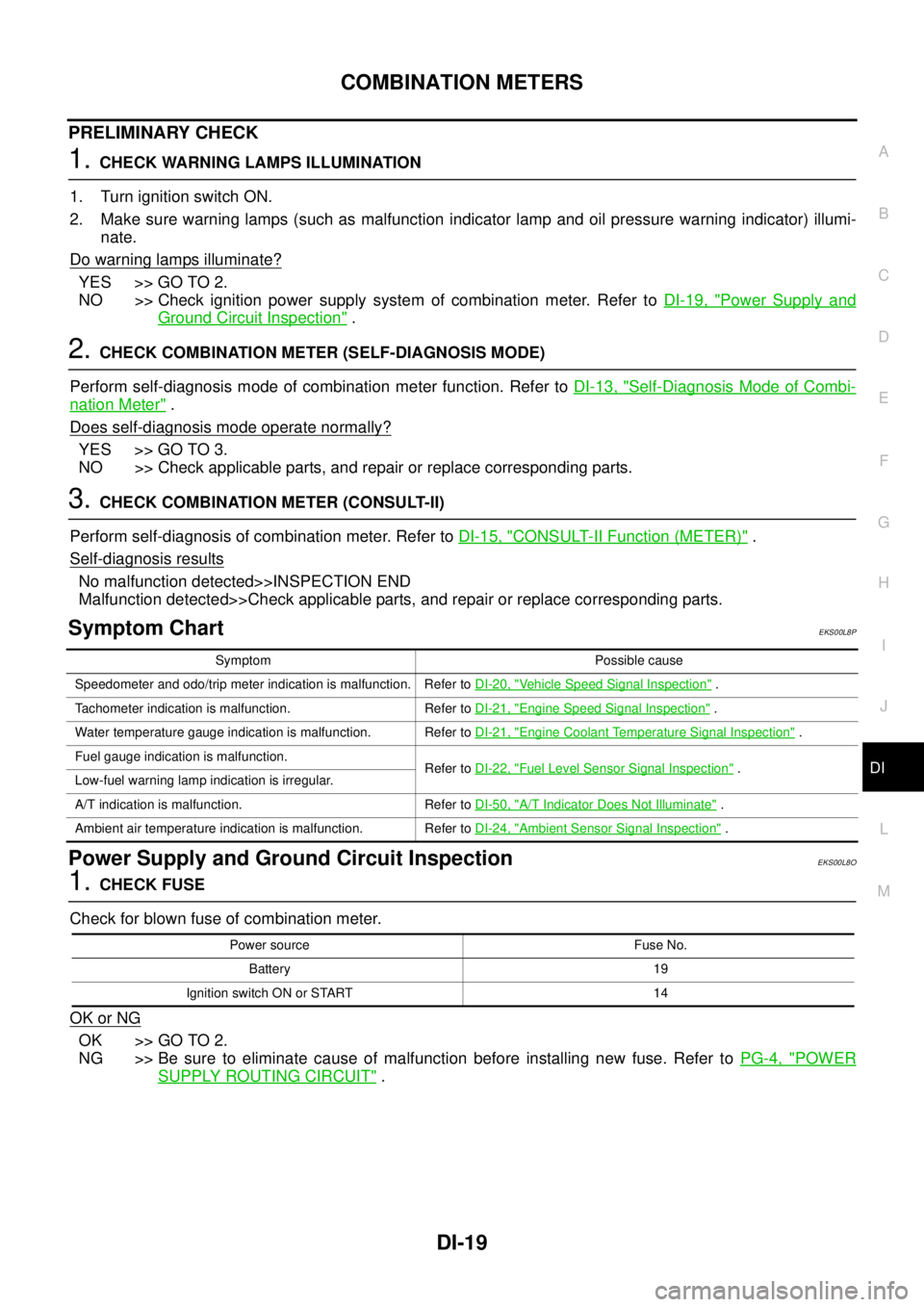
PRELIMINARY CHECK
1.CHECK WARNING LAMPS ILLUMINATION
1. Turn ignition switch ON.
2. Make sure warning lamps (such as malfunction indicator lamp and oil pressure warning indicator) illumi-
nate.
Do warning lamps illuminate?
YES >> GO TO 2.
NO >> Check ignition power supply system of combination meter. Refer toDI-19, "
Power Supply and
Ground Circuit Inspection".
2.CHECK COMBINATION METER (SELF-DIAGNOSIS MODE)
Perform self-diagnosis mode of combination meter function. Refer toDI-13, "
Self-Diagnosis Mode of Combi-
nation Meter".
Does self-diagnosis mode operate normally?
YES >> GO TO 3.
NO >> Check applicable parts, and repair or replace corresponding parts.
3.CHECK COMBINATION METER (CONSULT-II)
Perform self-diagnosis of combination meter. Refer toDI-15, "
CONSULT-II Function (METER)".
Self-diagnosis results
No malfunction detected>>INSPECTION END
Malfunction detected>>Check applicable parts, and repair or replace corresponding parts.
Symptom ChartEKS00L8P
Power Supply and Ground Circuit InspectionEKS00L8O
1.CHECK FUSE
Check for blown fuse of combination meter.
OK or NG
OK >> GO TO 2.
NG >> Be sure to eliminate cause of malfunction before installing new fuse. Refer toPG-4, "
POWER
SUPPLY ROUTING CIRCUIT".
Symptom Possible cause
Speedometer and odo/trip meter indication is malfunction. Refer toDI-20, "
Vehicle Speed Signal Inspection".
Tachometer indication is malfunction. Refer toDI-21, "
Engine Speed Signal Inspection".
Water temperature gauge indication is malfunction. Refer toDI-21, "
Engine Coolant Temperature Signal Inspection".
Fuel gauge indication is malfunction.
Refer toDI-22, "
Fuel Level Sensor Signal Inspection".
Low-fuel warning lamp indication is irregular.
A/T indication is malfunction. Refer toDI-50, "
A/T Indicator Does Not Illuminate".
Ambient air temperature indication is malfunction. Refer toDI-24, "
Ambient Sensor Signal Inspection".
Power source Fuse No.
Battery 19
Ignition switch ON or START 14
Page 954 of 3171
DI-44
WARNING LAMPS
Oil Pressure Warning Lamp Stays Off (Ignition Switch ON)
EKS00M52
1.CHECK OIL PRESSURE WARNING LAMP OPERATION
Activate IPDM E/R auto active test. Refer toPG-19, "
Auto Active Test".
Does oil pressure warning lamp blink?
YES >> GO TO 2.
NO >> GO TO 4.
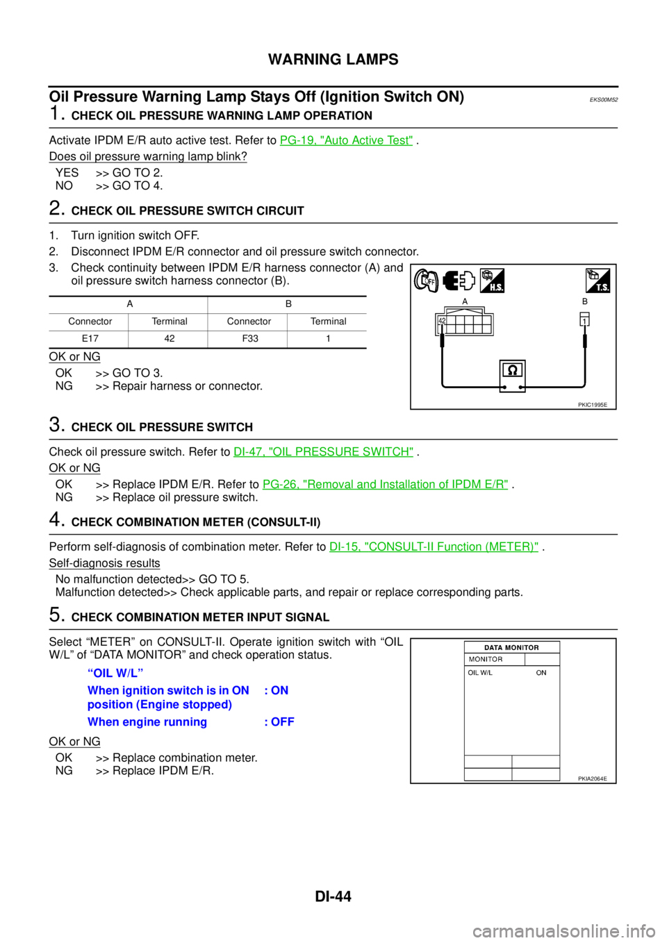
2.CHECK OIL PRESSURE SWITCH CIRCUIT
1. Turn ignition switch OFF.
2. Disconnect IPDM E/R connector and oil pressure switch connector.
3. Check continuity between IPDM E/R harness connector (A) and
oil pressure switch harness connector (B).
OK or NG
OK >> GO TO 3.
NG >> Repair harness or connector.
3.CHECK OIL PRESSURE SWITCH
Check oil pressure switch. Refer toDI-47, "
OIL PRESSURE SWITCH".
OK or NG
OK >> Replace IPDM E/R. Refer toPG-26, "Removal and Installation of IPDM E/R".
NG >> Replace oil pressure switch.
4.CHECK COMBINATION METER (CONSULT-II)
Perform self-diagnosis of combination meter. Refer toDI-15, "
CONSULT-II Function (METER)".
Self-diagnosis results
No malfunction detected>> GO TO 5.
Malfunction detected>> Check applicable parts, and repair or replace corresponding parts.
5.CHECK COMBINATION METER INPUT SIGNAL
Select “METER” on CONSULT-II. Operate ignition switch with “OIL
W/L” of “DATA MONITOR” and check operation status.
OK or NG
OK >> Replace combination meter.
NG >> Replace IPDM E/R.
AB
Connector Terminal Connector Terminal
E17 42 F33 1
PKIC1995E
“OIL W/L”
When ignition switch is in ON
position (Engine stopped):ON
When engine running : OFF
PKIA2064E
Page 955 of 3171
WARNING LAMPS
DI-45
C
D
E
F
G
H
I
J
L
MA
B
DI
Oil Pressure Warning Lamp Does Not Turn Off (Oil Pressure Is Normal)EKS00M53
NOTE:
For oil pressure inspection, refer toLU-5, "
ENGINE OIL PRESSURE CHECK".
1.CHECK OIL PRESSURE WARNING LAMP OPERATION
Activate IPDM E/R auto active test. Refer toPG-19, "
Auto Active Test".
Does oil pressure warning lamp blink?
YES >> GO TO 2.
NO >> GO TO 5.
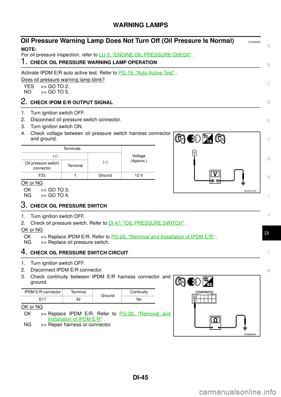
2.CHECK IPDM E/R OUTPUT SIGNAL
1. Turn ignition switch OFF.
2. Disconnect oil pressure switch connector.
3. Turn ignition switch ON.
4. Check voltage between oil pressure switch harness connector
and ground.
OK or NG
OK >> GO TO 3.
NG >> GO TO 4.
3.CHECK OIL PRESSURE SWITCH
1. Turn ignition switch OFF.
2. Check oil pressure switch. Refer toDI-47, "
OIL PRESSURE SWITCH".
OK or NG
OK >> Replace IPDM E/R. Refer toPG-26, "Removal and Installation of IPDM E/R".
NG >> Replace oil pressure switch.
4.CHECK OIL PRESSURE SWITCH CIRCUIT
1. Turn ignition switch OFF.
2. Disconnect IPDM E/R connector.
3. Check continuity between IPDM E/R harness connector and
ground.
OK or NG
OK >> Replace IPDM E/R. Refer toPG-26, "Removal and
Installation of IPDM E/R".
NG >> Repair harness or connector.
Terminals
Vo l ta g e
(Approx.) (+)
(–)
Oil pressure switch
connectorTerminal
F33 1 Ground 12 V
PKIC2151E
IPDM E/R connector Terminal
GroundContinuity
E17 42 No
SKIB6850E
Page 956 of 3171
DI-46
WARNING LAMPS
5.CHECK IPDM E/R (CONSULT-II)
Perform self-diagnosis of IPDM E/R. Refer toPG-16, "
CONSULT-II Function (IPDM E/R)".
Self-diagnosis results
No malfunction detected>>Replace combination meter.
Malfunction detected>> Check applicable parts, and repair or replace corresponding parts.
Oil Pressure Warning Lamp Keeps Blinking (Oil Level Is Normal)EKS00MM6
NOTE:
For engine oil level inspection, refer toLU-5, "
ENGINE OIL LEVEL".
If combination meter detects that oil level sensor is open or short circuit, oil level warning is displayed.
1.CHECK OIL LEVEL SENSOR
1. Turn ignition switch OFF.
2. Disconnect oil level sensor connector.
3. Check oil level sensor. Refer toDI-47, "
OIL LEVEL SENSOR".
OK or NG
OK >> GO TO 2.
NG >> Replace oil level sensor.
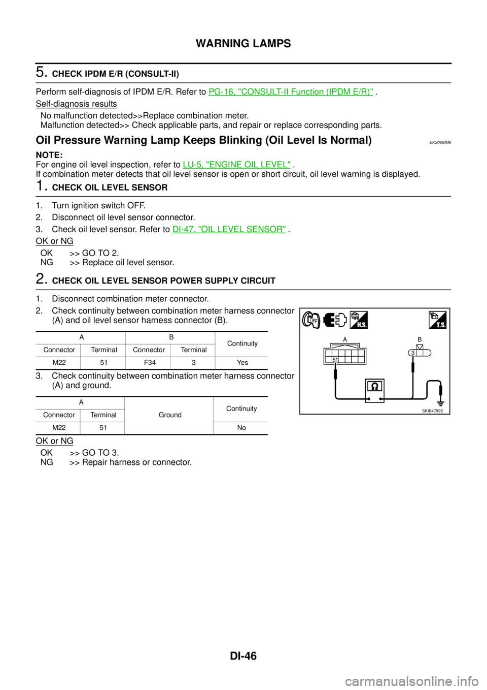
2.CHECK OIL LEVEL SENSOR POWER SUPPLY CIRCUIT
1. Disconnect combination meter connector.
2. Check continuity between combination meter harness connector
(A) and oil level sensor harness connector (B).
3. Check continuity between combination meter harness connector
(A) and ground.
OK or NG
OK >> GO TO 3.
NG >> Repair harness or connector.
AB
Continuity
Connector Terminal Connector Terminal
M22 51 F34 3 Yes
A
GroundContinuity
Connector Terminal
M22 51 No
SKIB4799E
Page 957 of 3171
WARNING LAMPS
DI-47
C
D
E
F
G
H
I
J
L
MA
B
DI
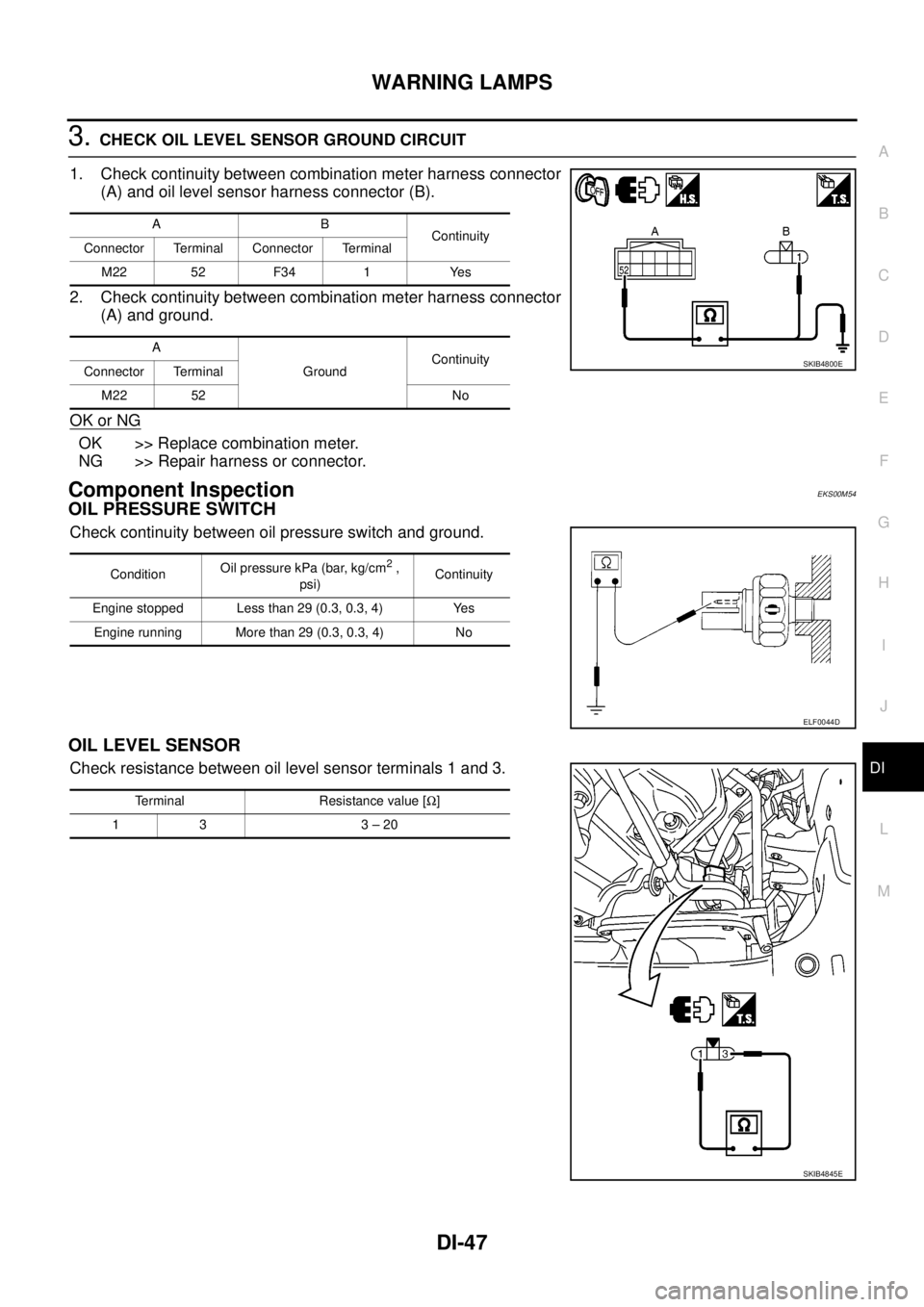
3.CHECK OIL LEVEL SENSOR GROUND CIRCUIT
1. Check continuity between combination meter harness connector
(A) and oil level sensor harness connector (B).
2. Check continuity between combination meter harness connector
(A) and ground.
OK or NG
OK >> Replace combination meter.
NG >> Repair harness or connector.
Component InspectionEKS00M54
OIL PRESSURE SWITCH
Check continuity between oil pressure switch and ground.
OIL LEVEL SENSOR
Check resistance between oil level sensor terminals 1 and 3.
AB
Continuity
Connector Terminal Connector Terminal
M22 52 F34 1 Yes
A
GroundContinuity
Connector Terminal
M22 52 No
SKIB4800E
ConditionOil pressure kPa (bar, kg/cm2,
psi)Continuity
Engine stopped Less than 29 (0.3, 0.3, 4) Yes
Engine running More than 29 (0.3, 0.3, 4) No
ELF0044D
Terminal Resistance value [W]
13 3–20
SKIB4845E
Page 1001 of 3171
ENGINE CONTROL SYSTEM
EC-21
C
D
E
F
G
H
I
J
K
L
MA
EC
If the engine speed is above 2,800 rpm under no load (for example, the shift position is neutral and engine
speed is over 2,800 rpm) fuel will be cut off after some time. The exact time when the fuel is cut off varies
based on engine speed. Fuel cut will be operated until the engine speed reaches 1,500 rpm, then fuel cut will
be cancelled.
NOTE:
This function is different from deceleration control listed underEC-18, "
Fuel Injection Control System"
.
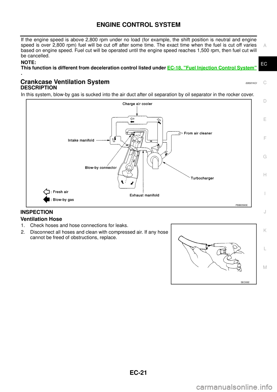
Crankcase Ventilation SystemEBS01KCI
DESCRIPTION
In this system, blow-by gas is sucked into the air duct after oil separation by oil separator in the rocker cover.
INSPECTION
Ventilation Hose
1. Check hoses and hose connections for leaks.
2. Disconnect all hoses and clean with compressed air. If any hose
cannot be freed of obstructions, replace.
PBIB0590E
SEC692