Page 1414 of 3171

EM-32
TURBO CHARGER
Turbocharger Boost Control Actuator
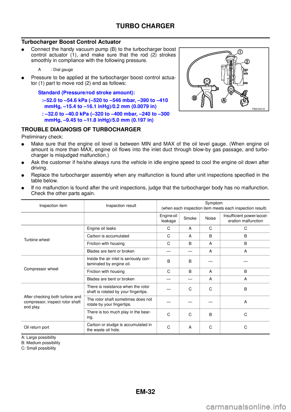
lConnect the handy vacuum pump (B) to the turbocharger boost
control actuator (1), and make sure that the rod (2) strokes
smoothly in compliance with the following pressure.
lPressure to be applied at the turbocharger boost control actua-
tor (1) part to move rod (2) end as follows:
TROUBLE DIAGNOSIS OF TURBOCHARGER
Preliminary check:
lMake sure that the engine oil level is between MIN and MAX of the oil level gauge. (When engine oil
amount is more than MAX, engine oil flows into the inlet duct through blow-by gas passage, and turbo-
charger is misjudged malfunction.)
lAsk the customer if he/she always runs the vehicle in idle engine speed to cool the engine oil down after
driving.
lReplace the turbocharger assembly when any malfunction is found after unit inspections specified in the
table below.
lIf no malfunction is found after the unit inspections, judge that the turbocharger body has no malfunction.
Check the other parts again.
A: Large possibility
B: Medium possibility
C: Small possibilityA : Dial gauge
Standard (Pressure/rod stroke amount):
:–52.0 to –54.6 kPa (–520 to –546 mbar, –390 to –410
mmHg, –15.4 to –16.1 inHg)/0.2 mm (0.0079 in)
: –32.0 to –40.0 kPa (–320 to –400 mbar, –240 to –300
mmHg, –9.45 to –11.8 inHg)/5.0 mm (0.197 in)
PBIC3421E
Inspection item Inspection resultSymptom
(when each inspection item meets each inspection result)
Engine oil
leakageSmoke NoiseInsufficient power/accel-
eration malfunction
Turbine wheelEngine oil leaks C A C C
Carbon is accumulated C A B B
Friction with housing C B A B
Blades are bent or broken — — A A
Compressor wheelInside the air inlet is seriously con-
taminated by engine oil.BB— —
Friction with housing C B A B
Blades are bent or broken — — A A
After checking both turbine and
compressor, inspect rotor shaft
end play.There is resistance when the rotor
shaft is rotated by your fingertips.—CC B
The rotor shaft sometimes does not
rotate by your fingertips.——— A
There is too much play in the bear-
ing.CCB C
Oil return portCarbon or sludge is accumulated in
the waste oil hole.CAC C
Page 1417 of 3171

EXHAUST MANIFOLD
EM-35
C
D
E
F
G
H
I
J
K
L
MA
EM
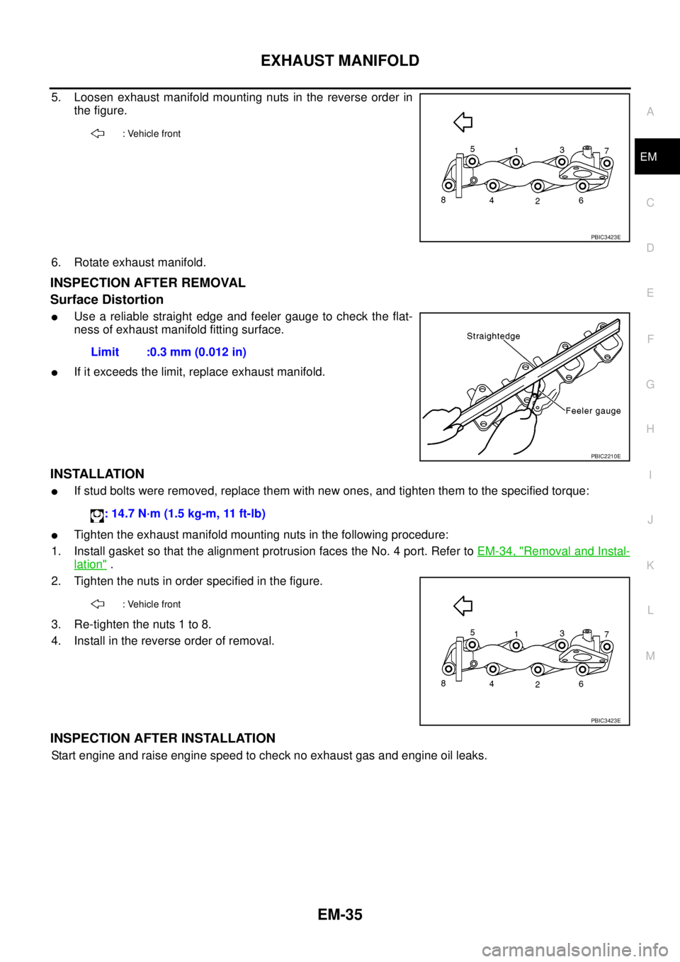
5. Loosen exhaust manifold mounting nuts in the reverse order in
the figure.
6. Rotate exhaust manifold.
INSPECTION AFTER REMOVAL
Surface Distortion
lUse a reliable straight edge and feeler gauge to check the flat-
ness of exhaust manifold fitting surface.
lIf it exceeds the limit, replace exhaust manifold.
INSTALLATION
lIf stud bolts were removed, replace them with new ones, and tighten them to the specified torque:
lTighten the exhaust manifold mounting nuts in the following procedure:
1. Install gasket so that the alignment protrusion faces the No. 4 port. Refer toEM-34, "
Removal and Instal-
lation".
2. Tighten the nuts in order specified in the figure.
3. Re-tighten the nuts 1 to 8.
4. Install in the reverse order of removal.
INSPECTION AFTER INSTALLATION
Start engine and raise engine speed to check no exhaust gas and engine oil leaks.
: Vehicle front
PBIC3423E
Limit :0.3 mm (0.012 in)
PBIC2210E
: 14.7 N·m (1.5 kg-m, 11 ft-lb)
: Vehicle front
PBIC3423E
Page 1422 of 3171
EM-40
OIL PAN AND OIL STRAINER
• Tighten bolts in numerical order to the specified torque.
NOTE:
Pour engine oil or start engine at least 30 minutes after oil pan is
installed.
INSPECTION AFTER INSTALLATION
1. Check engine oil level and add engine oil. Refer toLU-5, "ENGINE OIL".
2. Check for leakage of engine oil when engine is warmed.
3. Stop engine and wait for 10 minutes.
4. Check engine oil level again. Refer toLU-5, "
ENGINE OIL".
: Vehicle front
PBIC3425E
Page 1424 of 3171

EM-42
VACUUM PUMP
VACUUM PUMP
PFP:41920
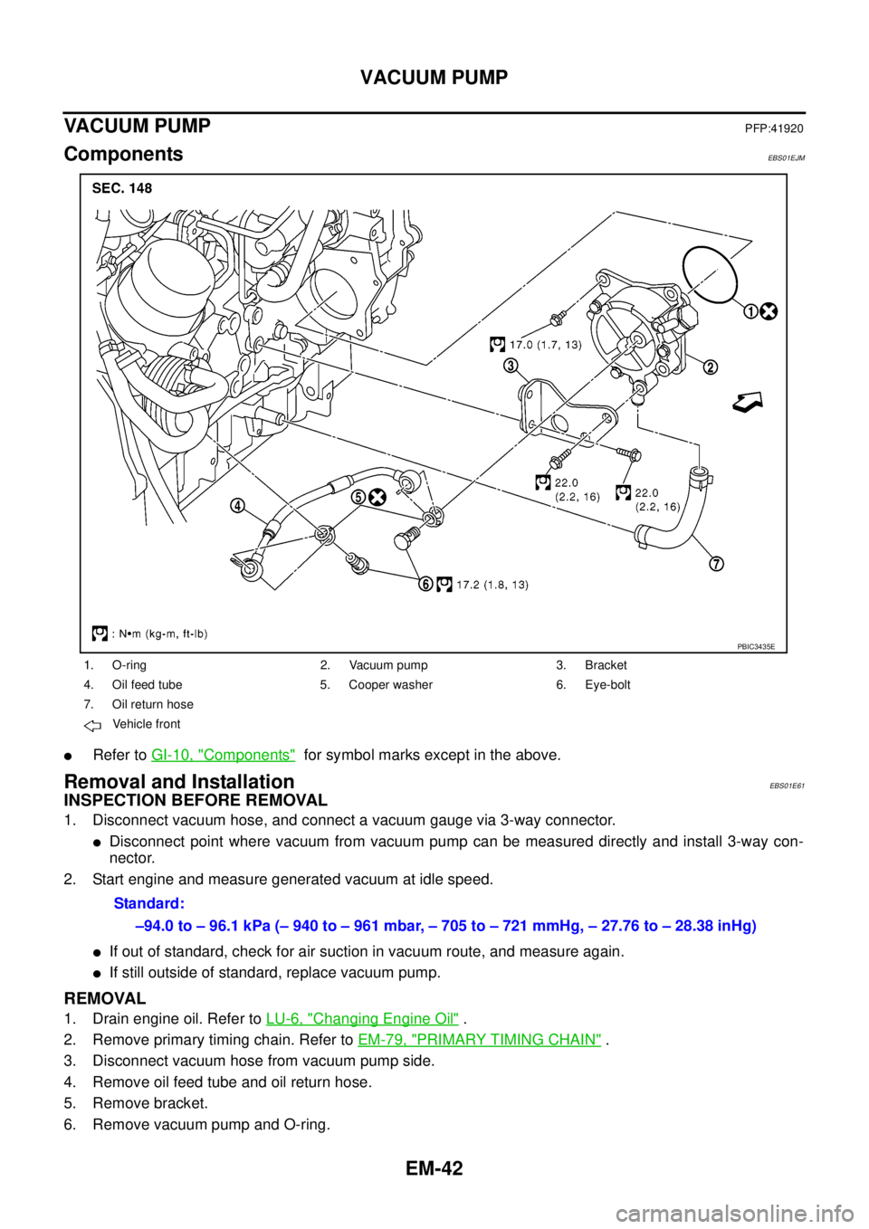
ComponentsEBS01EJM
lRefer toGI-10, "Components"for symbol marks except in the above.
Removal and InstallationEBS01E61
INSPECTION BEFORE REMOVAL
1. Disconnect vacuum hose, and connect a vacuum gauge via 3-way connector.
lDisconnect point where vacuum from vacuum pump can be measured directly and install 3-way con-
nector.
2. Start engine and measure generated vacuum at idle speed.
lIf out of standard, check for air suction in vacuum route, and measure again.
lIf still outside of standard, replace vacuum pump.
REMOVAL
1. Drain engine oil. Refer toLU-6, "Changing Engine Oil".
2. Remove primary timing chain. Refer toEM-79, "
PRIMARY TIMING CHAIN".
3. Disconnect vacuum hose from vacuum pump side.
4. Remove oil feed tube and oil return hose.
5. Remove bracket.
6. Remove vacuum pump and O-ring.
1. O-ring 2. Vacuum pump 3. Bracket
4. Oil feed tube 5. Cooper washer 6. Eye-bolt
7. Oil return hose
Vehicle front
PBIC3435E
Standard:
–94.0 to – 96.1 kPa (– 940 to – 961 mbar, – 705 to – 721 mmHg, – 27.76 to – 28.38 inHg)
Page 1429 of 3171
INJECTION TUBE AND FUEL INJECTOR
EM-47
C
D
E
F
G
H
I
J
K
L
MA
EM
4. Perform air tightness test for spill tube.
lConnect a handy vacuum pump to spill connector. Make sure
that vacuum is retained while applying following vacuum.
lIf outside of standard, reconnect spill tube. (Replace gasket in
this case.)
5. Install rocker cover. Refer toEM-56, "
Removal and Installation".
6. Install nozzle oil seal.
lInsert it straight until its flange fully contacts rocker cover.
CAUTION:
lCheck gutter spring in nozzle oil seal on fuel injector for missing.
7. Connect injection tubes individually to each cylinder in order of
3-4-1-2.
8. Install fuel hoses, spill hose and fuel gallery as shown in the figure.Standard:
–53.3to–66.7kPa(–533to–667mbar,–400to
– 500 mmHg, – 15.75 to – 19.69 inHg)
JEF250Z
SBIA0203E
1. Rocker cover 2. Fuel filter (standard models) 3. Fuel pump
4. Fuel rail 5. Fuel filter (models for cold area)
PBIC3437E
Page 1434 of 3171
EM-52
FUEL PUMP
13. Loosen sprocket nut with the TORX wrench [SST].
14. Remove coupling with a suitable puller.
15. Remove spacer from fuel pump.
16. Remove oil seal from spacer.
INSPECTION AFTER REMOVAL
Timing Chain
Check for cracks and excessive wear at roller links. Replace
timing chain if necessary.
INSTALLATION
1. Install new oil seal to spacer.
2. Install spacer to fuel pump.
MBIA0013E
MBIA0014E
SEM984C
MBIA0045E
Page 1440 of 3171
EM-58
ROCKER COVER
INSPECTION AFTER INSTALLATION
Start engine and increase engine speed to check for fuel leak and engine oil leak.
CAUTION:
Do not touch the engine immediately after stopped as engine becomes extremely hot.
Page 1447 of 3171

CAMSHAFT
EM-65
C
D
E
F
G
H
I
J
K
L
MA
EM
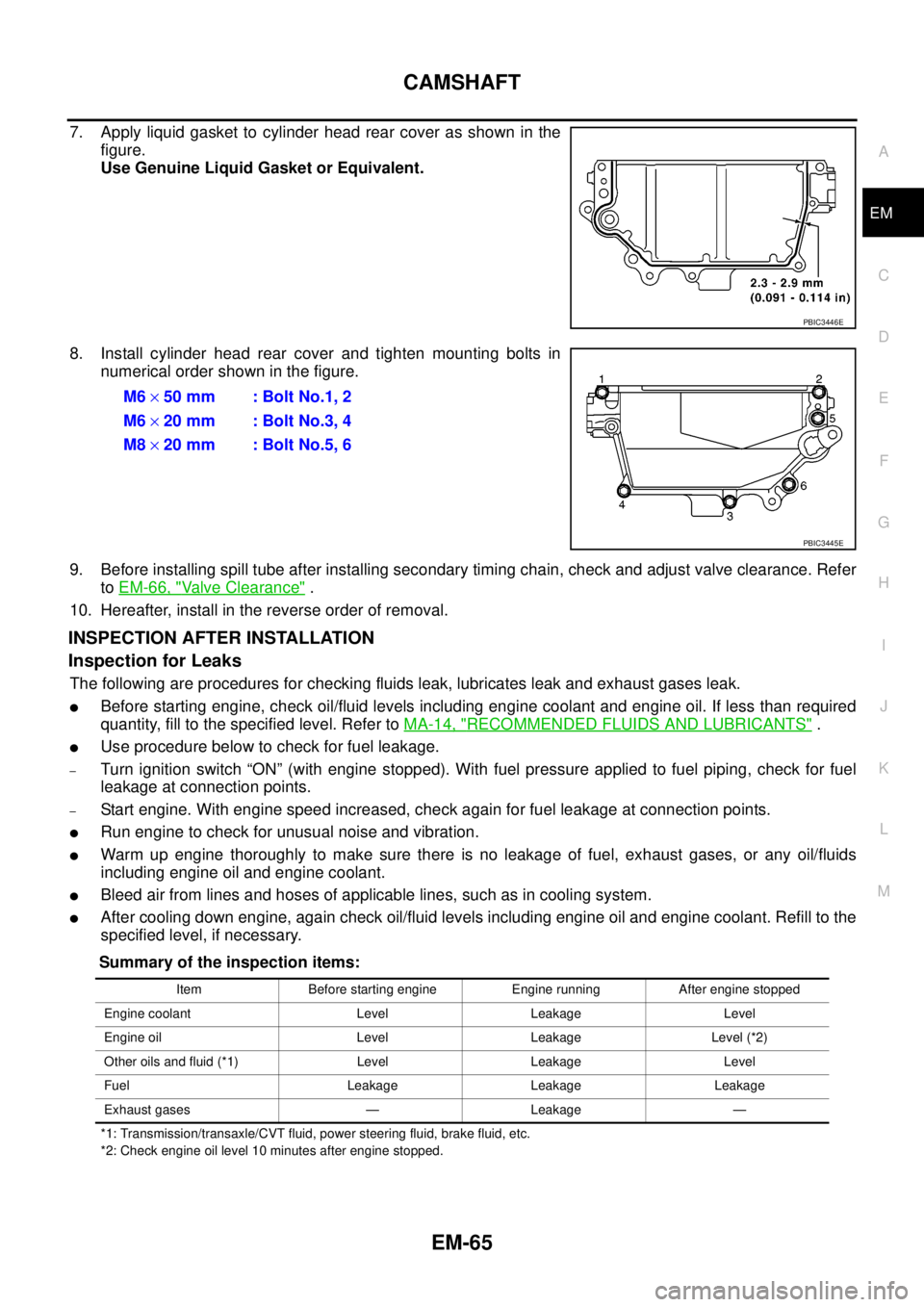
7. Apply liquid gasket to cylinder head rear cover as shown in the
figure.
Use Genuine Liquid Gasket or Equivalent.
8. Install cylinder head rear cover and tighten mounting bolts in
numerical order shown in the figure.
9. Before installing spill tube after installing secondary timing chain, check and adjust valve clearance. Refer
toEM-66, "
Valve Clearance".
10. Hereafter, install in the reverse order of removal.
INSPECTION AFTER INSTALLATION
Inspection for Leaks
The following are procedures for checking fluids leak, lubricates leak and exhaust gases leak.
lBefore starting engine, check oil/fluid levels including engine coolant and engine oil. If less than required
quantity, fill to the specified level. Refer toMA-14, "
RECOMMENDED FLUIDS AND LUBRICANTS".
lUse procedure below to check for fuel leakage.
–Turn ignition switch “ON” (with engine stopped). With fuel pressure applied to fuel piping, check for fuel
leakage at connection points.
–Start engine. With engine speed increased, check again for fuel leakage at connection points.
lRun engine to check for unusual noise and vibration.
lWarm up engine thoroughly to make sure there is no leakage of fuel, exhaust gases, or any oil/fluids
including engine oil and engine coolant.
lBleed air from lines and hoses of applicable lines, such as in cooling system.
lAfter cooling down engine, again check oil/fluid levels including engine oil and engine coolant. Refill to the
specified level, if necessary.
Summary of the inspection items:
*1: Transmission/transaxle/CVT fluid, power steering fluid, brake fluid, etc.
*2: Check engine oil level 10 minutes after engine stopped.
PBIC3446E
M6´50 mm : Bolt No.1, 2
M6´20 mm : Bolt No.3, 4
M8´20 mm : Bolt No.5, 6
PBIC3445E
Item Before starting engine Engine running After engine stopped
Engine coolant Level Leakage Level
Engine oil Level Leakage Level (*2)
Other oils and fluid (*1) Level Leakage Level
Fuel Leakage Leakage Leakage
Exhaust gases — Leakage —