Page 1452 of 3171
EM-70
OIL SEAL
OIL SEAL
PFP:12279
Removal and Installation of Valve Oil SealEBS01EK7
REMOVAL
1. Turn crankshaft until the cylinder requiring new valve oil seals is at TDC. This will prevent valve from drop-
ping into cylinder.
2. Remove camshafts. Refer toEM-59, "
CAMSHAFT".
3. Remove adjusting shims and valve lifters. Refer toEM-59, "
CAMSHAFT".
lCheck the installation positions, and keep them to avoid being confused.
4. Rotate crankshaft, and set piston whose valve oil seal is to be removed to TDC. This will prevent valve
from dropping into cylinder.
5. Remove valve collet.
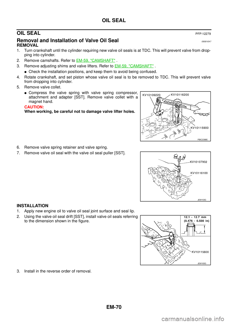
lCompress the valve spring with valve spring compressor,
attachment and adapter [SST]. Remove valve collet with a
magnet hand.
CAUTION:
When working, be careful not to damage valve lifter holes.
6. Remove valve spring retainer and valve spring.
7. Remove valve oil seal with the valve oil seal puller [SST].
INSTALLATION
1. Apply new engine oil to valve oil seal joint surface and seal lip.
2. Using the valve oil seal drift [SST], install valve oil seals referring
to the dimension shown in the figure.
3. Install in the reverse order of removal.
PBIC2388E
JEM153G
JEM165G
Page 1459 of 3171
SECONDARY TIMING CHAIN
EM-77
C
D
E
F
G
H
I
J
K
L
MA
EM
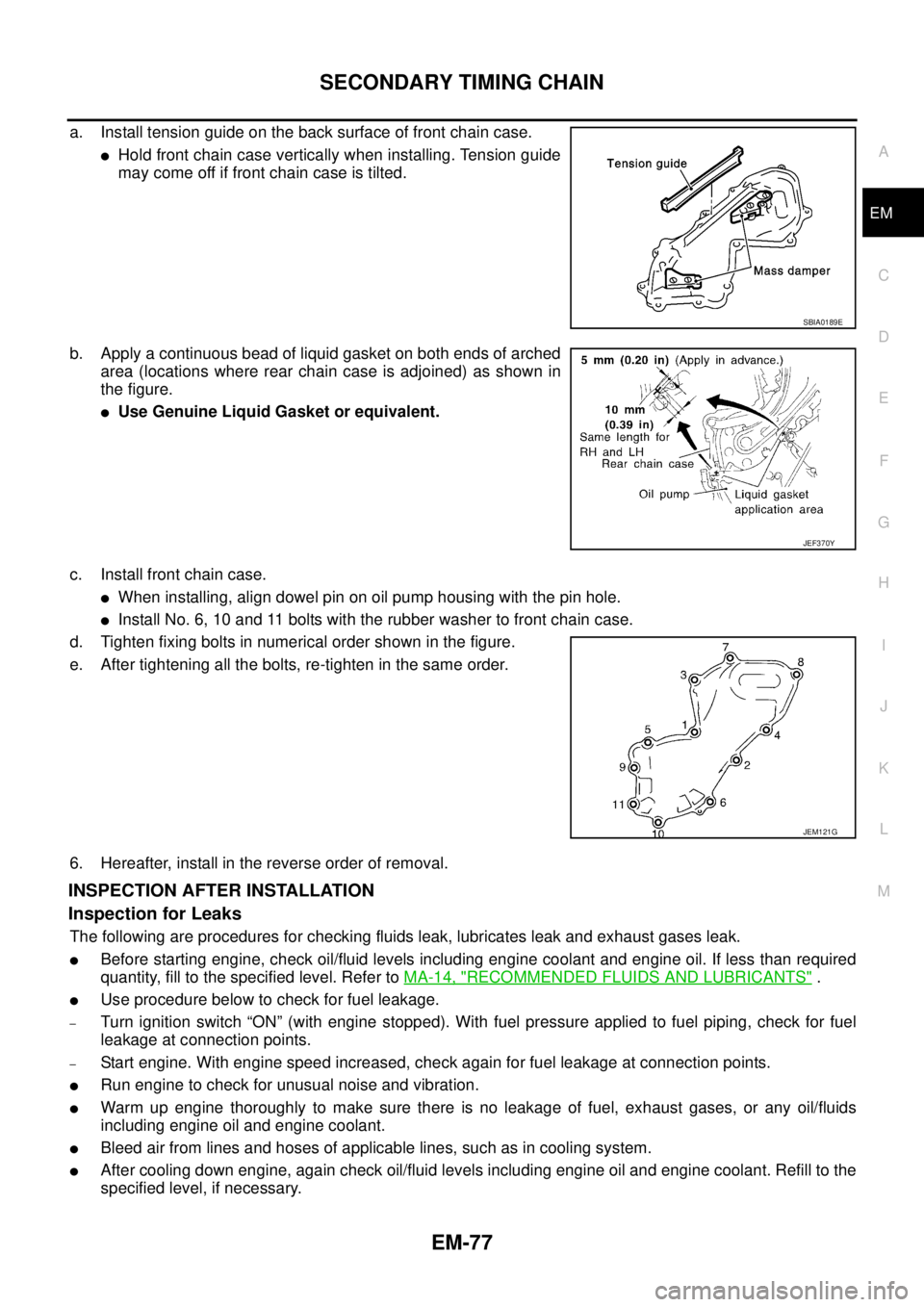
a. Install tension guide on the back surface of front chain case.
lHold front chain case vertically when installing. Tension guide
may come off if front chain case is tilted.
b. Apply a continuous bead of liquid gasket on both ends of arched
area (locations where rear chain case is adjoined) as shown in
the figure.
lUse Genuine Liquid Gasket or equivalent.
c. Install front chain case.
lWhen installing, align dowel pin on oil pump housing with the pin hole.
lInstall No. 6, 10 and 11 bolts with the rubber washer to front chain case.
d. Tighten fixing bolts in numerical order shown in the figure.
e. After tightening all the bolts, re-tighten in the same order.
6. Hereafter, install in the reverse order of removal.
INSPECTION AFTER INSTALLATION
Inspection for Leaks
The following are procedures for checking fluids leak, lubricates leak and exhaust gases leak.
lBefore starting engine, check oil/fluid levels including engine coolant and engine oil. If less than required
quantity, fill to the specified level. Refer toMA-14, "
RECOMMENDED FLUIDS AND LUBRICANTS".
lUse procedure below to check for fuel leakage.
–Turn ignition switch “ON” (with engine stopped). With fuel pressure applied to fuel piping, check for fuel
leakage at connection points.
–Start engine. With engine speed increased, check again for fuel leakage at connection points.
lRun engine to check for unusual noise and vibration.
lWarm up engine thoroughly to make sure there is no leakage of fuel, exhaust gases, or any oil/fluids
including engine oil and engine coolant.
lBleed air from lines and hoses of applicable lines, such as in cooling system.
lAfter cooling down engine, again check oil/fluid levels including engine oil and engine coolant. Refill to the
specified level, if necessary.
SBIA0189E
JEF370Y
JEM121G
Page 1460 of 3171
EM-78
SECONDARY TIMING CHAIN
Summary of the inspection items:
*1: Transmission/transaxle/CVT fluid, power steering fluid, brake fluid, etc.
*2: Check engine oil level 10 minutes after engine stopped.Item Before starting engine Engine running After engine stopped
Engine coolant Level Leakage Level
Engine oil Level Leakage Level (*2)
Other oils and fluid (*1) Level Leakage Level
Fuel Leakage Leakage Leakage
Exhaust gases — Leakage —
Page 1467 of 3171
PRIMARY TIMING CHAIN
EM-85
C
D
E
F
G
H
I
J
K
L
MA
EM
Balancer Unit Mounting Bolt Outer Diameter (4WD Models)
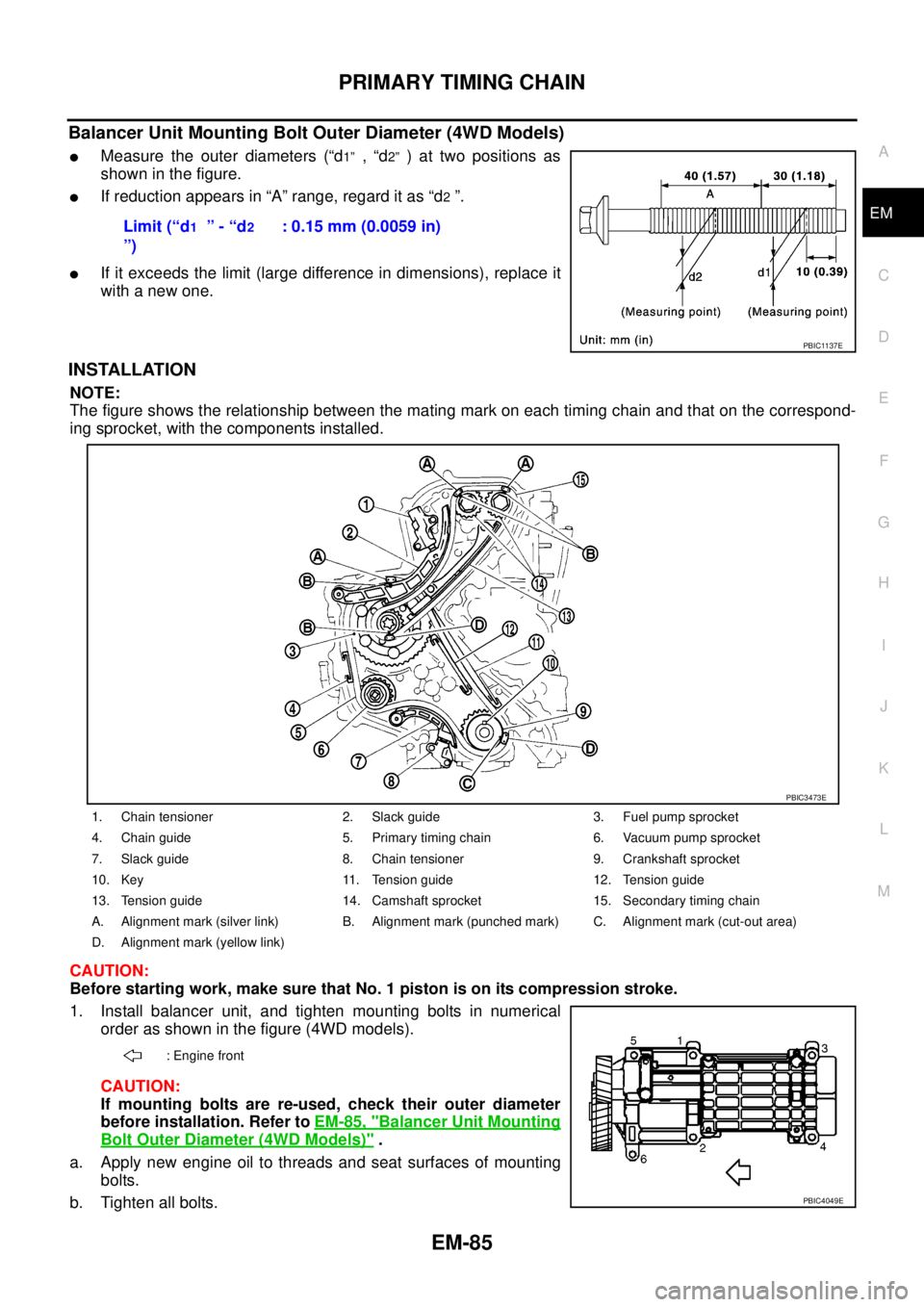
lMeasure the outer diameters (“d1”,“d2”)attwopositionsas
showninthefigure.
lIf reduction appears in “A” range, regard it as “d2”.
lIf it exceeds the limit (large difference in dimensions), replace it
with a new one.
INSTALLATION
NOTE:
The figure shows the relationship between the mating mark on each timing chain and that on the correspond-
ing sprocket, with the components installed.
CAUTION:
Before starting work, make sure that No. 1 piston is on its compression stroke.
1. Install balancer unit, and tighten mounting bolts in numerical
order as shown in the figure (4WD models).
CAUTION:
If mounting bolts are re-used, check their outer diameter
before installation. Refer toEM-85, "
Balancer Unit Mounting
Bolt Outer Diameter (4WD Models)".
a. Apply new engine oil to threads and seat surfaces of mounting
bolts.
b. Tighten all bolts.Limit (“d
1”-“d2
”): 0.15 mm (0.0059 in)
PBIC1137E
1. Chain tensioner 2. Slack guide 3. Fuel pump sprocket
4. Chain guide 5. Primary timing chain 6. Vacuum pump sprocket
7. Slack guide 8. Chain tensioner 9. Crankshaft sprocket
10. Key 11. Tension guide 12. Tension guide
13. Tension guide 14. Camshaft sprocket 15. Secondary timing chain
A. Alignment mark (silver link) B. Alignment mark (punched mark) C. Alignment mark (cut-out area)
D. Alignment mark (yellow link)
: Engine front
PBIC3473E
PBIC4049E
Page 1468 of 3171
EM-86
PRIMARY TIMING CHAIN
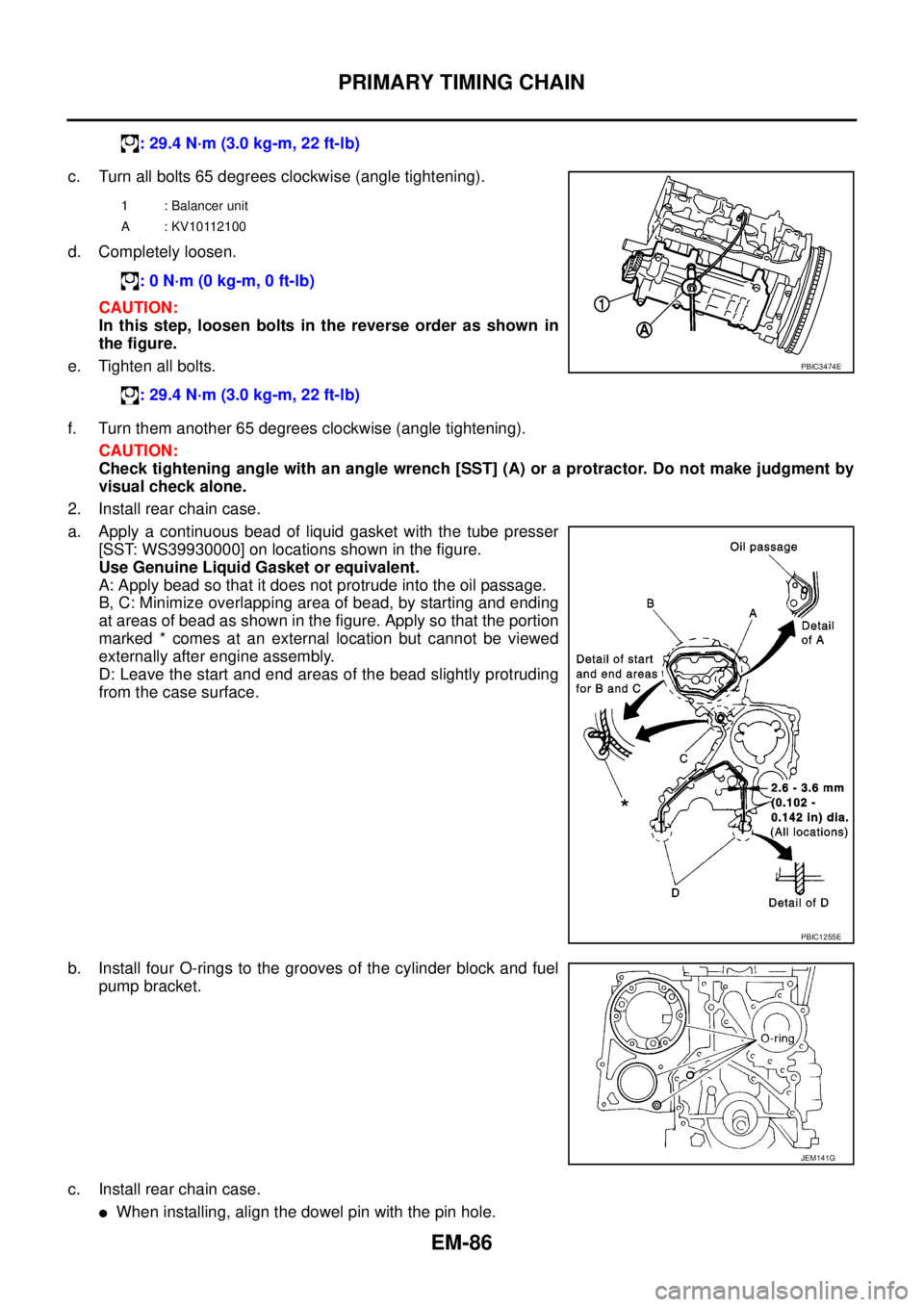
c. Turn all bolts 65 degrees clockwise (angle tightening).
d. Completely loosen.
CAUTION:
In this step, loosen bolts in the reverse order as shown in
the figure.
e. Tighten all bolts.
f. Turn them another 65 degrees clockwise (angle tightening).
CAUTION:
Check tightening angle with an angle wrench [SST] (A) or a protractor. Do not make judgment by
visual check alone.
2. Install rear chain case.
a. Apply a continuous bead of liquid gasket with the tube presser
[SST: WS39930000] on locations shown in the figure.
Use Genuine Liquid Gasket or equivalent.
A: Apply bead so that it does not protrude into the oil passage.
B, C: Minimize overlapping area of bead, by starting and ending
at areas of bead as shown in the figure. Apply so that the portion
marked * comes at an external location but cannot be viewed
externally after engine assembly.
D: Leave the start and end areas of the bead slightly protruding
from the case surface.
b. Install four O-rings to the grooves of the cylinder block and fuel
pump bracket.
c. Install rear chain case.
lWhen installing, align the dowel pin with the pin hole.: 29.4 N·m (3.0 kg-m, 22 ft-lb)
1 : Balancer unit
A : KV10112100
: 0 N·m (0 kg-m, 0 ft-lb)
: 29.4 N·m (3.0 kg-m, 22 ft-lb)
PBIC3474E
PBIC1255E
JEM141G
Page 1472 of 3171
EM-90
PRIMARY TIMING CHAIN
b. Install O-ring into the groove of rear chain case.
c. Install oil pump housing.
lWhen installing, align the inner rotor in the direction of the two facing flats of oil pump drive spacer.
lWhen installing, align the dowel pin with the pin hole.
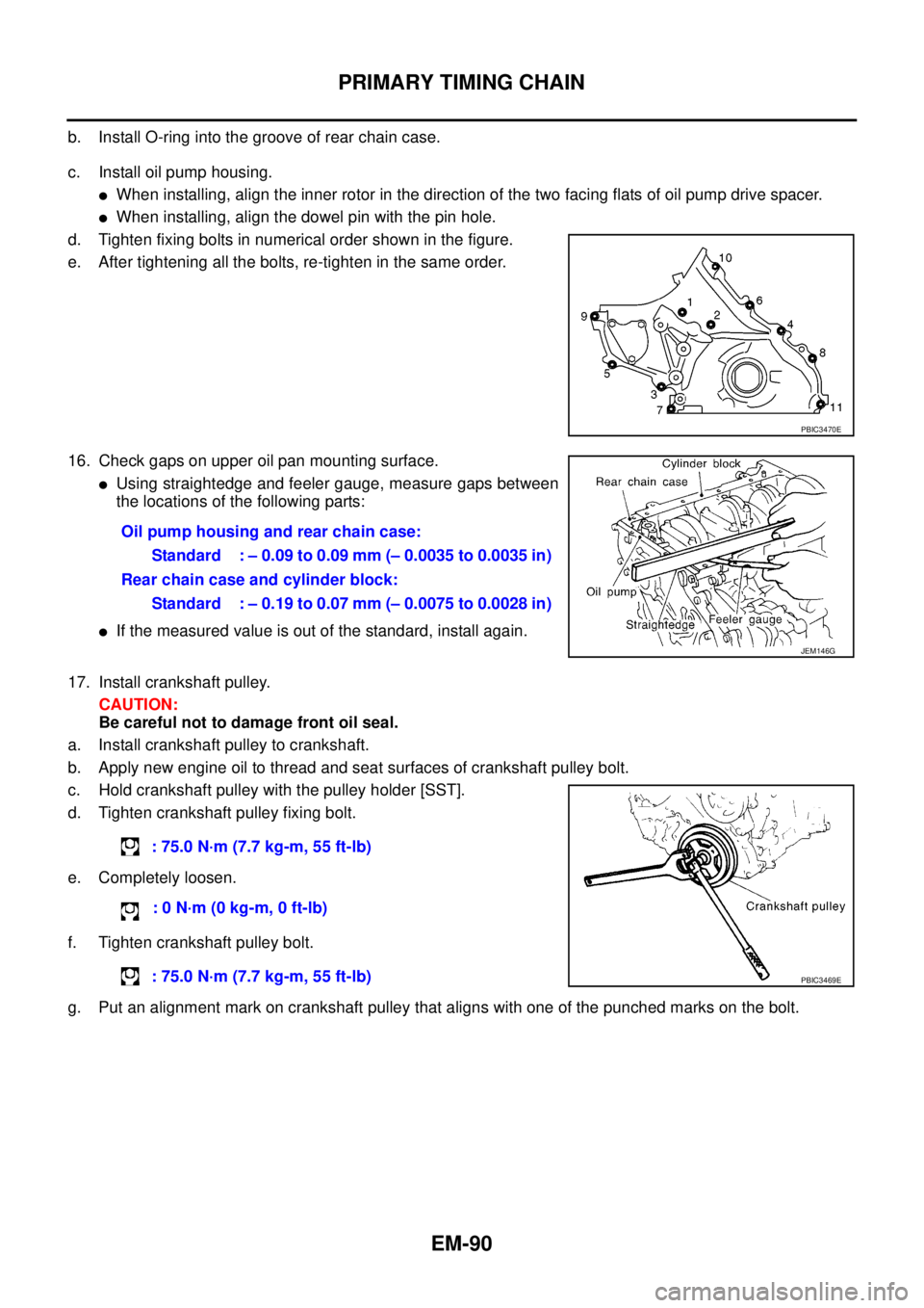
d. Tighten fixing bolts in numerical order shown in the figure.
e. After tightening all the bolts, re-tighten in the same order.
16. Check gaps on upper oil pan mounting surface.
lUsing straightedge and feeler gauge, measure gaps between
the locations of the following parts:
lIf the measured value is out of the standard, install again.
17. Install crankshaft pulley.
CAUTION:
Be careful not to damage front oil seal.
a. Install crankshaft pulley to crankshaft.
b. Apply new engine oil to thread and seat surfaces of crankshaft pulley bolt.
c. Hold crankshaft pulley with the pulley holder [SST].
d. Tighten crankshaft pulley fixing bolt.
e. Completely loosen.
f. Tighten crankshaft pulley bolt.
g. Put an alignment mark on crankshaft pulley that aligns with one of the punched marks on the bolt.
PBIC3470E
Oil pump housing and rear chain case:
Standard : – 0.09 to 0.09 mm (– 0.0035 to 0.0035 in)
Rear chain case and cylinder block:
Standard : – 0.19 to 0.07 mm (– 0.0075 to 0.0028 in)
JEM146G
: 75.0 N·m (7.7 kg-m, 55 ft-lb)
:0N·m(0kg-m,0ft-lb)
: 75.0 N·m (7.7 kg-m, 55 ft-lb)
PBIC3469E
Page 1473 of 3171
PRIMARY TIMING CHAIN
EM-91
C
D
E
F
G
H
I
J
K
L
MA
EM
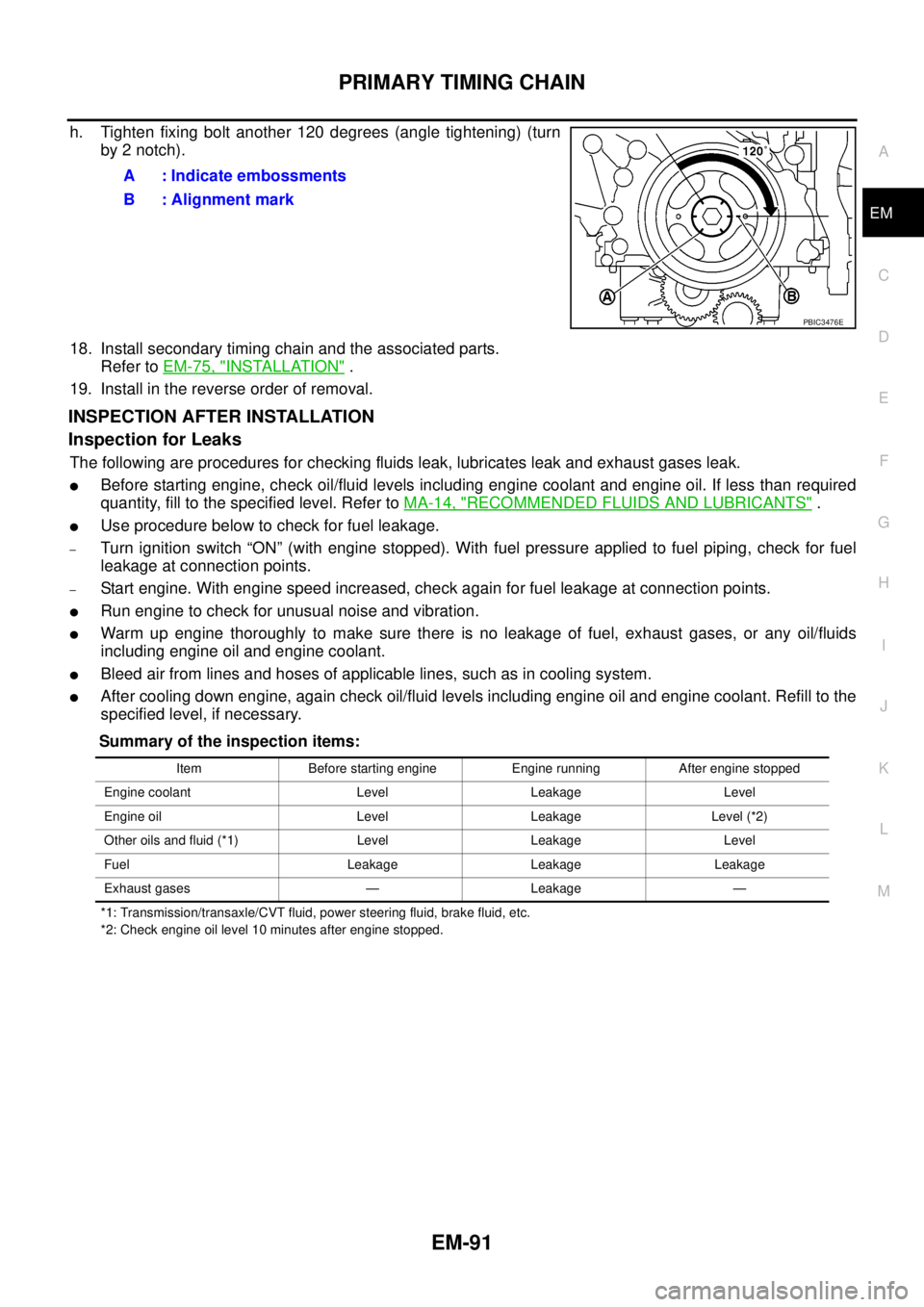
h. Tighten fixing bolt another 120 degrees (angle tightening) (turn
by 2 notch).
18. Install secondary timing chain and the associated parts.
Refer toEM-75, "
INSTALLATION".
19. Install in the reverse order of removal.
INSPECTION AFTER INSTALLATION
Inspection for Leaks
The following are procedures for checking fluids leak, lubricates leak and exhaust gases leak.
lBefore starting engine, check oil/fluid levels including engine coolant and engine oil. If less than required
quantity, fill to the specified level. Refer toMA-14, "
RECOMMENDED FLUIDS AND LUBRICANTS".
lUse procedure below to check for fuel leakage.
–Turn ignition switch “ON” (with engine stopped). With fuel pressure applied to fuel piping, check for fuel
leakage at connection points.
–Start engine. With engine speed increased, check again for fuel leakage at connection points.
lRun engine to check for unusual noise and vibration.
lWarm up engine thoroughly to make sure there is no leakage of fuel, exhaust gases, or any oil/fluids
including engine oil and engine coolant.
lBleed air from lines and hoses of applicable lines, such as in cooling system.
lAfter cooling down engine, again check oil/fluid levels including engine oil and engine coolant. Refill to the
specified level, if necessary.
Summary of the inspection items:
*1: Transmission/transaxle/CVT fluid, power steering fluid, brake fluid, etc.
*2: Check engine oil level 10 minutes after engine stopped.
A : Indicate embossments
B : Alignment mark
PBIC3476E
Item Before starting engine Engine running After engine stopped
Engine coolant Level Leakage Level
Engine oil Level Leakage Level (*2)
Other oils and fluid (*1) Level Leakage Level
Fuel Leakage Leakage Leakage
Exhaust gases — Leakage —
Page 1475 of 3171
CYLINDER HEAD
EM-93
C
D
E
F
G
H
I
J
K
L
MA
EM
Compression pressure
Unit: kPa (bar, kg/cm2, psi)/rpm
lWhen engine rpm is out of the specified range, check the specific gravity of battery liquid. Measure
again under corrected conditions.
lIf engine rpm exceeds the limit, check valve clearance and combustion chamber components (valves,
valve seats, cylinder head gaskets, piston rings, pistons, cylinder bores, cylinder block upper and lower
surfaces) and measure again.
lIf compression pressure is low in some cylinders, apply engine oil from glow plug installation hole. Then
check pressure again.
–If compression pressure becomes normal after applying engine oil, piston ring may be worn or dam-
aged. Check piston ring for malfunction. If any, replace piston ring.
–If compression pressure is still low after applying engine oil, valve may be malfunctioning. Check valve
for malfunction. If contact malfunction is found, replace valve or valve seat.
lIf compression pressure in adjacent two cylinders is low after applying engine oil, pressure may be
leaking from gasket. In this case, replace cylinder head gasket.
9. Complete this operation as follows:
a. Turn the ignition switch to “OFF”.
b. Disconnect the battery cable from the negative terminal.
c. Install glow plug and install all the parts removed in step 4.
d. Install fuse [EGI (20A)].
e. Connect the battery cable to the negative terminal.
f. Using CONSULT-II make sure no DTC is indicated for items of self-diagnosis.
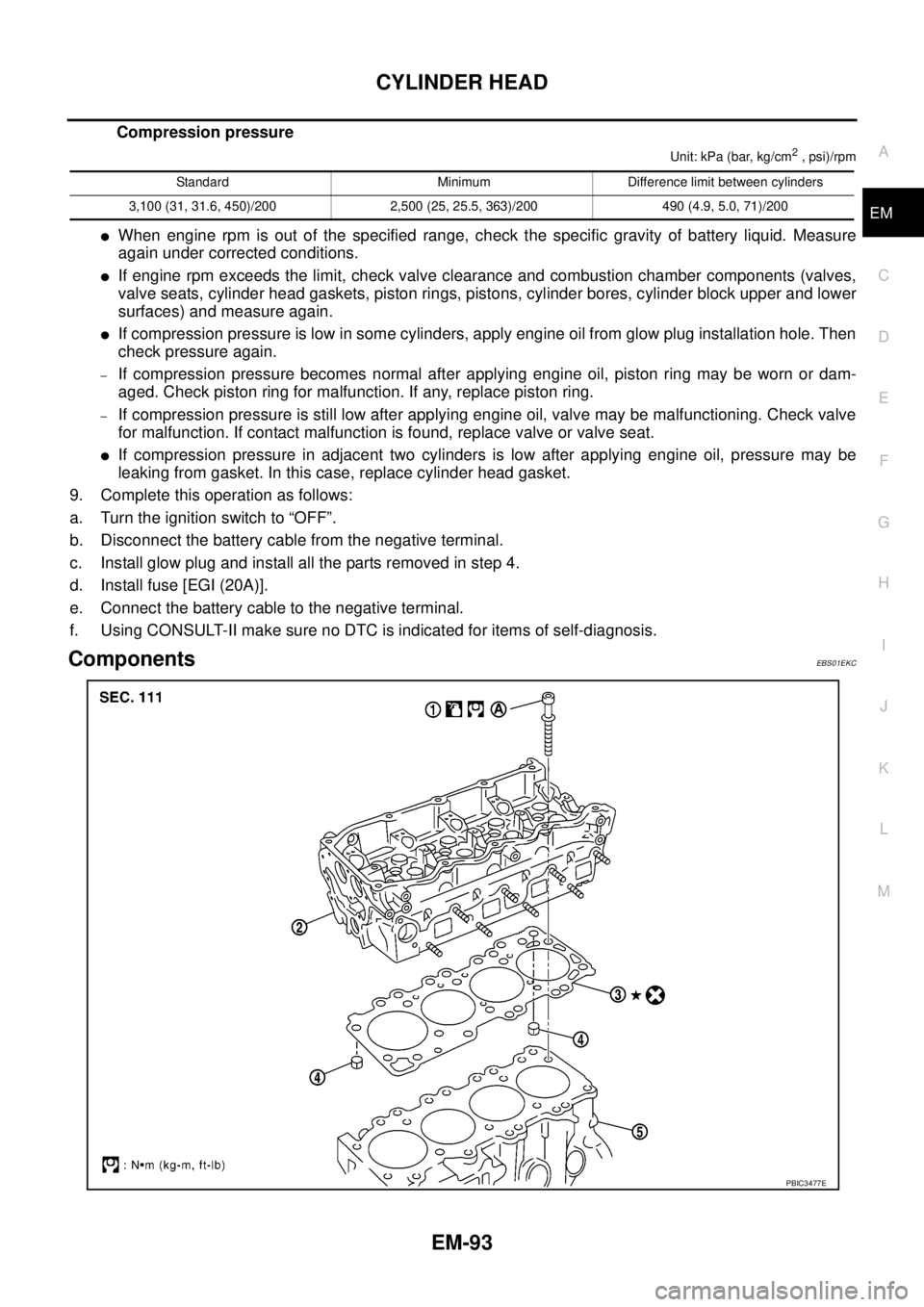
ComponentsEBS01EKC
Standard Minimum Difference limit between cylinders
3,100 (31, 31.6, 450)/200 2,500 (25, 25.5, 363)/200 490 (4.9, 5.0, 71)/200
PBIC3477E