Page 3079 of 3171

TF-112
TRANSFER ASSEMBLY
INSTALLATION
Note the following, and install in the reverse order of removal.
lTighten the bolts to specification.
lAfter the installation, check the transfer fluid level and fluid leak-
age. Refer toTF-12, "
FLUID LEAKAGE AND FLUID LEVEL".
lAfter filling, start the engine for one minute. Then stop the
engine and recheck the transfer fluid.
lAfter the installation, check the 4WD shift indicator pattern. If
NG, adjust the position between the transfer assembly and
transfer control unit. Refer toTF-4, "
Precautions for Transfer
Assembly and Transfer Control Unit Replacement".
Disassembly and AssemblyEDS0032P
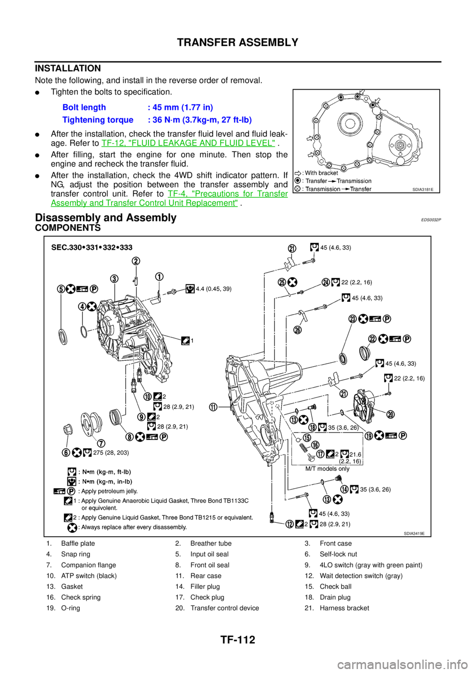
COMPONENTS
Bolt length : 45 mm (1.77 in)
Tightening torque : 36 N·m (3.7kg-m, 27 ft-lb)
SDIA3181E
1. Baffle plate 2. Breather tube 3. Front case
4. Snap ring 5. Input oil seal 6. Self-lock nut
7. Companion flange 8. Front oil seal 9. 4LO switch (gray with green paint)
10. ATP switch (black) 11. Rear case 12. Wait detection switch (gray)
13. Gasket 14. Filler plug 15. Check ball
16. Check spring 17. Check plug 18. Drain plug
19. O-ring 20. Transfer control device 21. Harness bracket
SDIA3419E
Page 3082 of 3171
TRANSFER ASSEMBLY
TF-115
C
E
F
G
H
I
J
K
L
MA
B
TF
7. Remove the front oil seal from the front case, using Tool.
CAUTION:
Do not damage front case or front drive shaft.
8. Remove the 4LO switch [gray (with green paint)] and ATP switch
(black) from the front case.
9. Remove the wait detection switch (gray) from the rear case.
10. Remove check plug, check spring and check ball (M/T models
only).
11. Remove the dust cover from the rear case, using suitable tool.
CAUTION:
Do not damage rear case.Tool number : KV381054S0
SDIA2423E
PDIA0090E
PDIA0091E
LDIA0193E
PDIA0092E
Page 3093 of 3171

TF-126
TRANSFER ASSEMBLY
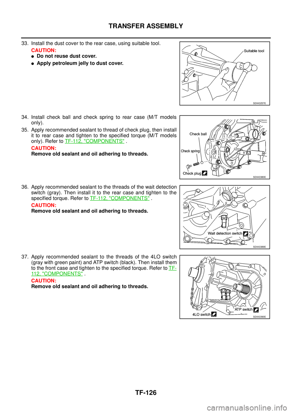
33. Install the dust cover to the rear case, using suitable tool.
CAUTION:
lDo not reuse dust cover.
lApply petroleum jelly to dust cover.
34. Install check ball and check spring to rear case (M/T models
only).
35. Apply recommended sealant to thread of check plug, then install
it to rear case and tighten to the specified torque (M/T models
only). Refer toTF-112, "
COMPONENTS".
CAUTION:
Remove old sealant and oil adhering to threads.
36. Apply recommended sealant to the threads of the wait detection
switch(gray).Theninstallittotherearcaseandtightentothe
specified torque. Refer toTF-112, "
COMPONENTS".
CAUTION:
Remove old sealant and oil adhering to threads.
37. Apply recommended sealant to the threads of the 4LO switch
(gray with green paint) and ATP switch (black). Then install them
to the front case and tighten to the specified torque. Refer toTF-
11 2 , "COMPONENTS".
CAUTION:
Remove old sealant and oil adhering to threads.
SDIA3257E
SDIA3380E
SDIA3389E
SDIA3390E
Page 3097 of 3171

TF-130
PLANETARY CARRIER
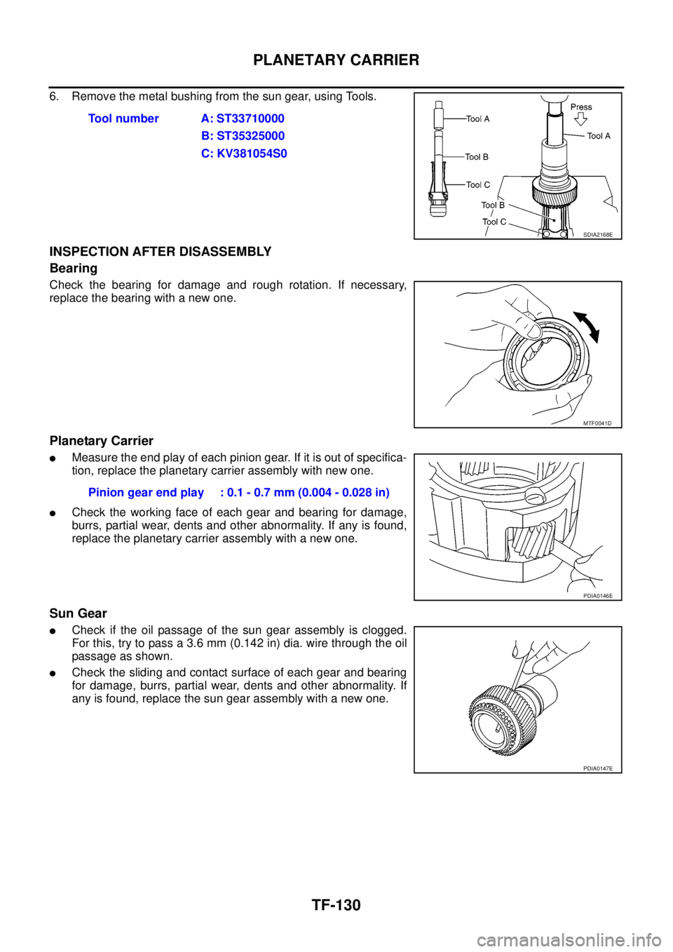
6. Remove the metal bushing from the sun gear, using Tools.
INSPECTION AFTER DISASSEMBLY
Bearing
Check the bearing for damage and rough rotation. If necessary,
replace the bearing with a new one.
Planetary Carrier
lMeasure the end play of each pinion gear. If it is out of specifica-
tion, replace the planetary carrier assembly with new one.
lCheck the working face of each gear and bearing for damage,
burrs, partial wear, dents and other abnormality. If any is found,
replace the planetary carrier assembly with a new one.
Sun Gear
lCheck if the oil passage of the sun gear assembly is clogged.
For this, try to pass a 3.6 mm (0.142 in) dia. wire through the oil
passage as shown.
lCheck the sliding and contact surface of each gear and bearing
for damage, burrs, partial wear, dents and other abnormality. If
any is found, replace the sun gear assembly with a new one.Tool number A: ST33710000
B: ST35325000
C: KV381054S0
SDIA2168E
MTF0041D
Pinion gear end play : 0.1 - 0.7 mm (0.004 - 0.028 in)
PDIA0146E
PDIA0147E