Page 1789 of 3171
LAN-12
[CAN]
TROUBLE DIAGNOSES WORK FLOW
NOTE:
There is a case that some of “CAN DIAG SUPPORT MNTR” and “SELF-DIAG RESULTS” are not needed for
diagnosis. In the case, “UNKWN” and “CAN COMM CIRCUIT(U1000)” in “Check sheet results (example)”
change to “–”. Then, ignore check marks on the check sheet table.
4. Perform system diagnosis for possible causes identified.
5. Perform diagnosis again after inspection and repair. Make sure that repair is completely performed, and
then end the procedure.
Start CAN system trouble diagnosis if this procedure can be confirmed. Refer toLAN-30, "
CAN Communica-
tion Unit".
PKIC2528E
Page 1790 of 3171
TROUBLE DIAGNOSES WORK FLOW
LAN-13
[CAN]
C
D
E
F
G
H
I
J
L
MA
B
LAN
Example of Filling in Check Sheet When Initial Conditions Are Not Reproduced
1. See “SELF-DIAG RESULTS” of all units attached to the check sheet. If “CAN COMM CIRCUIT” or “CAN
COMM CIRCUIT [U1000]” is displayed, put a check mark to the applicable column of self-diagnostic
results of the check sheet table.
NOTE:
lFor “ENGINE”, “CAN COMM CIRCUIT [U1000]” is displayed. Put a check mark to it.
lFor “A/T”, “CAN COMM CIRCUIT [U1000]” is displayed. Put a check mark to it.
lFor “HVAC”, “NO DTC IS DETECTED” is displayed. Do not put a check mark to it.
lFor “BCM”, “NO DTC IS DETECTED” is displayed. Do not put a check mark to it.
lFor “METER”, “CAN COMM CIRCUIT [U1000]” is displayed. Put a check mark to it.
lFor “ABS”, “NO DTC IS DETECTED” is displayed. Do not put a check mark to it.
lFor “IPDM E/R”, “NO DTC IS DETECTED” is displayed. Do not put a check mark to it.
PKIC2529E
Page 1791 of 3171
LAN-14
[CAN]
TROUBLE DIAGNOSES WORK FLOW
NOTE:
There is a case that some of “CAN DIAG SUPPORT MNTR” and “SELF-DIAG RESULTS” are not needed for
diagnosis. In the case, “UNKWN” and “CAN COMM CIRCUIT(U1000)” in “Check sheet results (example)”
change to “–”. Then, ignore check marks on the check sheet table.
2. For the selected possible causes, it is expected that malfunctions have been found in the past.
PKIC2530E
Page 2546 of 3171

IPDM E/R (INTELLIGENT POWER DISTRIBUTION MODULE ENGINE ROOM)
PG-17
C
D
E
F
G
H
I
J
L
MA
B
PG
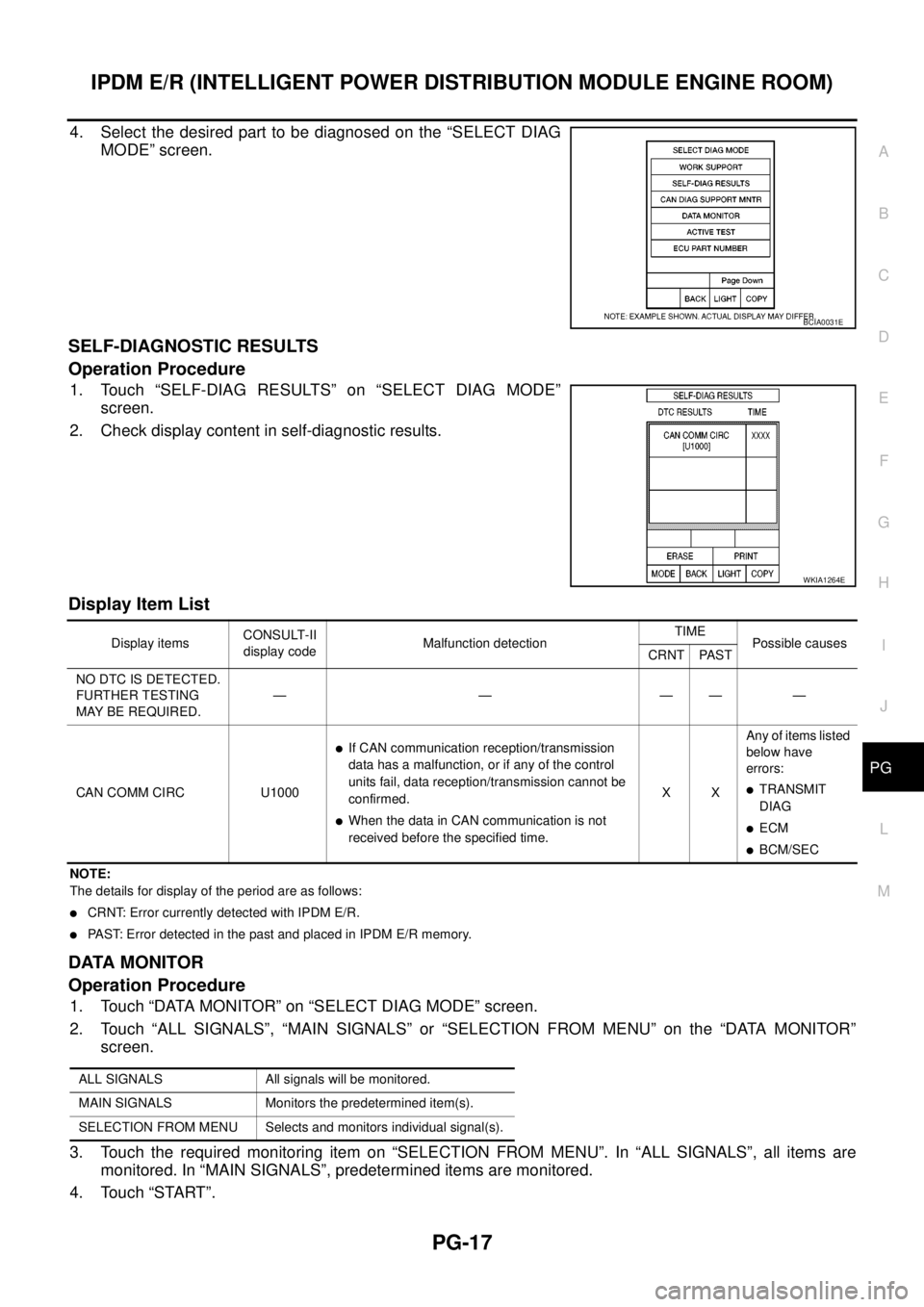
4. Select the desired part to be diagnosed on the “SELECT DIAG
MODE” screen.
SELF-DIAGNOSTIC RESULTS
Operation Procedure
1. Touch “SELF-DIAG RESULTS” on “SELECT DIAG MODE”
screen.
2. Check display content in self-diagnostic results.
Display Item List
NOTE:
The details for display of the period are as follows:
lCRNT: Error currently detected with IPDM E/R.
lPAST: Error detected in the past and placed in IPDM E/R memory.
DATA MONITOR
Operation Procedure
1. Touch “DATA MONITOR” on “SELECT DIAG MODE” screen.
2. Touch “ALL SIGNALS”, “MAIN SIGNALS” or “SELECTION FROM MENU” on the “DATA MONITOR”
screen.
3. Touch the required monitoring item on “SELECTION FROM MENU”. In “ALL SIGNALS”, all items are
monitored. In “MAIN SIGNALS”, predetermined items are monitored.
4. Touch “START”.
BCIA0031E
WKIA1264E
Display itemsCONSULT-II
display codeMalfunction detectionTIME
Possible causes
CRNT PAST
NO DTC IS DETECTED.
FURTHER TESTING
MAYBEREQUIRED.—————
CAN COMM CIRC U1000
lIf CAN communication reception/transmission
data has a malfunction, or if any of the control
units fail, data reception/transmission cannot be
confirmed.
lWhen the data in CAN communication is not
received before the specified time.XXAny of items listed
below have
errors:
lTRANSMIT
DIAG
lECM
lBCM/SEC
ALL SIGNALS All signals will be monitored.
MAIN SIGNALS Monitors the predetermined item(s).
SELECTION FROM MENU Selects and monitors individual signal(s).
Page 2554 of 3171

IPDM E/R (INTELLIGENT POWER DISTRIBUTION MODULE ENGINE ROOM)
PG-25
C
D
E
F
G
H
I
J
L
MA
B
PG
Inspection with CONSULT-II (Self-Diagnosis)EKS00PAG
CAUTION:
If a CONSULT-II is used with no connection of CONSULT-II CONVERTER, malfunctions might be
detected in self-diagnosis depending on which control unit(s) carry out CAN communication.
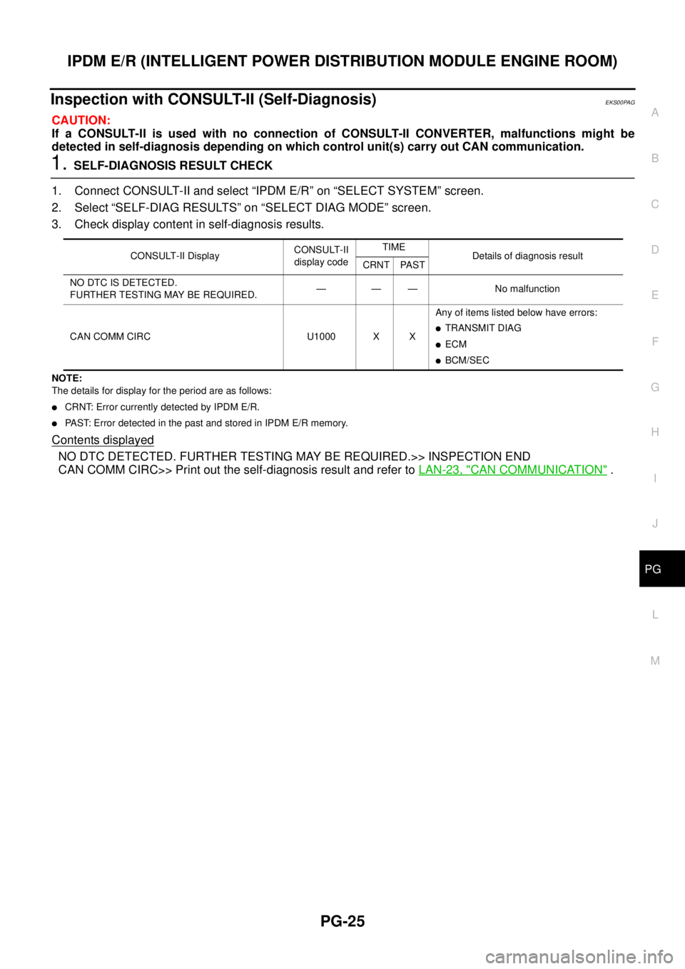
1.SELF-DIAGNOSIS RESULT CHECK
1. Connect CONSULT-II and select “IPDM E/R” on “SELECT SYSTEM” screen.
2. Select “SELF-DIAG RESULTS” on “SELECT DIAG MODE” screen.
3. Check display content in self-diagnosis results.
NOTE:
The details for display for the period are as follows:
lCRNT: Error currently detected by IPDM E/R.
lPAST: Error detected in the past and stored in IPDM E/R memory.
Contents displayed
NO DTC DETECTED. FURTHER TESTING MAY BE REQUIRED.>> INSPECTION END
CAN COMM CIRC>> Print out the self-diagnosis result and refer toLAN-23, "
CAN COMMUNICATION".
CONSULT-II DisplayCONSULT-II
display codeTIME
Details of diagnosis result
CRNT PAST
NO DTC IS DETECTED.
FURTHER TESTING MAY BE REQUIRED.— — — No malfunction
CAN COMM CIRC U1000 X XAny of items listed below have errors:
lTRANSMIT DIAG
lECM
lBCM/SEC
Page 2755 of 3171
![NISSAN NAVARA 2005 Repair Workshop Manual RFD-52
[WITH ELECTRONIC LOCKING DIFFERENTIAL]
TROUBLE DIAGNOSIS
CAUTION:
If “CAN COMM CIRCUIT [U1000]” is displayed with other DTCs, first perform the trouble diagnosis for CAN communication
line. NISSAN NAVARA 2005 Repair Workshop Manual RFD-52
[WITH ELECTRONIC LOCKING DIFFERENTIAL]
TROUBLE DIAGNOSIS
CAUTION:
If “CAN COMM CIRCUIT [U1000]” is displayed with other DTCs, first perform the trouble diagnosis for CAN communication
line.](/manual-img/5/57362/w960_57362-2754.png)
RFD-52
[WITH ELECTRONIC LOCKING DIFFERENTIAL]
TROUBLE DIAGNOSIS
CAUTION:
If “CAN COMM CIRCUIT [U1000]” is displayed with other DTCs, first perform the trouble diagnosis for CAN communication
line.
How to Erase Self-diagnostic Results
1. Perform applicable inspection of malfunctioning item and then repair or replace.
2. Start engine and select “SELF-DIAG RESULTS” mode for “DIFF LOCK” with CONSULT-II.
3. Touch “ERASE” on CONSULT-II screen to erase DTC memory.
CAUTION:
If memory cannot be erased, perform diagnosis.
POSI SW ON
[P1839]When differential lock position switch is ON, rotation difference
occurs in wheel speed (rear wheel right and left).RFD-60, "Differential Lock Posi-
tion Switch"
RELAY
[P1844]Differential lock control unit detects as irregular by comparing target
value with monitor value.RFD-63, "Differential Lock Sole-
noid Relay",RFD-64, "Differen-
tial Lock Solenoid"
SOL CIRCUIT
[P1847]Malfunction is detected in differential lock control unit internal circuit.RFD-64, "Differential Lock Sole-
noid"
SOL DISCONNECT
[P1848]lDifferential lock solenoid internal circuit or harness is open.
lDifferential lock solenoid relay does not switch to ON position.RFD-64, "
Differential Lock Sole-
noid"
SOL SHORT
[P1849]Differential lock solenoid internal circuit or harness is shorted.RFD-64, "Differential Lock Sole-
noid"
SOL CURRENT
[P1850]Differential lock solenoid relay does not switch to OFF position.RFD-64, "Differential Lock Sole-
noid"
ABS SYSTEM
[C1203]Malfunction related to wheel sensor has been detected by ABS
actuator and electric unit (control unit).RFD-68, "ABS System"
CAN COMM CIRCUIT
[U1000]Malfunction has been detected from CAN communication line.RFD-69, "CAN Communication
Line"
NO DTC IS DETECTED.
FURTHER TESTING MAY
BE REQUIRED.No NG item has been detected. — Items (CONSULT-II screen
terms)Diagnostic item is detected when... Check item
Page 2772 of 3171
TROUBLE DIAGNOSIS FOR SYSTEM
RFD-69
[WITH ELECTRONIC LOCKING DIFFERENTIAL]
C
E
F
G
H
I
J
K
L
MA
B
RFD
CAN Communication LineEDS003B8
DIAGNOSTIC PROCEDURE
1.CHECK CAN COMMUNICATION CIRCUIT
With CONSULT-II
1. Turn ignition switch “ON” and start engine.
2. Select “SELF-DIAG RESULTS” mode for “DIFF LOCK” with in CONSULT-II.
3. Perform the self-diagnosis.
Is the
“CAN COMM CIRCUIT [U1000]”displayed?
YES >> Go toLAN-3, "Precautions When Using CONSULT-II".
NO >>INSPECTION END
SDIA1850E
Page 3013 of 3171
![NISSAN NAVARA 2005 Repair Workshop Manual TF-46
TROUBLE DIAGNOSIS
CAUTION:
If “CAN COMM CIRCUIT [U1000]” is displayed with other DTCs, first perform the trouble diagnosis for CAN communication
line.
NOTE:
If “SHIFT ACT POSI SW [P1818]� NISSAN NAVARA 2005 Repair Workshop Manual TF-46
TROUBLE DIAGNOSIS
CAUTION:
If “CAN COMM CIRCUIT [U1000]” is displayed with other DTCs, first perform the trouble diagnosis for CAN communication
line.
NOTE:
If “SHIFT ACT POSI SW [P1818]�](/manual-img/5/57362/w960_57362-3012.png)
TF-46
TROUBLE DIAGNOSIS
CAUTION:
If “CAN COMM CIRCUIT [U1000]” is displayed with other DTCs, first perform the trouble diagnosis for CAN communication
line.
NOTE:
If “SHIFT ACT POSI SW [P1818]” or “SHIFT ACT CIR [P1819]” is displayed, first erase self-diagnostic results. (“SHIFT ACT POSI SW
[P1818]” or “SHIFT ACT CIR [P1819]” may be displayed after installing transfer control unit or transfer assembly.)
How to Erase Self-diagnostic Results
1. Perform applicable inspection of malfunctioning item and then repair or replace.
2. Start engine and select “SELF-DIAG RESULTS” mode for “ALL MODE AWD/4WD” with CONSULT-II.
3. Touch “ERASE” on CONSULT-II screen to erase DTC memory.
CAUTION:
If memory cannot be erased, perform applicable diagnosis.
CONTROL UNIT 4
[P1809]AD converter system of transfer control unit is malfunctioning.TF-54, "Transfer Control Unit"
4L POSI SW TF
[P1810]Improper signal from 4LO switch is input due to open or short circuit.TF-56, "4LO Switch"
BATTERY VOLTAGE
[P1811]Power supply voltage for transfer control unit is abnormally low
while driving.TF-52, "Power Supply Circuit For
Transfer Control Unit"
4WD MODE SW
[P1813]More than two switch inputs are simultaneously detected due to
short circuit of 4WD shift switch.TF-59, "4WD Shift Switch"
4WD DETECT SWITCH
[P1814]Improper signal from wait detection switch is input due to open or
short circuit.TF-63, "Wait Detection Switch"
PNP SW/CIRC
[P1816]When A/T PNP switch signal is malfunction or communication error
between the vehicles.TF-66, "PNP Switch Signal
(TCM)"
SHIFT ACTUATOR
[P1817]
lMotor does not operate properly due to open or short circuit in
actuator motor.
lMalfunction is detected in the actuator motor. (When 4WD shift
switch is operated and actuator motor is not operated)
lMalfunction is detected in transfer shift high relay and transfer
shift low relay.TF-67, "
Actuator Motor"
SHIFT ACT POSI SW
[P1818]lImproper signal from actuator position switch is input due to open
or short circuit.
lMalfunction is detected in actuator position switch.TF-75, "
Actuator Position
Switch"
SHIFT ACT CIR
[P1819]lMalfunction is detected in transfer shut off relay 1 and transfer
shut off relay 2.
lMalfunction occurs in transfer control device drive circuit.TF-52, "
Power Supply Circuit For
Transfer Control Unit",TF-78,
"Transfer Control Device"
ENGINE SPEED SIG
[P1820]lMalfunction is detected in engine speed signal that is output from
ECM through CAN communication.
lImproper signal is input while driving.TF-81, "
Engine Speed Signal
(ECM)"
CAN COMM CIRCUIT
[U1000]Malfunction has been detected from CAN communication line.TF-82, "CAN Communication
Line"
NO DTC IS DETECTED.
FURTHER TESTING MAY
BE REQUIRED.No NG item has been detected. — Items (CONSULT-II screen
terms)Diagnostic item is detected when... Check item