2005 NISSAN NAVARA U1000
[x] Cancel search: U1000Page 926 of 3171
DI-16
COMBINATION METERS
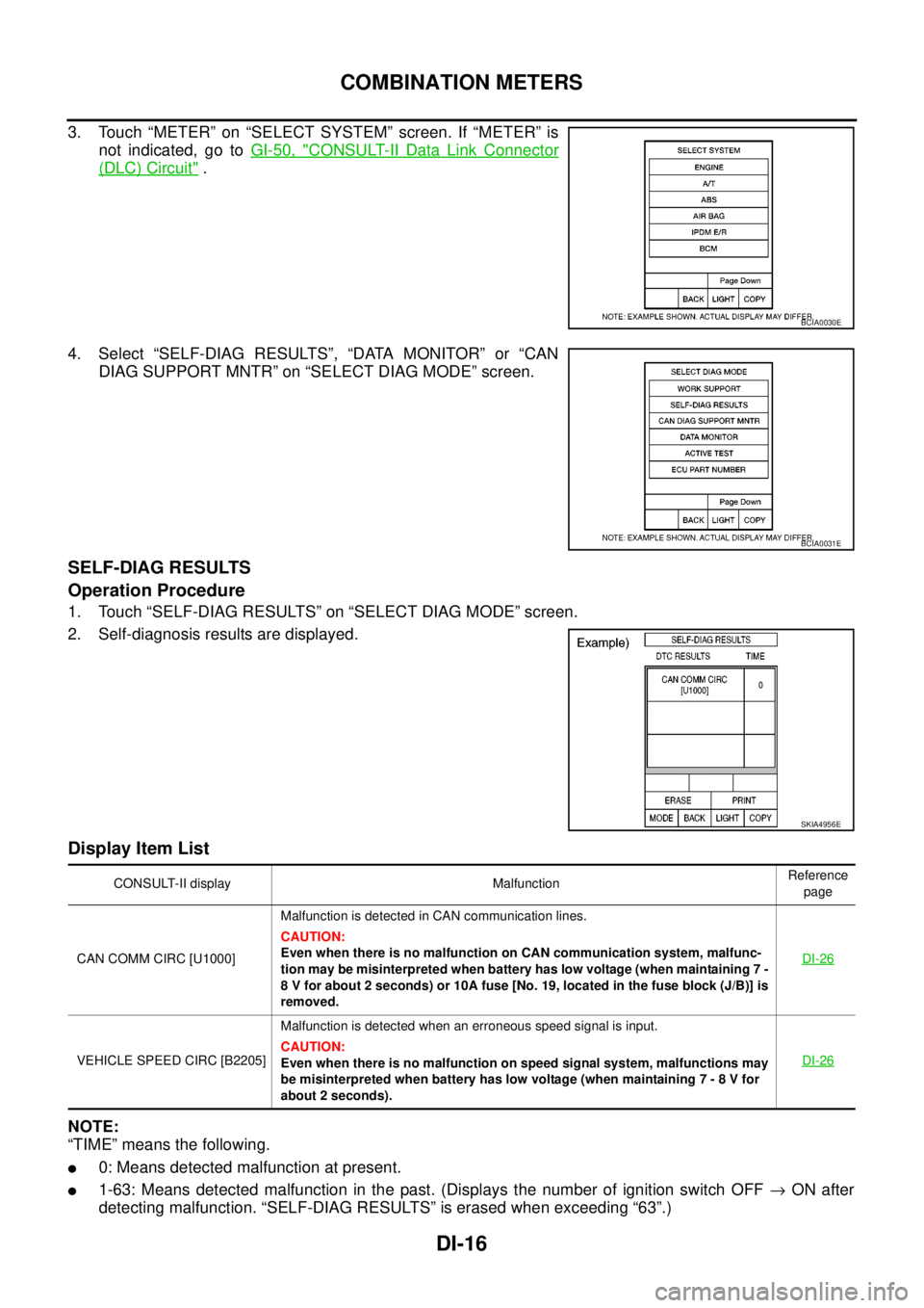
3. Touch “METER” on “SELECT SYSTEM” screen. If “METER” is
not indicated, go toGI-50, "
CONSULT-II Data Link Connector
(DLC) Circuit".
4. Select “SELF-DIAG RESULTS”, “DATA MONITOR” or “CAN
DIAG SUPPORT MNTR” on “SELECT DIAG MODE” screen.
SELF-DIAG RESULTS
Operation Procedure
1. Touch “SELF-DIAG RESULTS” on “SELECT DIAG MODE” screen.
2. Self-diagnosis results are displayed.
Display Item List
NOTE:
“TIME” means the following.
l0: Means detected malfunction at present.
l1-63: Means detected malfunction in the past. (Displays the number of ignition switch OFF®ON after
detecting malfunction. “SELF-DIAG RESULTS” is erased when exceeding “63”.)
BCIA0030E
BCIA0031E
SKIA4956E
CONSULT-II display MalfunctionReference
page
CAN COMM CIRC [U1000]Malfunction is detected in CAN communication lines.
CAUTION:
Even when there is no malfunction on CAN communication system, malfunc-
tion may be misinterpreted when battery has low voltage (when maintaining 7 -
8 V for about 2 seconds) or 10A fuse [No. 19, located in the fuse block (J/B)] is
removed.DI-26
VEHICLE SPEED CIRC [B2205]Malfunction is detected when an erroneous speed signal is input.
CAUTION:
Even when there is no malfunction on speed signal system, malfunctions may
be misinterpreted when battery has low voltage (when maintaining 7 - 8 V for
about 2 seconds).DI-26
Page 936 of 3171
DI-26
COMBINATION METERS
4.QUESTION 4
During driving, does the fuel gauge pointer move gradually toward EMPTY position?
YES >> Check the fuel level sensor unit. Refer toDI-27, "FUEL LEVEL SENSOR UNIT CHECK".
NO >> The float arm may interfere or bind with any of the components in the fuel tank.
DTC [U1000] CAN Communication CircuitEKS00L8X
Symptom: Displays “CAN COMM CIRC [U1000]” at the self-diagnosis result for combination meter.
1.CHECK CAN COMMUNICATION
1. Select “SELF-DIAG RESULTS” mode for “METER” with CONSULT-II.
2. Print out CONSULT-II screen.
>> Go to “LAN SYSTEM”. Refer toLAN-3, "
Precautions When Using CONSULT-II".
DTC [B2205] Vehicle Speed CircuitEKS00L8Y
Symptom: Displays “VEHICLE SPEED CIRC [B2205]” at the self-diagnosis result for combination meter.
Perform the ABS actuator and electric unit (control unit) self-diagnosis, and repair or replace malfunctioning
parts. Refer toBRC-17, "
CONSULT- II Functions".
Page 970 of 3171
DI-60
WARNING CHIME
4. During the operation check, touching “OFF” deactivates the operation.
Display Item List
SELF-DIAG RESULTS
Operation Procedure
1. Touch “BCM” on “SELECT TEST ITEM” screen.
2. Touch “SELF-DIAG RESULTS” on “SELECT DIAG MODE” screen.
3. Self-diagnosis results are displayed.
Display Item List
NOTE:
If “CAN communication [U1000]” is indicated, print the monitor item, and then go to “LAN System”. Refer to
LAN-3, "
Precautions When Using CONSULT-II".
Trouble DiagnosisEKS00L9I
HOW TO PERFORM TROUBLE DIAGNOSIS
1. Confirm the symptom and customer complaint.
2. Understand the outline of system. Refer toDI-51, "
System Description".
3. Perform the preliminary inspection. Refer toDI-60, "
PRELIMINARY INSPECTION".
4. Referring to trouble diagnosis chart, repair or replace the cause of the malfunction. Refer toDI-61,
"SYMPTOM CHART".
5. Does warning chime system operate normally? If it operates normally, GO TO 6. If not, GO TO 3.
6. INSPECTION END
PRELIMINARY INSPECTION
1.CHECK BCM (CONSULT-II)
Perform self-diagnosis of BCM.Refer toBCS-14, "
CONSULT-II Function (BCM)".
Self
-diagnosis results
No malfunction detected>>GO TO 2.
Malfunction detected>>Check applicable parts, and repair or replace corresponding parts.
2.CHECK COMBINATION METER (CONSULT-II)
Perform self-diagnosis of combination meter. Refer toDI-15, "
CONSULT-II Function (METER)".
Self
-diagnosis results
No malfunction detected>>INSPECTION END
Malfunction detected>>Check applicable parts, and repair or replace corresponding parts.
Test item Malfunction is detected when···
LIGHT WARN ALM This test is able to check light warning chime operation.
IGN KEY WARN ALM This test is able to check key warning chime operation.
KEY REMINDER WARN This test is able to check key reminder warning chime operation.
Monitored Item CONSULT-II display Description
CAN communication CAN communication [U1000] Malfunction is detected in CAN communication.
Page 981 of 3171
EC-1
ENGINE CONTROL SYSTEM
B ENGINE
CONTENTS
C
D
E
F
G
H
I
J
K
L
M
SECTIONEC
A
EC
ENGINE CONTROL SYSTEM
INDEX FOR DTC ........................................................ 6
DTC No. Index ......................................................... 6
Alphabetical Index .................................................... 8
PRECAUTIONS ........................................................ 10
Precautions for Supplemental Restraint System
(SRS)“AIRBAG”and“SEATBELTPRE-TEN-
SIONER” ................................................................ 10
On Board Diagnostic (OBD) System of Engine ...... 10
Precautions ............................................................ 10
Wiring Diagrams and Trouble Diagnosis ................ 13
PREPARATION ......................................................... 14
Special Service Tools ............................................. 14
Commercial Service Tools ...................................... 14
ENGINE CONTROL SYSTEM .................................. 15
System Diagram ..................................................... 15
Vacuum Hose Drawing ........................................... 16
System Chart ......................................................... 18
Fuel Injection Control System ................................ 18
Fuel Injection Timing Control System ..................... 20
Air Conditioning Cut Control ................................... 20
Fuel Cut Control (At No Load & High Engine Speed)... 20
Crankcase Ventilation System ............................... 21
CAN Communication .............................................. 22
BASIC SERVICE PROCEDURE .............................. 23
Fuel Filter ............................................................... 23
Fuel Pump Learning Value Clearing ...................... 24
Injector Adjustment Value Registration .................. 25
ON BOARD DIAGNOSTIC (OBD) SYSTEM ............ 27
DTC Detection Logic .............................................. 27
Diagnostic Trouble Code (DTC) ............................. 27
Freeze Frame Data ................................................ 28
NATS (Nissan Anti-theft System) ........................... 28
Malfunction Indicator (MI) ....................................... 28
Relationship Between MI, DTC, CONSULT-II and
Driving Patterns ...................................................... 31
TROUBLE DIAGNOSIS ............................................ 33
Trouble Diagnosis Introduction ............................... 33
DTC Inspection Priority Chart ................................ 37
Basic Inspection ..................................................... 38
Symptom Matrix Chart ........................................... 42Engine Control Component Parts Location ............ 46
Circuit Diagram ....................................................... 50
ECM Harness Connector Terminal Layout ............. 52
ECM Terminals And Reference Value .................... 52
CONSULT-II Function (ENGINE) ............................ 59
CONSULT-II Reference Value in Data Monitor Mode
... 66
Major Sensor Reference Graph in Data Monitor
Mode ....................................................................... 69
TROUBLE DIAGNOSIS FOR INTERMITTENT INCI-
DENT ......................................................................... 70
Description .............................................................. 70
Diagnostic Procedure ............................................. 70
POWER SUPPLY AND GROUND CIRCUIT ............. 71
ECM Terminals and Reference Value ..................... 71
Wiring Diagram ....................................................... 72
Diagnostic Procedure ............................................. 73
Ground Inspection .................................................. 78
DTC U1000 CAN COMMUNICATION LINE .............. 79
Description .............................................................. 79
On Board Diagnosis Logic ...................................... 79
DTC Confirmation Procedure ................................. 79
Wiring Diagram ....................................................... 80
Diagnostic Procedure ............................................. 81
DTC P0016 CKP - CMP CORRELATION ................. 82
On Board Diagnosis Logic ...................................... 82
DTC Confirmation Procedure ................................. 82
Diagnostic Procedure ............................................. 82
DTC P0088 FUEL SYSTEM ...................................... 84
On Board Diagnosis Logic ...................................... 84
DTC Confirmation Procedure ................................. 84
Diagnostic Procedure ............................................. 84
Removal and Installation ........................................ 85
DTC P0089 FUEL PUMP .......................................... 86
On Board Diagnosis Logic ...................................... 86
DTC Confirmation Procedure ................................. 86
Diagnostic Procedure ............................................. 87
Removal and Installation ........................................ 87
DTC P0093 FUEL SYSTEM ...................................... 88
On Board Diagnosis Logic ...................................... 88
Page 986 of 3171
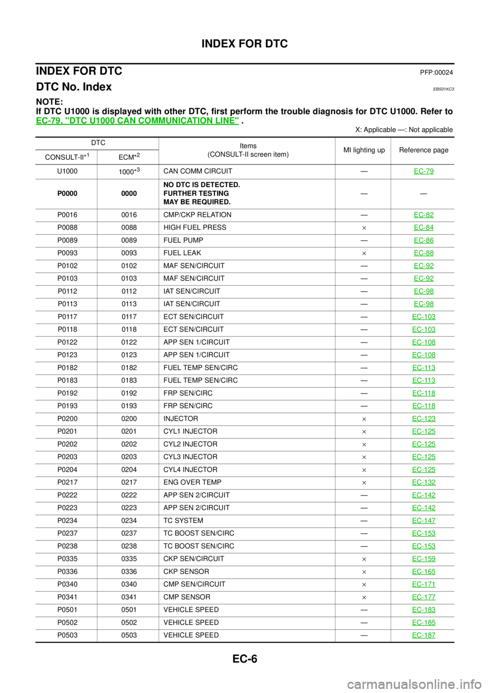
EC-6
INDEX FOR DTC
INDEX FOR DTC
PFP:00024
DTC No. IndexEBS01KC3
NOTE:
If DTC U1000 is displayed with other DTC, first perform the trouble diagnosis for DTC U1000. Refer to
EC-79, "
DTC U1000 CAN COMMUNICATION LINE".
X: Applicable —: Not applicable
DTC
Items
(CONSULT-II screen item)MI lighting up Reference page
CONSULT-II*
1ECM*2
U1000
1000*3CAN COMM CIRCUIT —EC-79
P0000 0000NO DTC IS DETECTED.
FURTHER TESTING
MAY BE REQUIRED.——
P0016 0016 CMP/CKP RELATION —EC-82
P0088 0088 HIGH FUEL PRESS´EC-84
P0089 0089 FUEL PUMP —EC-86
P0093 0093 FUEL LEAK´EC-88
P0102 0102 MAF SEN/CIRCUIT —EC-92
P0103 0103 MAF SEN/CIRCUIT —EC-92
P0112 0112 IAT SEN/CIRCUIT —EC-98
P0113 0113 IAT SEN/CIRCUIT —EC-98
P0117 0117 ECT SEN/CIRCUIT —EC-103
P0118 0118 ECT SEN/CIRCUIT —EC-103
P0122 0122 APP SEN 1/CIRCUIT —EC-108
P0123 0123 APP SEN 1/CIRCUIT —EC-108
P0182 0182 FUEL TEMP SEN/CIRC —EC-113
P0183 0183 FUEL TEMP SEN/CIRC —EC-113
P0192 0192 FRP SEN/CIRC —EC-118
P0193 0193 FRP SEN/CIRC —EC-118
P0200 0200 INJECTOR´EC-123
P0201 0201 CYL1 INJECTOR´EC-125
P0202 0202 CYL2 INJECTOR´EC-125
P0203 0203 CYL3 INJECTOR´EC-125
P0204 0204 CYL4 INJECTOR´EC-125
P0217 0217 ENG OVER TEMP´EC-132
P0222 0222 APP SEN 2/CIRCUIT —EC-142
P0223 0223 APP SEN 2/CIRCUIT —EC-142
P0234 0234 TC SYSTEM —EC-147
P0237 0237 TC BOOST SEN/CIRC —EC-153
P0238 0238 TC BOOST SEN/CIRC —EC-153
P0335 0335 CKP SEN/CIRCUIT´EC-159
P0336 0336 CKP SENSOR´EC-165
P0340 0340 CMP SEN/CIRCUIT´EC-171
P0341 0341 CMP SENSOR´EC-177
P0501 0501 VEHICLE SPEED —EC-183
P0502 0502 VEHICLE SPEED —EC-185
P0503 0503 VEHICLE SPEED —EC-187
Page 988 of 3171
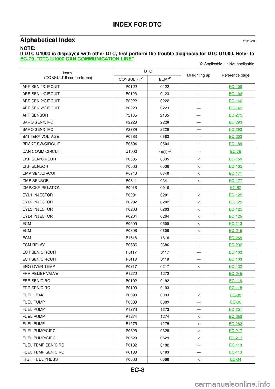
EC-8
INDEX FOR DTC
Alphabetical Index
EBS01KC4
NOTE:
If DTC U1000 is displayed with other DTC, first perform the trouble diagnosis for DTC U1000. Refer to
EC-79, "
DTC U1000 CAN COMMUNICATION LINE".
X: Applicable —: Not applicable
Items
(CONSULT-II screen terms)DTC
MI lighting up Reference page
CONSULT-II*
1ECM*2
APP SEN 1/CIRCUIT P0122 0122 —EC-108
APP SEN 1/CIRCUIT P0123 0123 —EC-108
APP SEN 2/CIRCUIT P0222 0222 —EC-142
APP SEN 2/CIRCUIT P0223 0223 —EC-142
APP SENSOR P2135 2135 —EC-275
BARO SEN/CIRC P2228 2228 —EC-293
BARO SEN/CIRC P2229 2229 —EC-293
BATTERY VOLTAGE P0563 0563 —EC-203
BRAKE SW/CIRCUIT P0504 0504 —EC-189
CAN COMM CIRCUIT U1000
1000*3—EC-79
CKP SEN/CIRCUIT P0335 0335´EC-159
CKP SENSOR P0336 0336´EC-165
CMP SEN/CIRCUIT P0340 0340´EC-171
CMP SENSOR P0341 0341´EC-177
CMP/CKP RELATION P0016 0016 —EC-82
CYL1 INJECTOR P0201 0201´EC-125
CYL2 INJECTOR P0202 0202´EC-125
CYL3 INJECTOR P0203 0203´EC-125
CYL4 INJECTOR P0204 0204´EC-125
ECM P0605 0605´EC-213
ECM P0606 0606´EC-215
ECM P1616 1616 —EC-269
ECM RELAY P0686 0686 —EC-232
ECT SEN/CIRCUIT P0117 0117 —EC-103
ECT SEN/CIRCUIT P0118 0118 —EC-103
ENG OVER TEMP P0217 0217´EC-132
FRP RELIEF VALVE P1272 1272 —EC-245
FRP SEN/CIRC P0192 0192 —EC-118
FRP SEN/CIRC P0193 0193 —EC-118
FUEL LEAK P0093 0093´EC-88
FUEL PUMP P0089 0089 —EC-86
FUEL PUMP P1273 1273 —EC-251
FUEL PUMP P1274 1274´EC-258
FUEL PUMP P1275 1275´EC-263
FUEL PUMP/CIRC P0628 0628´EC-217
FUEL PUMP/CIRC P0629 0629´EC-217
FUEL TEMP SEN/CIRC P0182 0182 —EC-113
FUEL TEMP SEN/CIRC P0183 0183 —EC-113
HIGH FUEL PRESS P0088 0088´EC-84
Page 1017 of 3171
TROUBLE DIAGNOSIS
EC-37
C
D
E
F
G
H
I
J
K
L
MA
EC
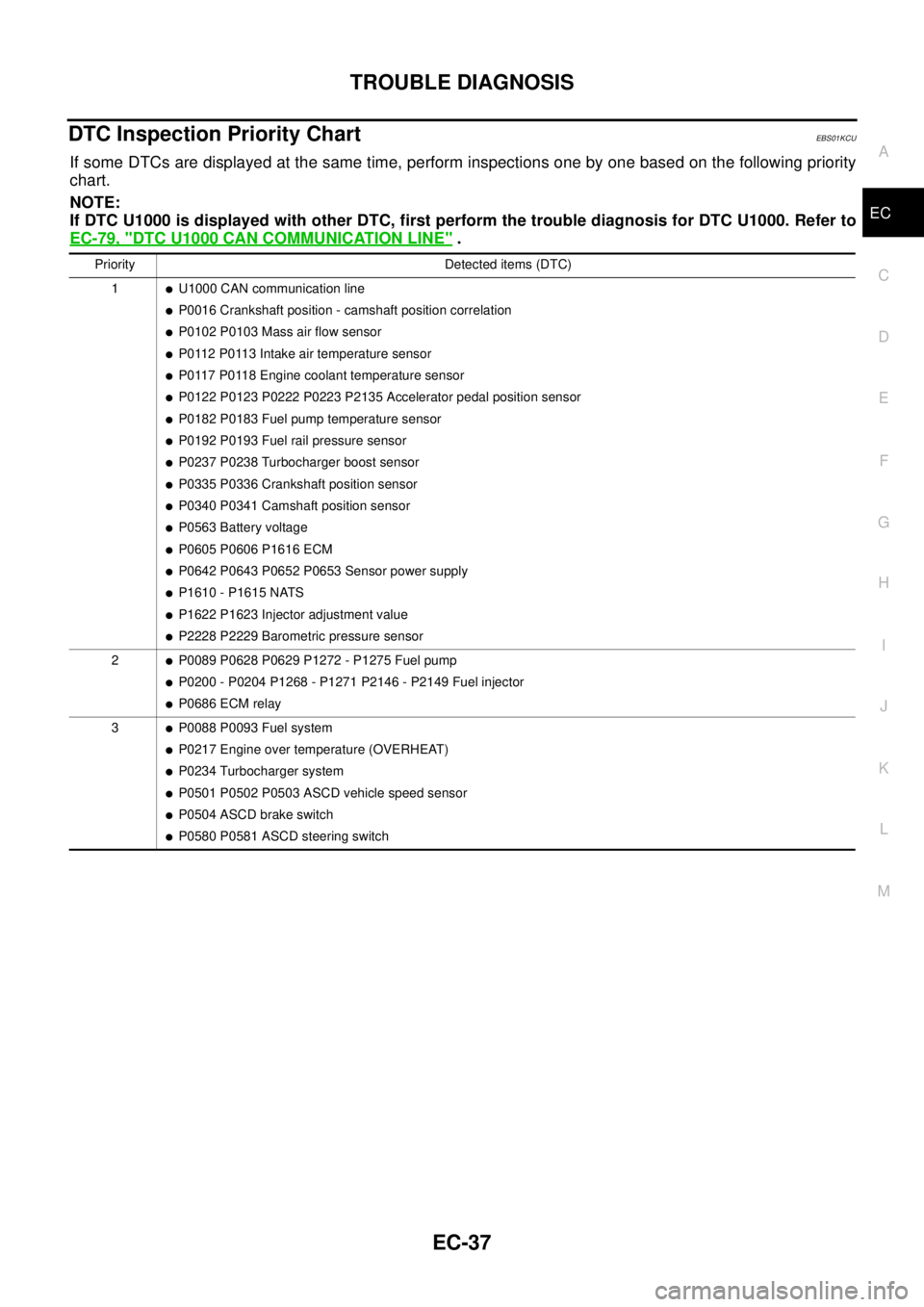
DTC Inspection Priority ChartEBS01KCU
If some DTCs are displayed at the same time, perform inspections one by one based on the following priority
chart.
NOTE:
If DTC U1000 is displayed with other DTC, first perform the trouble diagnosis for DTC U1000. Refer to
EC-79, "
DTC U1000 CAN COMMUNICATION LINE".
Priority Detected items (DTC)
1
lU1000 CAN communication line
lP0016 Crankshaft position - camshaft position correlation
lP0102 P0103 Mass air flow sensor
lP0112 P0113 Intake air temperature sensor
lP0117 P0118 Engine coolant temperature sensor
lP0122 P0123 P0222 P0223 P2135 Accelerator pedal position sensor
lP0182 P0183 Fuel pump temperature sensor
lP0192 P0193 Fuel rail pressure sensor
lP0237 P0238 Turbocharger boost sensor
lP0335 P0336 Crankshaft position sensor
lP0340 P0341 Camshaft position sensor
lP0563 Battery voltage
lP0605 P0606 P1616 ECM
lP0642 P0643 P0652 P0653 Sensor power supply
lP1610 - P1615 NATS
lP1622 P1623 Injector adjustment value
lP2228 P2229 Barometric pressure sensor
2
lP0089 P0628 P0629 P1272 - P1275 Fuel pump
lP0200 - P0204 P1268 - P1271 P2146 - P2149 Fuel injector
lP0686 ECM relay
3
lP0088 P0093 Fuel system
lP0217 Engine over temperature (OVERHEAT)
lP0234 Turbocharger system
lP0501 P0502 P0503 ASCD vehicle speed sensor
lP0504 ASCD brake switch
lP0580 P0581 ASCD steering switch
Page 1059 of 3171
DTC U1000 CAN COMMUNICATION LINE
EC-79
C
D
E
F
G
H
I
J
K
L
MA
EC
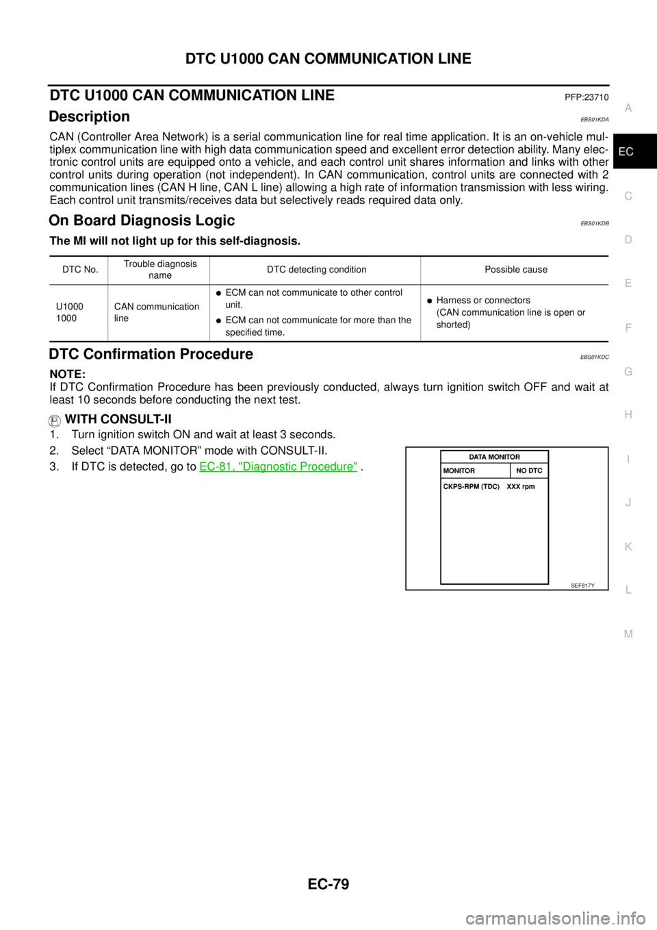
DTC U1000 CAN COMMUNICATION LINEPFP:23710
DescriptionEBS01KDA
CAN (Controller Area Network) is a serial communication line for real time application. It is an on-vehicle mul-
tiplex communication line with high data communication speed and excellent error detection ability. Many elec-
tronic control units are equipped onto a vehicle, and each control unit shares information and links with other
control units during operation (not independent). In CAN communication, control units are connected with 2
communication lines (CAN H line, CAN L line) allowing a high rate of information transmission with less wiring.
Each control unit transmits/receives data but selectively reads required data only.
On Board Diagnosis LogicEBS01KDB
The MI will not light up for this self-diagnosis.
DTC Confirmation ProcedureEBS01KDC
NOTE:
If DTC Confirmation Procedure has been previously conducted, always turn ignition switch OFF and wait at
least 10 seconds before conducting the next test.
WITH CONSULT-II
1. Turn ignition switch ON and wait at least 3 seconds.
2. Select “DATA MONITOR” mode with CONSULT-II.
3. If DTC is detected, go toEC-81, "
Diagnostic Procedure".
DTC No.Trouble diagnosis
nameDTC detecting condition Possible cause
U1000
1000CAN communication
line
lECM can not communicate to other control
unit.
lECM can not communicate for more than the
specified time.
lHarness or connectors
(CAN communication line is open or
shorted)
SEF817Y