Page 100 of 3171
AT-92
DTC U1000 CAN COMMUNICATION LINE
Wiring Diagram — AT — CAN
ECS00FXG
MCWA0194E
Page 101 of 3171
DTC U1000 CAN COMMUNICATION LINE
AT-93
D
E
F
G
H
I
J
K
L
MA
B
AT
Data are reference value and are measured between each terminal and ground.
Diagnostic ProcedureECS00FXH
1.CHECK CAN COMMUNICATION CIRCUIT
With CONSULT-II
1. Turn ignition switch ON and start engine.
2. Select “SELF-DIAG RESULTS” mode for “A/T” with CONSULT-
II.
Is any malfunction of the
“U1000 CAN COMM CIRCUIT”indicated?
YES >> Print out CONSULT-II screen, GO TO LAN section.
Refer toLAN-3, "
Precautions When Using CONSULT-II"
.
NO >>INSPECTION END
Terminal Wire color Item Condition Data (Approx.)
3 L CAN-H – –
8 P CAN-L – –
PCIA0061E
Page 117 of 3171
DTC P0725 ENGINE SPEED SIGNAL
AT-109
D
E
F
G
H
I
J
K
L
MA
B
AT
Diagnostic ProcedureECS00FYD
1.CHECK CAN COMMUNICATION LINE
Perform self-diagnosis. Refer toAT-80, "
SELF-DIAGNOSTIC RESULT MODE",AT-89, "Diagnostic Procedure
Without CONSULT-II".
Is a malfunction in the CAN communication indicated in the results?
YES >> Check CAN communication line. Refer toAT-91, "DTC U1000 CAN COMMUNICATION LINE".
NO >> GO TO 2.
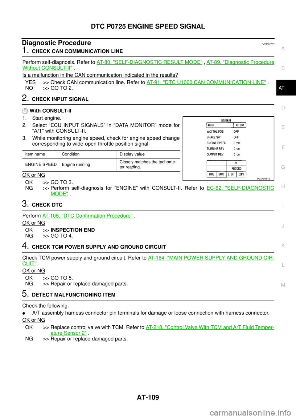
2.CHECK INPUT SIGNAL
With CONSULT-II
1. Start engine.
2. Select “ECU INPUT SIGNALS” in “DATA MONITOR” mode for
“A/T” with CONSULT-II.
3. While monitoring engine speed, check for engine speed change
corresponding to wide-open throttle position signal.
OK or NG
OK >> GO TO 3.
NG >> Perform self-diagnosis for “ENGINE” with CONSULT-II. Refer toEC-62, "
SELF-DIAGNOSTIC
MODE".
3.CHECK DTC
PerformAT- 1 0 8 , "
DTC Confirmation Procedure".
OK or NG
OK >>INSPECTION END
NG >> GO TO 4.
4.CHECK TCM POWER SUPPLY AND GROUND CIRCUIT
Check TCM power supply and ground circuit. Refer toAT- 1 6 4 , "
MAIN POWER SUPPLY AND GROUND CIR-
CUIT".
OK or NG
OK >> GO TO 5.
NG >> Repair or replace damaged parts.
5.DETECT MALFUNCTIONING ITEM
Check the following.
lA/T assembly harness connector pin terminals for damage or loose connection with harness connector.
OK or NG
OK >> Replace control valve with TCM. Refer toAT- 2 1 8 , "Control Valve With TCM and A/T Fluid Temper-
ature Sensor 2".
NG >> Repair or replace damaged parts.
Item name Condition Display value
ENGINE SPEED Engine runningClosely matches the tachome-
ter reading.
PCIA0041E
Page 124 of 3171
AT-116
DTC P1705 THROTTLE POSITION SENSOR
DTC P1705 THROTTLE POSITION SENSOR
PFP:22620
DescriptionECS00G43
The accelerator pedal position sensor sends a signal to ECM, and ECM sends signals to TCM with CAN com-
munication.
CONSULT-II Reference ValueECS00G44
On Board Diagnosis LogicECS00G45
Diagnostic trouble code “P1705 TP SEN/CIRC A/T” with CONSULT-II or 15th judgement flicker without CON-
SULT-II is detected when TCM does not receive the proper accelerator pedal position signals (input by CAN
communication) from ECM.
Possible CauseECS00G46
Harness or connectors
(The sensor circuit is open or shorted.)
DTC Confirmation ProcedureECS00G47
NOTE:
If “DTC Confirmation Procedure” has been previously performed, always turn ignition switch OFF and
wait at least 10 seconds before performing the next test.
After the repair, perform the following procedure to confirm the malfunction is eliminated.
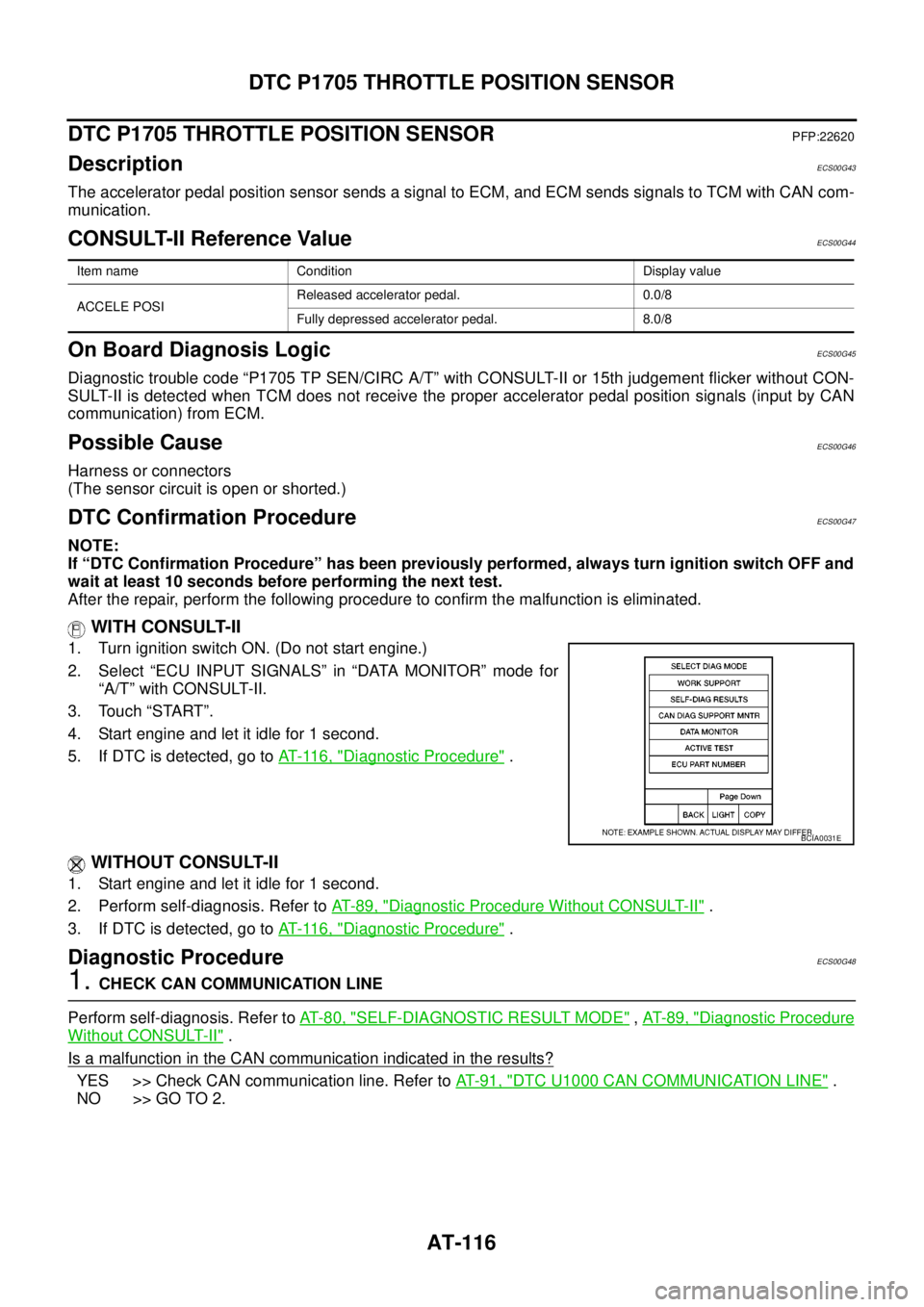
WITH CONSULT-II
1. Turn ignition switch ON. (Do not start engine.)
2. Select “ECU INPUT SIGNALS” in “DATA MONITOR” mode for
“A/T” with CONSULT-II.
3. Touch “START”.
4. Start engine and let it idle for 1 second.
5. If DTC is detected, go toAT- 11 6 , "
Diagnostic Procedure".
WITHOUT CONSULT-II
1. Start engine and let it idle for 1 second.
2. Perform self-diagnosis. Refer toAT-89, "
Diagnostic Procedure Without CONSULT-II".
3. If DTC is detected, go toAT- 11 6 , "
Diagnostic Procedure".
Diagnostic ProcedureECS00G48
1.CHECK CAN COMMUNICATION LINE
Perform self-diagnosis. Refer toAT-80, "
SELF-DIAGNOSTIC RESULT MODE",AT-89, "Diagnostic Procedure
Without CONSULT-II".
Is a malfunction in the CAN communication indicated in the results?
YES >> Check CAN communication line. Refer toAT-91, "DTC U1000 CAN COMMUNICATION LINE".
NO >> GO TO 2.
Item name Condition Display value
ACCELE POSIReleased accelerator pedal. 0.0/8
Fully depressed accelerator pedal. 8.0/8
BCIA0031E
Page 125 of 3171
DTC P1705 THROTTLE POSITION SENSOR
AT-117
D
E
F
G
H
I
J
K
L
MA
B
AT
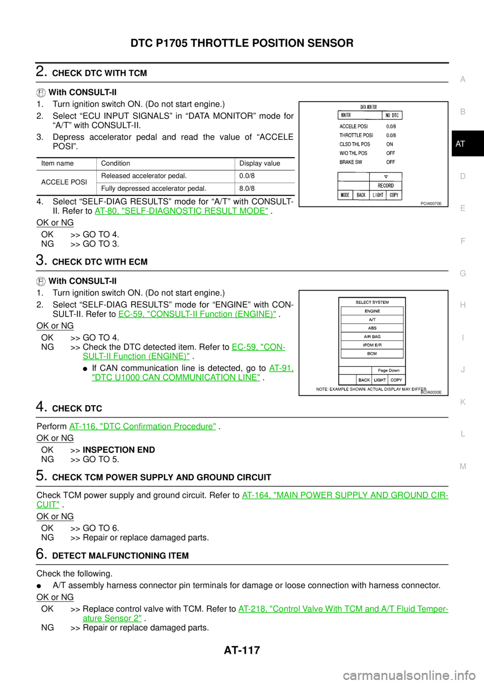
2.CHECK DTC WITH TCM
With CONSULT-II
1. Turn ignition switch ON. (Do not start engine.)
2. Select “ECU INPUT SIGNALS” in “DATA MONITOR” mode for
“A/T” with CONSULT-II.
3. Depress accelerator pedal and read the value of “ACCELE
POSI”.
4. Select “SELF-DIAG RESULTS” mode for “A/T” with CONSULT-
II. Refer toAT-80, "
SELF-DIAGNOSTIC RESULT MODE".
OK or NG
OK >> GO TO 4.
NG >> GO TO 3.
3.CHECK DTC WITH ECM
With CONSULT-II
1. Turn ignition switch ON. (Do not start engine.)
2. Select “SELF-DIAG RESULTS” mode for “ENGINE” with CON-
SULT-II. Refer toEC-59, "
CONSULT-II Function (ENGINE)".
OK or NG
OK >> GO TO 4.
NG >> Check the DTC detected item. Refer toEC-59, "
CON-
SULT-II Function (ENGINE)".
lIf CAN communication line is detected, go toAT- 9 1 ,
"DTC U1000 CAN COMMUNICATION LINE".
4.CHECK DTC
PerformAT- 11 6 , "
DTC Confirmation Procedure".
OK or NG
OK >>INSPECTION END
NG >> GO TO 5.
5.CHECK TCM POWER SUPPLY AND GROUND CIRCUIT
Check TCM power supply and ground circuit. Refer toAT- 1 6 4 , "
MAIN POWER SUPPLY AND GROUND CIR-
CUIT".
OK or NG
OK >> GO TO 6.
NG >> Repair or replace damaged parts.
6.DETECT MALFUNCTIONING ITEM
Check the following.
lA/T assembly harness connector pin terminals for damage or loose connection with harness connector.
OK or NG
OK >> Replace control valve with TCM. Refer toAT- 2 1 8 , "Control Valve With TCM and A/T Fluid Temper-
ature Sensor 2".
NG >> Repair or replace damaged parts.
Item name Condition Display value
ACCELE POSIReleased accelerator pedal. 0.0/8
Fully depressed accelerator pedal. 8.0/8
PCIA0070E
BCIA0030E
Page 134 of 3171
AT-126
DTC P1721 VEHICLE SPEED SENSOR MTR
Diagnostic Procedure
ECS00FZD
1.CHECK CAN COMMUNICATION LINE
Perform self-diagnosis. Refer toAT-80, "
SELF-DIAGNOSTIC RESULT MODE",AT-89, "Diagnostic Procedure
Without CONSULT-II".
Is malfunction in the CAN communication indicated in the result?
YES >> Check CAN communication line. Refer toAT-91, "DTC U1000 CAN COMMUNICATION LINE".
NO >> GO TO 2.
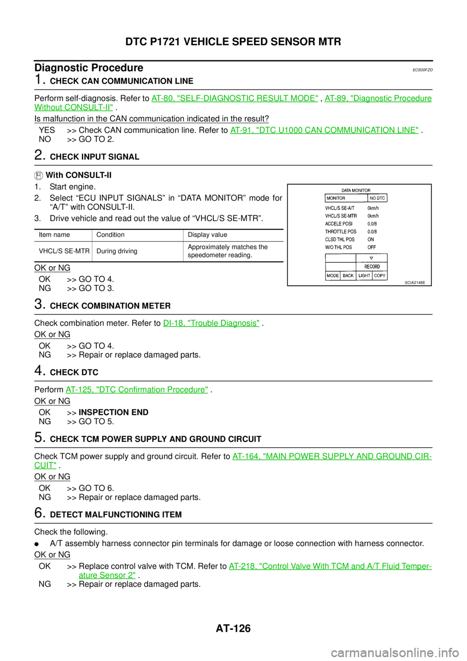
2.CHECK INPUT SIGNAL
With CONSULT-II
1. Start engine.
2. Select “ECU INPUT SIGNALS” in “DATA MONITOR” mode for
“A/T” with CONSULT-II.
3. Drive vehicle and read out the value of “VHCL/S SE-MTR”.
OK or NG
OK >> GO TO 4.
NG >> GO TO 3.
3.CHECK COMBINATION METER
Check combination meter. Refer toDI-18, "
Trouble Diagnosis".
OK or NG
OK >> GO TO 4.
NG >> Repair or replace damaged parts.
4.CHECK DTC
PerformAT- 1 2 5 , "
DTC Confirmation Procedure".
OK or NG
OK >>INSPECTION END
NG >> GO TO 5.
5.CHECK TCM POWER SUPPLY AND GROUND CIRCUIT
Check TCM power supply and ground circuit. Refer toAT- 1 6 4 , "
MAIN POWER SUPPLY AND GROUND CIR-
CUIT".
OK or NG
OK >> GO TO 6.
NG >> Repair or replace damaged parts.
6.DETECT MALFUNCTIONING ITEM
Check the following.
lA/T assembly harness connector pin terminals for damage or loose connection with harness connector.
OK or NG
OK >> Replace control valve with TCM. Refer toAT- 2 1 8 , "Control Valve With TCM and A/T Fluid Temper-
ature Sensor 2".
NG >> Repair or replace damaged parts.
Item name Condition Display value
VHCL/S SE-MTR During drivingApproximately matches the
speedometer reading.
SCIA2148E
Page 176 of 3171
AT-168
CLOSED THROTTLE POSITION AND WIDE OPEN THROTTLE POSITION CIR-
CUIT
CLOSED THROTTLE POSITION AND WIDE OPEN THROTTLE POSITION CIR-
CUIT
PFP:18002
CONSULT-II Reference ValueECS00G24
Diagnostic ProcedureECS00G25
1.CHECK CAN COMMUNICATION LINE
Perform self-diagnosis. Refer toAT-80, "
SELF-DIAGNOSTIC RESULT MODE",AT-89, "Diagnostic Procedure
Without CONSULT-II".
Is a malfunction in the CAN communication indicated in the results?
YES >> Check CAN communication line. Refer toAT-91, "DTC U1000 CAN COMMUNICATION LINE".
NO >> GO TO 2.
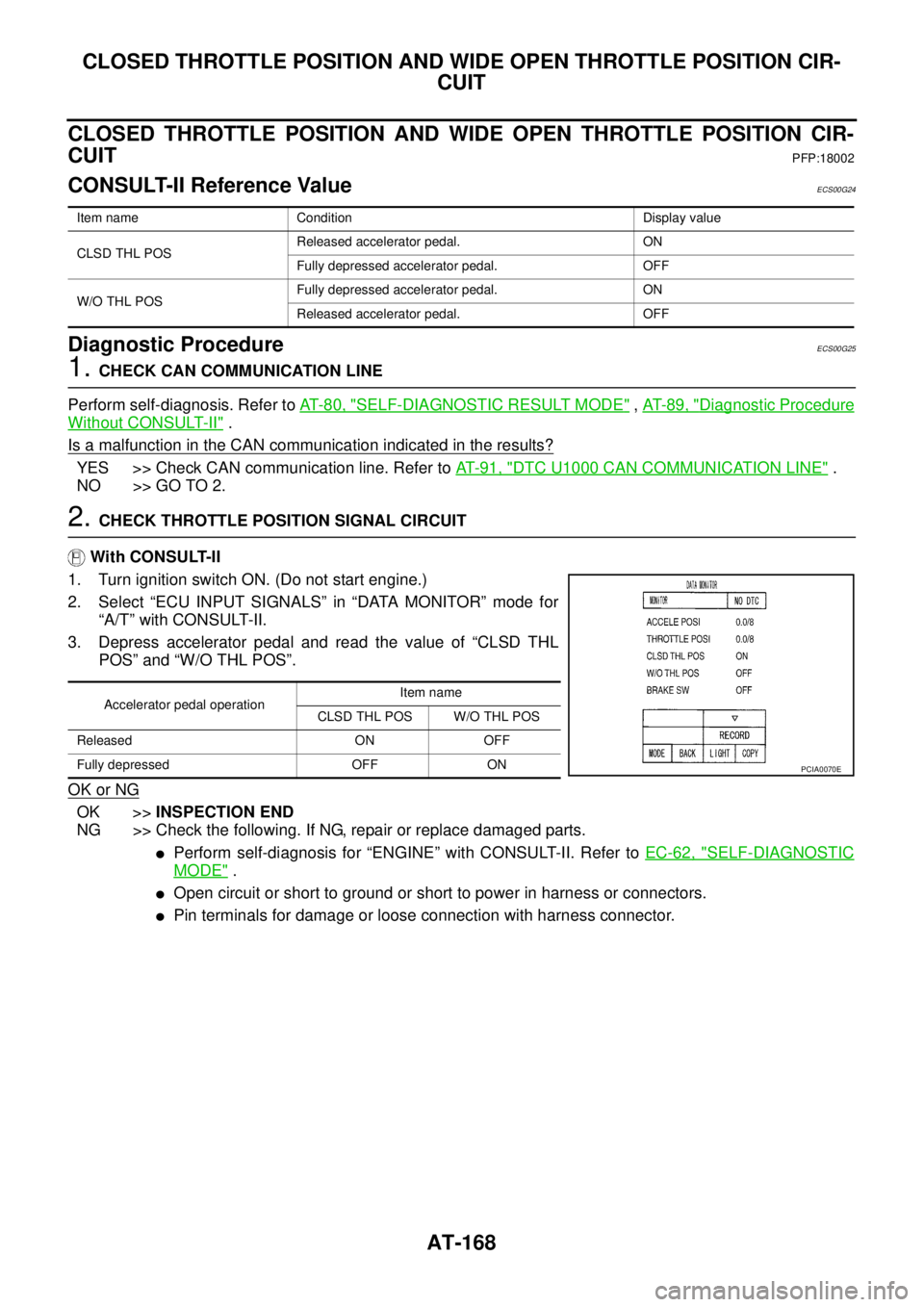
2.CHECK THROTTLE POSITION SIGNAL CIRCUIT
With CONSULT-II
1. Turn ignition switch ON. (Do not start engine.)
2. Select “ECU INPUT SIGNALS” in “DATA MONITOR” mode for
“A/T” with CONSULT-II.
3. Depress accelerator pedal and read the value of “CLSD THL
POS” and “W/O THL POS”.
OK or NG
OK >>INSPECTION END
NG >> Check the following. If NG, repair or replace damaged parts.
lPerform self-diagnosis for “ENGINE” with CONSULT-II. Refer toEC-62, "SELF-DIAGNOSTIC
MODE".
lOpen circuit or short to ground or short to power in harness or connectors.
lPin terminals for damage or loose connection with harness connector.
Item name Condition Display value
CLSD THL POSReleased accelerator pedal. ON
Fully depressed accelerator pedal. OFF
W/O THL POSFully depressed accelerator pedal. ON
Released accelerator pedal. OFF
Accelerator pedal operationItem name
CLSD THL POS W/O THL POS
Released ON OFF
Fully depressed OFF ON
PCIA0070E
Page 177 of 3171

BRAKE SIGNAL CIRCUIT
AT-169
D
E
F
G
H
I
J
K
L
MA
B
AT
BRAKE SIGNAL CIRCUITPFP:25320
CONSULT-II Reference ValueECS00G26
Diagnostic ProcedureECS00G27
1.CHECK CAN COMMUNICATION LINE
Perform self-diagnosis. Refer toAT-80, "
SELF-DIAGNOSTIC RESULT MODE",AT-89, "Diagnostic Procedure
Without CONSULT-II".
Is a malfunction in the CAN communication indicated in the results?
YES >> Check CAN communication line. Refer toAT-91, "DTC U1000 CAN COMMUNICATION LINE".
NO >> GO TO 2.
2.CHECK STOP LAMP SWITCH CIRCUIT
With CONSULT-II
1. Turn ignition switch ON. (Do not start engine.)
2. Select “ECU INPUT SIGNALS” in “DATA MONITOR” mode for
“A/T” with CONSULT-II.
3. Read the ON/OFF switching action of “BRAKE SW”.
OK or NG
OK >>INSPECTION END
NG >> GO TO 3.
3.CHECK STOP LAMP SWITCH
Check continuity between stop lamp switch harness connector E109
terminals 1 and 2. Refer toAT- 1 7 4 , "
Wiring Diagram—AT—NON-
DTC".
Check stop lamp switch after adjusting brake pedal — refer to
BR-6, "
BRAKE PEDAL".
OK or NG
OK >> Check the following. If NG, repair or replace damaged
parts.
lHarness for short or open between battery and stop lamp switch.
lHarness for short or open between stop lamp switch and combination meter.
l10A fuse (No.20, located in fuse block).
NG >> Repair or replace stop lamp switch.
Item name Condition Display value
BRAKE SWDepressed brake pedal. ON
Released brake pedal. OFF
Item name Condition Display value
BRAKE SWDepressed brake pedal. ON
Released brake pedal. OFF
PCIA0070E
Condition Continuity
When brake pedal is depressed Yes
When brake pedal is released No
SCIA2144E