Page 1060 of 3171
EC-80
DTC U1000 CAN COMMUNICATION LINE
Wiring Diagram
EBS01KDD
MBWA1035E
Page 1061 of 3171
DTC U1000 CAN COMMUNICATION LINE
EC-81
C
D
E
F
G
H
I
J
K
L
MA
EC
Diagnostic ProcedureEBS01KDE
Go toLAN-3, "Precautions When Using CONSULT-II".
Page 1112 of 3171

EC-132
DTC P0217 ENGINE OVER TEMPERATURE
DTC P0217 ENGINE OVER TEMPERATURE
PFP:21481
DescriptionEBS01KFK
SYSTEM DESCRIPTION
NOTE:
If DTC P0217 is displayed with DTC U1000, first perform the trouble diagnosis for DTC U1000. Refer to
EC-79, "
DTC U1000 CAN COMMUNICATION LINE".
Cooling Fan Control
*: This signal is sent to ECM through CAN communication line.
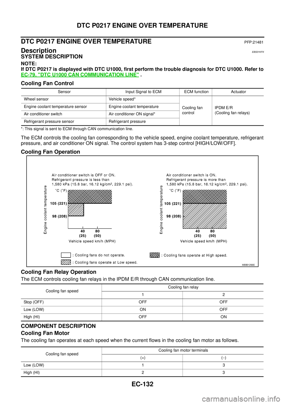
The ECM controls the cooling fan corresponding to the vehicle speed, engine coolant temperature, refrigerant
pressure, and air conditioner ON signal. The control system has 3-step control [HIGH/LOW/OFF].
Cooling Fan Operation
Cooling Fan Relay Operation
The ECM controls cooling fan relays in the IPDM E/R through CAN communication line.
COMPONENT DESCRIPTION
Cooling Fan Motor
The cooling fan operates at each speed when the current flows in the cooling fan motor as follows.
Sensor Input Signal to ECM ECM function Actuator
Wheel sensor Vehicle speed*
Cooling fan
controlIPDM E/R
(Cooling fan relays) Engine coolant temperature sensor Engine coolant temperature
Air conditioner switch Air conditioner ON signal*
Refrigerant pressure sensor Refrigerant pressure
MBIB1266E
Cooling fan speedCooling fan relay
12
Stop (OFF) OFF OFF
Low (LOW) ON OFF
High (HI) OFF ON
Cooling fan speedCooling fan motor terminals
(+) (-)
Low (LOW) 1 3
High (HI) 2 3
Page 1163 of 3171

DTC P0501 ASCD VEHICLE SPEED SENSOR
EC-183
C
D
E
F
G
H
I
J
K
L
MA
EC
DTC P0501 ASCD VEHICLE SPEED SENSORPFP:24810
Component DescriptionEBS01KHH
The ECM receives vehicle speed sensor signal via CAN communication line. It is sent from combination
meter. The ECM uses this signal for ASCD control. Refer toEC-355, "
AUTOMATIC SPEED CONTROL
DEVICE (ASCD)"for ASCD functions.
On Board Diagnosis LogicEBS01KHI
The MI will not light up for this self-diagnosis.
NOTE:
lIf DTC P0501 is displayed with DTC U1000 first perform the trouble diagnosis for DTC U1000. Refer
toEC-79, "
DTC U1000 CAN COMMUNICATION LINE".
lIf DTC P0501 is displayed with DTC P0606, first perform the trouble diagnosis for DTC P0606.
Refer toEC-215, "
DTC P0606 ECM".
DTC Confirmation ProcedureEBS01KHJ
CAUTION:
Always drive vehicle at a safe speed.
NOTE:
If DTC Confirmation Procedure has been previously conducted, always turn ignition switch OFF and wait at
least 10 seconds before conducting the next test.
TESTING CONDITION:
Step 3 may be conducted with the drive wheels lifted in the shop or by driving the vehicle. If a road test
is expected to be easier, it is unnecessary to lift the vehicle.
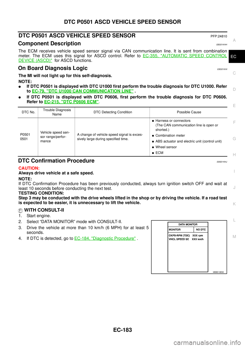
WITH CONSULT-II
1. Start engine.
2. Select “DATA MONITOR” mode with CONSULT-II.
3. Drive the vehicle at more than 10 km/h (6 MPH) for at least 5
seconds.
4. If DTC is detected, go toEC-184, "
Diagnostic Procedure".
DTC No.Trouble Diagnosis
NameDTC Detecting Condition Possible Cause
P0501
0501Vehicle speed sen-
sor range/perfor-
manceA change of vehicle speed signal is exces-
sively large during specified time.
lHarness or connectors
(The CAN communication line is open or
shorted.)
lCombination meter
lABS actuator and electric unit (control unit)
lWheel sensor
lECM
SEF058YMBIB1085E
Page 1165 of 3171

DTC P0502 ASCD VEHICLE SPEED SENSOR
EC-185
C
D
E
F
G
H
I
J
K
L
MA
EC
DTC P0502 ASCD VEHICLE SPEED SENSORPFP:24810
Component DescriptionEBS01KHL
The ECM receives vehicle speed sensor signal via CAN communication line. It is sent from combination
meter. The ECM uses this signal for ASCD control. Refer toEC-355, "
AUTOMATIC SPEED CONTROL
DEVICE (ASCD)"for ASCD functions.
On Board Diagnosis LogicEBS01KHM
The MI will not light up for this self-diagnosis.
NOTE:
lIf DTC P0502 is displayed with DTC U1000 first perform the trouble diagnosis for DTC U1000. Refer
toEC-79, "
DTC U1000 CAN COMMUNICATION LINE".
lIf DTC P0502 is displayed with DTC P0606, first perform the trouble diagnosis for DTC P0606.
Refer toEC-215, "
DTC P0606 ECM".
DTC Confirmation ProcedureEBS01KHN
CAUTION:
Always drive vehicle at a safe speed.
NOTE:
If DTC Confirmation Procedure has been previously conducted, always turn ignition switch OFF and wait at
least 10 seconds before conducting the next test.
TESTING CONDITION:
Step 3 may be conducted with the drive wheels lifted in the shop or by driving the vehicle. If a road test
is expected to be easier, it is unnecessary to lift the vehicle.
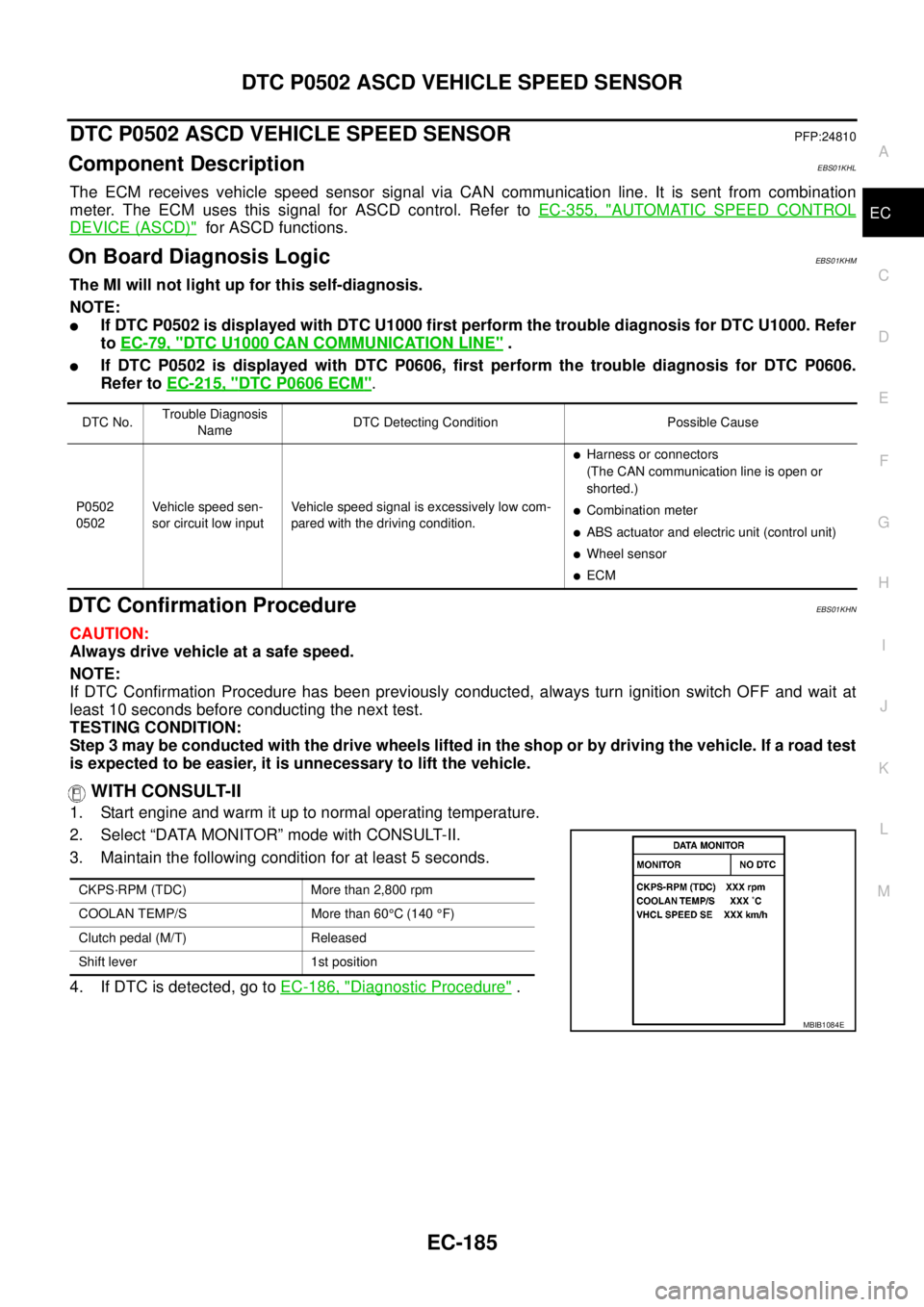
WITH CONSULT-II
1. Start engine and warm it up to normal operating temperature.
2. Select “DATA MONITOR” mode with CONSULT-II.
3. Maintain the following condition for at least 5 seconds.
4. If DTC is detected, go toEC-186, "
Diagnostic Procedure".
DTC No.Trouble Diagnosis
NameDTC Detecting Condition Possible Cause
P0502
0502Vehicle speed sen-
sor circuit low inputVehicle speed signal is excessively low com-
pared with the driving condition.
lHarness or connectors
(The CAN communication line is open or
shorted.)
lCombination meter
lABS actuator and electric unit (control unit)
lWheel sensor
lECM
CKPS·RPM (TDC) More than 2,800 rpm
COOLAN TEMP/S More than 60°C (140°F)
Clutch pedal (M/T) Released
Shift lever 1st position
MBIB1084E
Page 1167 of 3171

DTC P0503 ASCD VEHICLE SPEED SENSOR
EC-187
C
D
E
F
G
H
I
J
K
L
MA
EC
DTC P0503 ASCD VEHICLE SPEED SENSORPFP:24810
Component DescriptionEBS01KHP
The ECM receives vehicle speed sensor signal via CAN communication line. It is sent from combination
meter. The ECM uses this signal for ASCD control. Refer toEC-355, "
AUTOMATIC SPEED CONTROL
DEVICE (ASCD)"for ASCD functions.
On Board Diagnosis LogicEBS01KHQ
The MI will not light up for this self-diagnosis.
NOTE:
lIf DTC P0503 is displayed with DTC U1000 first perform the trouble diagnosis for DTC U1000. Refer
toEC-79, "
DTC U1000 CAN COMMUNICATION LINE".
lIf DTC P0503 is displayed with DTC P0606, first perform the trouble diagnosis for DTC P0606.
Refer toEC-215, "
DTC P0606 ECM".
DTC Confirmation ProcedureEBS01KHR
CAUTION:
Always drive vehicle at a safe speed.
NOTE:
If DTC Confirmation Procedure has been previously conducted, always turn ignition switch OFF and wait at
least 10 seconds before conducting the next test.
TESTING CONDITION:
Step 3 may be conducted with the drive wheels lifted in the shop or by driving the vehicle. If a road test
is expected to be easier, it is unnecessary to lift the vehicle.
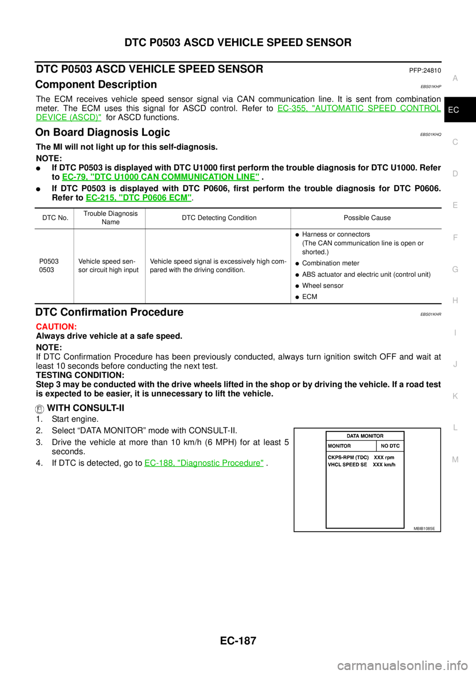
WITH CONSULT-II
1. Start engine.
2. Select “DATA MONITOR” mode with CONSULT-II.
3. Drive the vehicle at more than 10 km/h (6 MPH) for at least 5
seconds.
4. If DTC is detected, go toEC-188, "
Diagnostic Procedure".
DTC No.Trouble Diagnosis
NameDTC Detecting Condition Possible Cause
P0503
0503Vehicle speed sen-
sor circuit high inputVehicle speed signal is excessively high com-
pared with the driving condition.
lHarness or connectors
(The CAN communication line is open or
shorted.)
lCombination meter
lABS actuator and electric unit (control unit)
lWheel sensor
lECM
SEF058YMBIB1085E
Page 1279 of 3171
GLOW CONTROL SYSTEM
EC-299
C
D
E
F
G
H
I
J
K
L
MA
EC
5.CHECK DTC
Check that DTC U1000 is not displayed.
Ye s o r N o
Yes >> Perform trouble diagnoses for DTC U1000, refer toEC-79, "DTC U1000 CAN COMMUNICATION
LINE".
No >> GO TO 6.
6.CHECK COMBINATON METER OPERATION
Does combination meter operate normally?
Ye s o r N o
Ye s > > G O T O 1 4 .
No >> Check combination meter circuit. Refer toDI-4, "
COMBINATION METERS".
7.CHECK GLOW RELAY POWER SUPPLY CIRCUIT
1. Turn ignition switch OFF.
2. Disconnect glow relay (1).
3. Check voltage between glow relay terminals 1, 3 and ground
with CONSULT-II or tester.
OK or NG
OK >> GO TO 9.
NG >> GO TO 8.
8.DETECT MALFUNCTIONING PART
Check the following.
l60A fusible link
lHarness for open or short between glow relay and battery
>> Repair harness or connectors.
MBIB1220E
Voltage: Battery voltage
PBIB1413E
Page 1333 of 3171
ASCD INDICATOR
EC-353
C
D
E
F
G
H
I
J
K
L
MA
EC
Diagnostic ProcedureEBS01KN0
1.CHECK OVERALL FUNCTION
Check ASCD indicator under the following conditions.
OK or NG
OK >>INSPECTION END
NG >> GO TO 2.
2.CHECK DTC
Check that DTC U1000 is not displayed.
OK or NG
OK >> Perform trouble diagnoses for DTC U1000. Refer toEC-79, "DTC U1000 CAN COMMUNICA-
TION LINE".
NG >> GO TO 3.
3.CHECK COMBINATION METER OPERATION
Does combination meter operate normally?
Ye s o r N o
Ye s > > G O T O 4 .
No >> Check combination meter circuit. Refer toDI-4, "
COMBINATION METERS".
4.CHECK INTERMITTENT INCIDENT
Refer toEC-70, "
TROUBLE DIAGNOSIS FOR INTERMITTENT INCIDENT".
>>INSPECTION END
ASCD INDICATOR CONDITION SPECIFICATION
CRUISE LAMP
lIgnition switch: ONlMAIN switch: Pressed at the
first time®at the 2nd timeON®OFF
SET LAMP
lMAIN switch: ON
lWhen vehicle speed is
between 40 km/h (25 MPH)
and185km/h(115MPH)
lASCD: Operating ON
lASCD: Not operating OFF