2005 NISSAN NAVARA U1000
[x] Cancel search: U1000Page 178 of 3171
AT-170
1ST POSITION SWITCH
1ST POSITION SWITCH
PFP:31918
CONSULT-II Reference ValueECS00I5W
Diagnostic ProcedureECS00I5X
1.CHECK CAN COMMUNICATION LINE
Perform the self-diagnosis. Refer toAT-80, "
SELF-DIAGNOSTIC RESULT MODE".
Is any malfunction in the CAN communication indicated in the results?
YES >> Check CAN communication line. Refer toAT-91, "DTC U1000 CAN COMMUNICATION LINE".
NO >> GO TO 2.
2.CHECK 1ST POSITION SWITCH CIRCUIT
With CONSULT-II
1. Turn ignition switch ON.
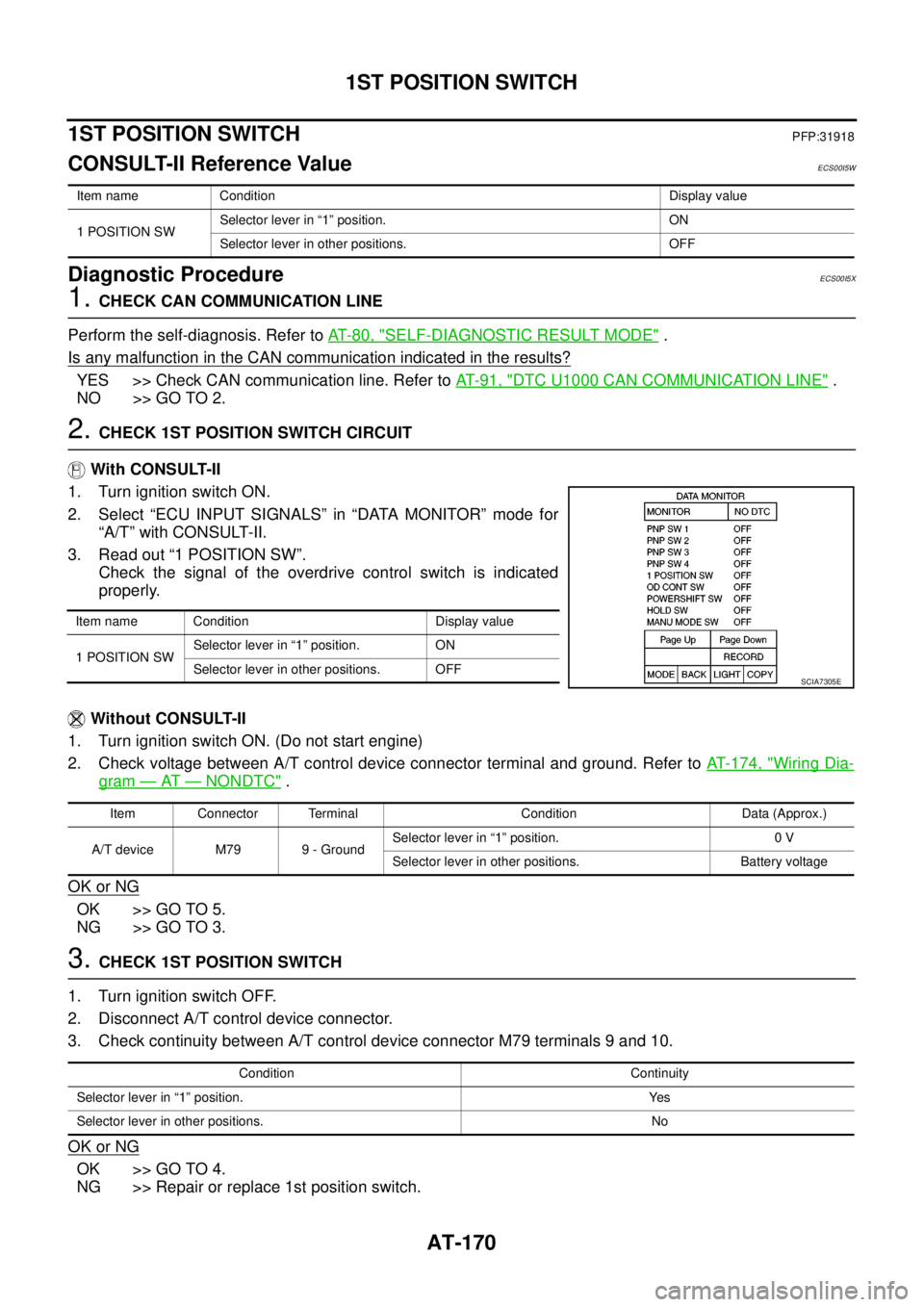
2. Select “ECU INPUT SIGNALS” in “DATA MONITOR” mode for
“A/T” with CONSULT-II.
3. Read out “1 POSITION SW”.
Check the signal of the overdrive control switch is indicated
properly.
Without CONSULT-II
1. Turn ignition switch ON. (Do not start engine)
2. Check voltage between A/T control device connector terminal and ground. Refer toAT- 1 7 4 , "
Wiring Dia-
gram—AT—NONDTC".
OK or NG
OK >> GO TO 5.
NG >> GO TO 3.
3.CHECK 1ST POSITION SWITCH
1. Turn ignition switch OFF.
2. Disconnect A/T control device connector.
3. Check continuity between A/T control device connector M79 terminals 9 and 10.
OK or NG
OK >> GO TO 4.
NG >> Repair or replace 1st position switch.
Item name Condition Display value
1 POSITION SWSelector lever in “1” position. ON
Selector lever in other positions. OFF
Item name Condition Display value
1 POSITION SWSelector lever in “1” position. ON
Selector lever in other positions. OFF
SCIA7305E
Item Connector Terminal Condition Data (Approx.)
A/T device M79 9 - GroundSelector lever in “1” position. 0 V
Selector lever in other positions. Battery voltage
Condition Continuity
Selector lever in “1” position. Yes
Selector lever in other positions. No
Page 180 of 3171
AT-172
OVERDRIVE CONTROL SWITCH
OVERDRIVE CONTROL SWITCH
PFP:25130
CONSULT-II Reference ValueECS00HQY
Diagnostic ProcedureECS00HQZ
1.CHECK CAN COMMUNICATION LINE
Perform the self-diagnosis. Refer toAT-80, "
SELF-DIAGNOSTIC RESULT MODE".
Is any malfunction in the CAN communication indicated in the results?
YES >> Check CAN communication line. Refer toAT-91, "DTC U1000 CAN COMMUNICATION LINE".
NO >> GO TO 2.
2.CHECK OVERDRIVE CONTOROL SWITCH CIRCUIT
With CONSULT-II
1. Turn ignition switch ON.
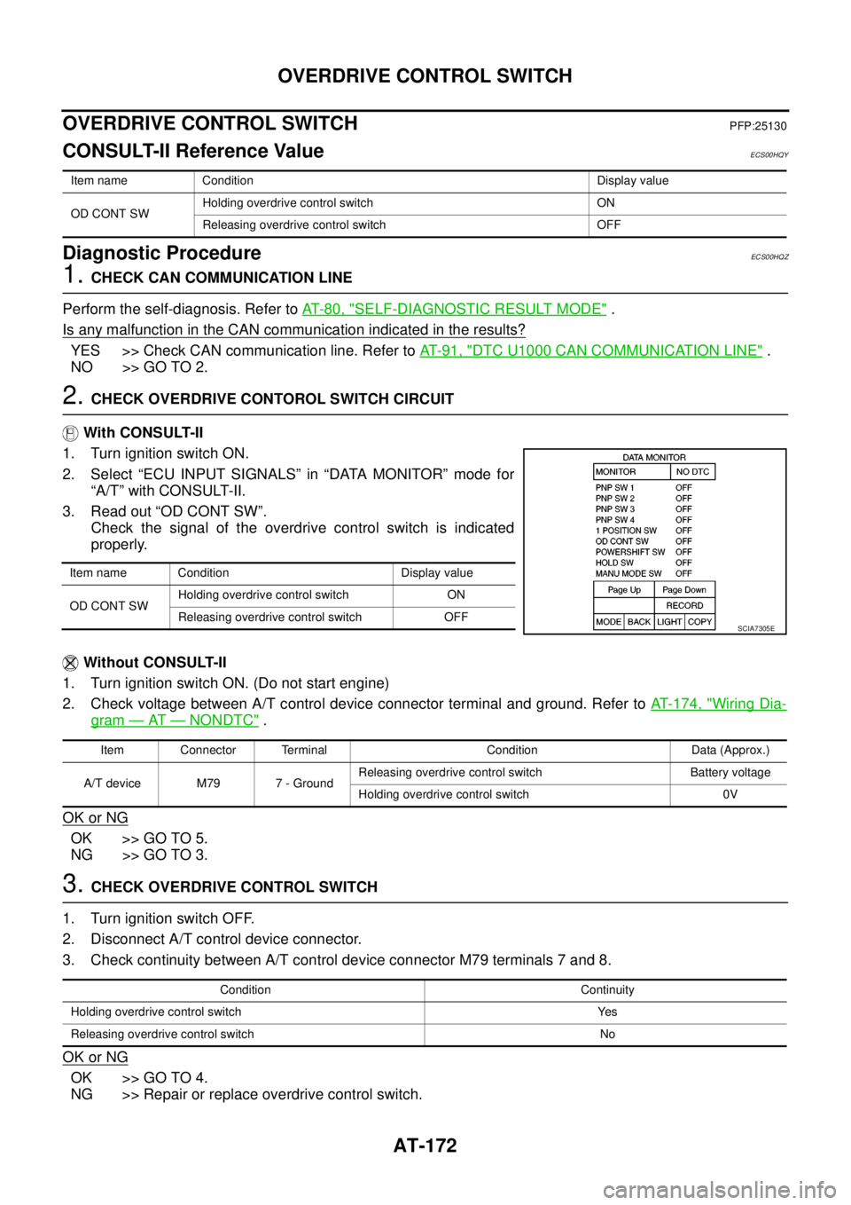
2. Select “ECU INPUT SIGNALS” in “DATA MONITOR” mode for
“A/T” with CONSULT-II.
3. Read out “OD CONT SW”.
Check the signal of the overdrive control switch is indicated
properly.
Without CONSULT-II
1. Turn ignition switch ON. (Do not start engine)
2. Check voltage between A/T control device connector terminal and ground. Refer toAT- 1 7 4 , "
Wiring Dia-
gram—AT—NONDTC".
OK or NG
OK >> GO TO 5.
NG >> GO TO 3.
3.CHECK OVERDRIVE CONTROL SWITCH
1. Turn ignition switch OFF.
2. Disconnect A/T control device connector.
3. Check continuity between A/T control device connector M79 terminals 7 and 8.
OK or NG
OK >> GO TO 4.
NG >> Repair or replace overdrive control switch.
Item name Condition Display value
OD CONT SWHolding overdrive control switch ON
Releasing overdrive control switch OFF
Item name Condition Display value
OD CONT SWHolding overdrive control switch ON
Releasing overdrive control switch OFF
SCIA7305E
Item Connector Terminal Condition Data (Approx.)
A/T device M79 7 - GroundReleasing overdrive control switch Battery voltage
Holding overdrive control switch 0V
Condition Continuity
Holding overdrive control switch Yes
Releasing overdrive control switch No
Page 185 of 3171
TROUBLE DIAGNOSIS FOR SYMPTOMS
AT-177
D
E
F
G
H
I
J
K
L
MA
B
AT
Data are reference value and are measured between each terminal and ground.
OD OFF Indicator Lamp Does Not Come OnECS00G2B
SYMPTOM:
OD OFF indicator lamp does not come on for about 2 seconds when turning ignition switch ON.
DIAGNOSTIC PROCEDURE
1.CHECK CAN COMMUNICATION LINE
Perform self-diagnosis. Refer toAT-80, "
SELF-DIAGNOSTIC RESULT MODE",AT-89, "Diagnostic Procedure
Without CONSULT-II".
Is a malfunction in the CAN communication indicated in the results?
YES >> Check CAN communication line. Refer toAT-91, "DTC U1000 CAN COMMUNICATION LINE".
NO >> GO TO 2.
2.CHECK OD OFF INDICATOR LAMP CIRCUIT
Check combination meter. Refer toDI-4, "
COMBINATION METERS".
OK or NG
OK >> GO TO 3
NG >> Repair or replace damaged parts.
3.CHECK TCM POWER SUPPLY AND GROUND CIRCUIT
Check TCM power supply and ground circuit. Refer toAT- 1 6 4 , "
MAIN POWER SUPPLY AND GROUND CIR-
CUIT".
OK or NG
OK >>INSPECTION END
NG >> Repair or replace damaged parts.
Engine Cannot Be Started in “P” or “N” PositionECS00G2C
SYMPTOM:
lEngine cannot be started with selector lever in “P” or “N” position.
lEngine can be started with selector lever in “R”, “D”, “3”, “2” or “1” position.
DIAGNOSTIC PROCEDURE
1.CHECK SELF-DIAGNOSIS RESULTS
Perform self-diagnosis. Refer toAT-80, "
SELF-DIAGNOSTIC RESULT MODE",AT-89, "Diagnostic Procedure
Without CONSULT-II".
Do the self-diagnosis results indicate PNP switch?
YES >> Check malfunctioning system. Refer toAT-99, "DTC P0705 PARK/NEUTRAL POSITION
SWITCH".
NO >> GO TO 2.
TerminalWire
colorItem Condition Data (Approx.)
3 L CAN-H – –
4GRK-line (CONSULT-
II signal)The terminal is connected to the data link connector for CONSULT-II. –
7LGBack-up lamp
relaySelector lever in “R” position. 0V
Selector lever in other positions. Battery voltage
8 P CAN-L – –
9BRStarterrelaySelector lever in “N” or “P” position. Battery voltage
Selector lever in other positions. 0V
Page 544 of 3171
AV-56
DIAGNOSIS SYSTEM
CONSULT-II Functions
EKS00Q6L
CONSULT-II FUNCTIONS
CONSULT-II can display each diagnostic item using the diagnostic test modes shown following.
CONSULT-II BASIC OPERATION PROCEDURE
CAUTION:
If CONSULT-II is used with no connection of CONSULT-II CONVERTER, malfunctions might be
detected in self-diagnosis depending on control unit which carry out CAN communication.
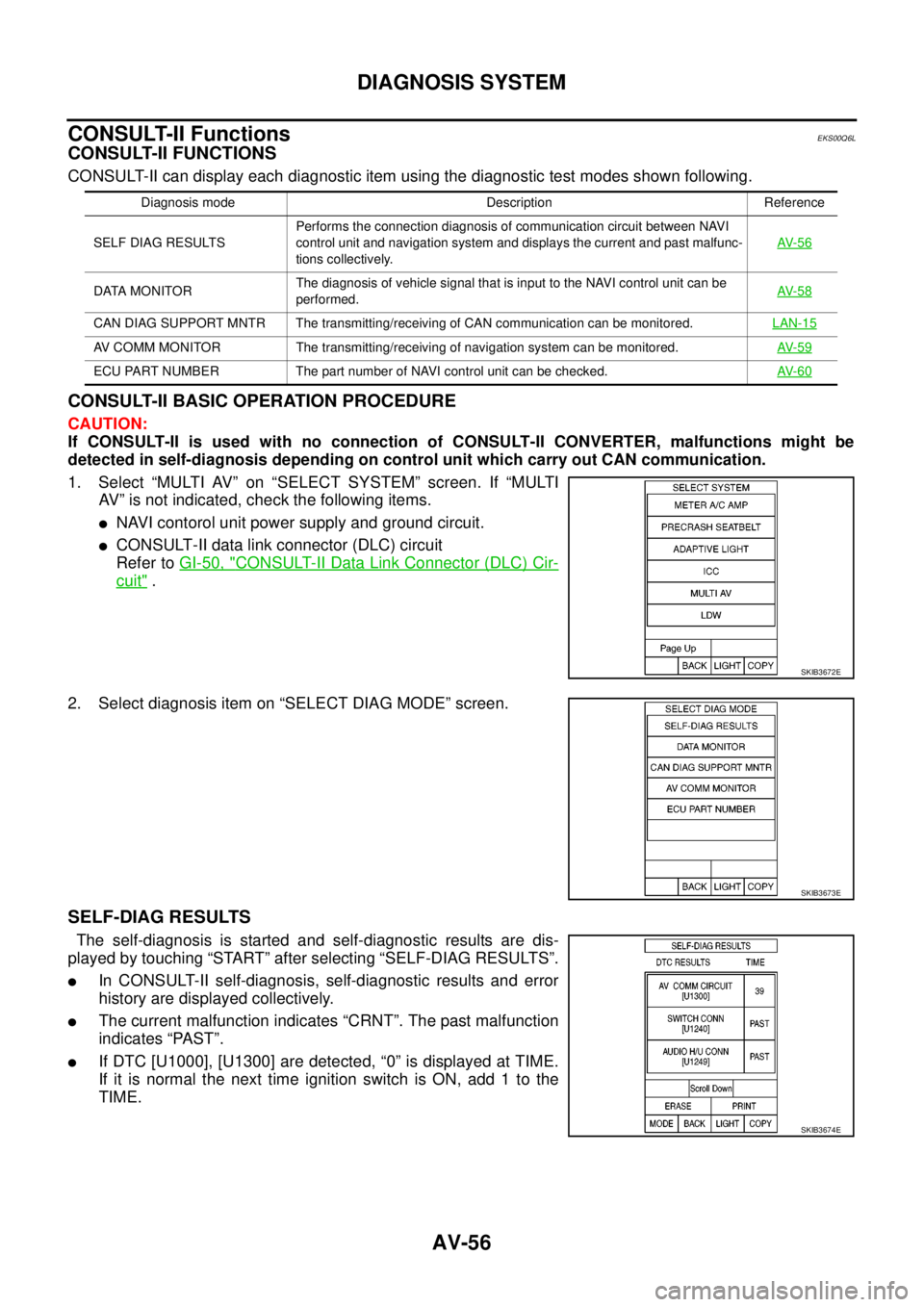
1. Select “MULTI AV” on “SELECT SYSTEM” screen. If “MULTI
AV” is not indicated, check the following items.
lNAVI contorol unit power supply and ground circuit.
lCONSULT-II data link connector (DLC) circuit
Refer toGI-50, "
CONSULT-II Data Link Connector (DLC) Cir-
cuit".
2. Select diagnosis item on “SELECT DIAG MODE” screen.
SELF-DIAG RESULTS
The self-diagnosis is started and self-diagnostic results are dis-
played by touching “START” after selecting “SELF-DIAG RESULTS”.
lIn CONSULT-II self-diagnosis, self-diagnostic results and error
history are displayed collectively.
lThe current malfunction indicates “CRNT”. The past malfunction
indicates “PAST”.
lIf DTC [U1000], [U1300] are detected, “0” is displayed at TIME.
If it is normal the next time ignition switch is ON, add 1 to the
TIME.
Diagnosis mode Description Reference
SELF DIAG RESULTSPerforms the connection diagnosis of communication circuit between NAVI
control unit and navigation system and displays the current and past malfunc-
tions collectively.AV- 5 6
DATA MONITORThe diagnosis of vehicle signal that is input to the NAVI control unit can be
performed.AV- 5 8
CAN DIAG SUPPORT MNTR The transmitting/receiving of CAN communication can be monitored.LAN-15
AV COMM MONITOR The transmitting/receiving of navigation system can be monitored.AV- 5 9
ECU PART NUMBER The part number of NAVI control unit can be checked.AV- 6 0
SKIB3672E
SKIB3673E
SKIB3674E
Page 545 of 3171
DIAGNOSIS SYSTEM
AV-57
C
D
E
F
G
H
I
J
L
MA
B
AV
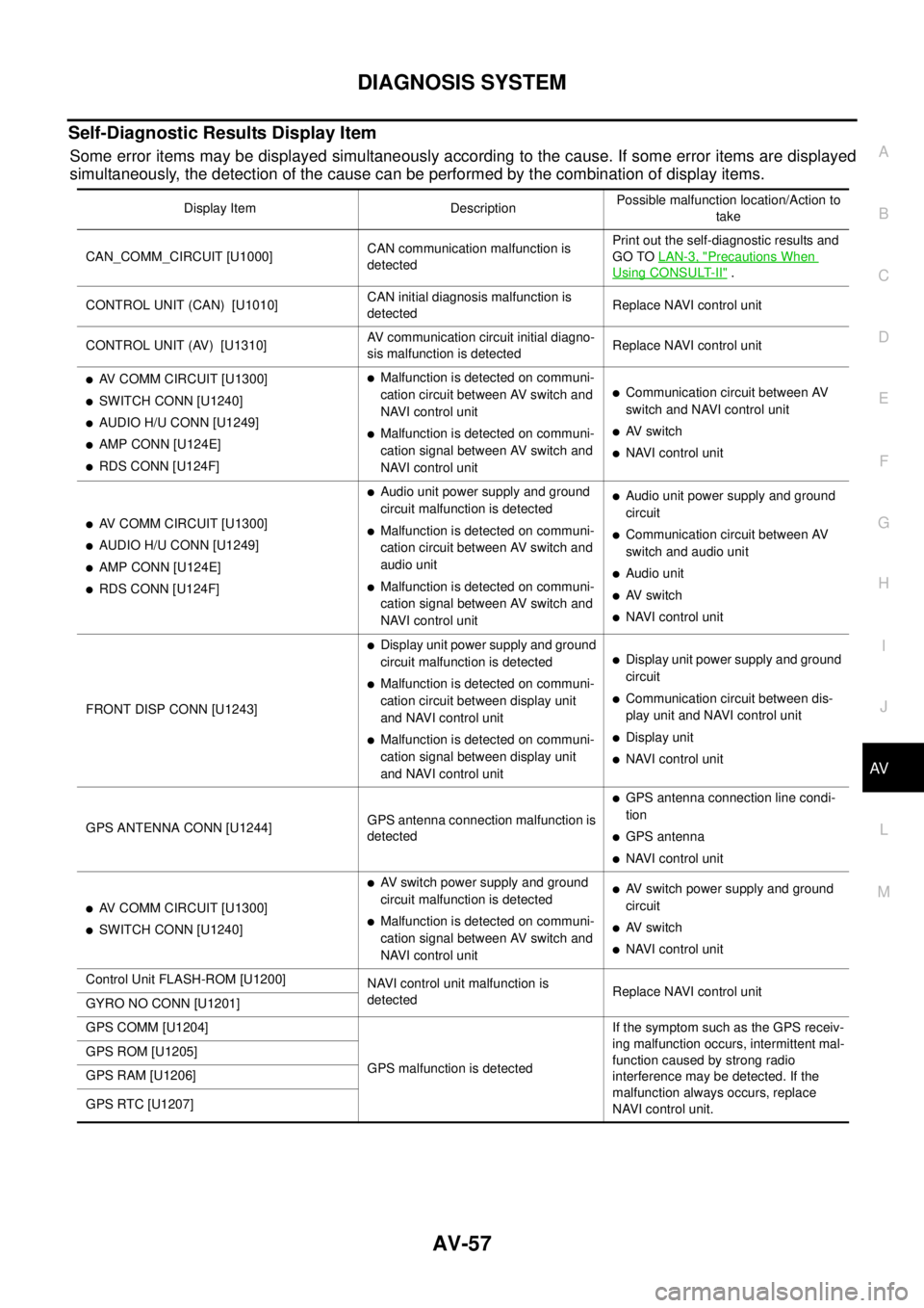
Self-Diagnostic Results Display Item
Some error items may be displayed simultaneously according to the cause. If some error items are displayed
simultaneously, the detection of the cause can be performed by the combination of display items.
Display Item DescriptionPossible malfunction location/Action to
take
CAN_COMM_CIRCUIT [U1000]CAN communication malfunction is
detectedPrint out the self-diagnostic results and
GO TOLAN-3, "
Precautions When
Using CONSULT-II".
CONTROL UNIT (CAN) [U1010]CAN initial diagnosis malfunction is
detectedReplace NAVI control unit
CONTROL UNIT (AV) [U1310]AV communication circuit initial diagno-
sis malfunction is detectedReplace NAVI control unit
lAV COMM CIRCUIT [U1300]
lSWITCH CONN [U1240]
lAUDIO H/U CONN [U1249]
lAMP CONN [U124E]
lRDS CONN [U124F]
lMalfunction is detected on communi-
cation circuit between AV switch and
NAVI control unit
lMalfunction is detected on communi-
cation signal between AV switch and
NAVI control unit
lCommunication circuit between AV
switch and NAVI control unit
lAV switch
lNAVI control unit
lAV COMM CIRCUIT [U1300]
lAUDIO H/U CONN [U1249]
lAMP CONN [U124E]
lRDS CONN [U124F]
lAudio unit power supply and ground
circuit malfunction is detected
lMalfunction is detected on communi-
cation circuit between AV switch and
audio unit
lMalfunction is detected on communi-
cation signal between AV switch and
NAVI control unit
lAudio unit power supply and ground
circuit
lCommunication circuit between AV
switch and audio unit
lAudio unit
lAV switch
lNAVI control unit
FRONT DISP CONN [U1243]
lDisplay unit power supply and ground
circuit malfunction is detected
lMalfunction is detected on communi-
cation circuit between display unit
and NAVI control unit
lMalfunction is detected on communi-
cation signal between display unit
and NAVI control unit
lDisplay unit power supply and ground
circuit
lCommunication circuit between dis-
play unit and NAVI control unit
lDisplay unit
lNAVI control unit
GPS ANTENNA CONN [U1244]GPS antenna connection malfunction is
detected
lGPS antenna connection line condi-
tion
lGPS antenna
lNAVI control unit
lAV COMM CIRCUIT [U1300]
lSWITCH CONN [U1240]
lAV switch power supply and ground
circuit malfunction is detected
lMalfunction is detected on communi-
cation signal between AV switch and
NAVI control unit
lAV switch power supply and ground
circuit
lAV switch
lNAVI control unit
Control Unit FLASH-ROM [U1200]
NAVI control unit malfunction is
detectedReplace NAVI control unit
GYRO NO CONN [U1201]
GPS COMM [U1204]
GPS malfunction is detectedIf the symptom such as the GPS receiv-
ing malfunction occurs, intermittent mal-
function caused by strong radio
interference may be detected. If the
malfunction always occurs, replace
NAVI control unit. GPS ROM [U1205]
GPS RAM [U1206]
GPS RTC [U1207]
Page 582 of 3171
BCS-16
BCM (BODY CONTROL MODULE)
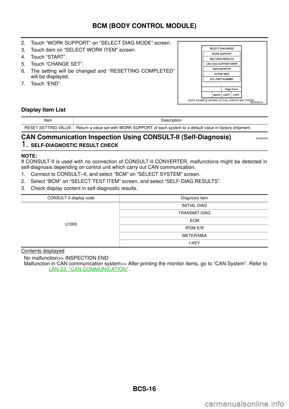
2. Touch “WORK SUPPORT” on “SELECT DIAG MODE” screen.
3. Touch item on “SELECT WORK ITEM” screen.
4. Touch “START”.
5. Touch “CHANGE SET”.
6. The setting will be changed and “RESETTING COMPLETED”
will be displayed.
7. Touch “END”.
Display Item List
CAN Communication Inspection Using CONSULT-II (Self-Diagnosis)EKS00PA5
1.SELF-DIAGNOSTIC RESULT CHECK
NOTE:
If CONSULT-II is used with no connection of CONSULT-II CONVERTER, malfunctions might be detected in
self-diagnosis depending on control unit which carry out CAN communication.
1. Connect to CONSULT–II, and select “BCM” on “SELECT SYSTEM” screen.
2. Select “BCM” on “SELECT TEST ITEM” screen, and select “SELF-DIAG RESULTS”.
3. Check display content in self-diagnostic results.
Contents displayed
No malfunction>> INSPECTION END
Malfunction in CAN communication system>> After printing the monitor items, go to “CAN System”. Refer to
LAN-23, "
CAN COMMUNICATION".
BCIA0031E
Item Description
RESET SETTING VALUE Return a value set with WORK SUPPORT of each system to a default value in factory shipment.
CONSULT-II display code Diagnosis item
U1000INITIAL DIAG
TRANSMIT DIAG
ECM
IPDM E/R
METER/M&A
I-KEY
Page 841 of 3171
![NISSAN NAVARA 2005 Repair Workshop Manual TROUBLE DIAGNOSIS
BRC-19
[ABS]
C
D
E
G
H
I
J
K
L
MA
B
BRC
Note 1: After completing repairs of shorted sensor circuit, when ignition switch is turned ON, ABS warning lamp turns on. Make sure that
ABS w NISSAN NAVARA 2005 Repair Workshop Manual TROUBLE DIAGNOSIS
BRC-19
[ABS]
C
D
E
G
H
I
J
K
L
MA
B
BRC
Note 1: After completing repairs of shorted sensor circuit, when ignition switch is turned ON, ABS warning lamp turns on. Make sure that
ABS w](/manual-img/5/57362/w960_57362-840.png)
TROUBLE DIAGNOSIS
BRC-19
[ABS]
C
D
E
G
H
I
J
K
L
MA
B
BRC
Note 1: After completing repairs of shorted sensor circuit, when ignition switch is turned ON, ABS warning lamp turns on. Make sure that
ABS warning lamp turns off while driving vehicle at 30 km/h (19 MPH) or more for approximately 1 minute according to self-diagnosis
procedure. In addition, if wheel sensor 2 is displayed for wheels, check wheel sensor circuit and also check control unit power voltage.
Note 2: When errors are detected in several systems, including CAN communication system [U1000], troubleshoot CAN communication
circuit. Refer toBRC-28, "
Inspection 4 CAN Communication Circuit". BATTERY VOLTAGE
[MALFUNCTION]ABS actuator and electric unit (control unit) power voltage is too low.BRC-28, "
Inspection 5
ABS Actuator and Elec-
tric Unit (Control Unit)
Power Supply and
Ground Circuit"
CONTROLLER FAILURE Internal malfunction of ABS actuator and electric unit (control unit)BRC-26, "
Inspection 2
ABS Actuator and Elec-
tric Unit (Control Unit)"
PUMP MOTORDuring actuator motor operation with ON, when actuator motor turns
OFF or when control line for actuator motor relay is open.BRC-26, "
Inspection 3
ABS Actuator Relay or
ABS Motor Relay Cir-
cuit"During actuator motor operation with OFF, when actuator motor
turns ON or when control line for relay is shorted to ground.
ABS SENSOR
[MALFUNCTION SIGNAL]Wheel sensor input is malfunction.BRC-24, "
Inspection 1
Wheel Sensor System"
(Note 1)
FR LH IN ABS SOLWhen the control unit detects an error in the front LH inlet solenoid
circuit.
BRC-26, "
Inspection 3
ABS Actuator Relay or
ABS Motor Relay Cir-
cuit"
FR LH OUT ABS SOLWhen the control unit detects an error in the front LH outlet solenoid
circuit.
FR RH IN ABS SOLWhen the control unit detects an error in the front RH inlet solenoid
circuit.
FR RH OUT ABS SOLWhen the control unit detects an error in the front RH outlet solenoid
circuit.
RR LH IN ABS SOLWhen the control unit detects an error in the rear LH inlet solenoid
circuit.
RR LH OUT ABS SOLWhen the control unit detects an error in the rear LH outlet solenoid
circuit.
RR RH IN ABS SOLWhen the control unit detects an error in the rear RH inlet solenoid
circuit.
RR RH OUT ABS SOLWhen the control unit detects an error in the rear RH outlet solenoid
circuit.
ACTUATOR RLY When the control unit detects an error in the actuator relay circuit.
CAN COMM CIRCUIT
[U1000]When there is an error in the CAN communications.BRC-28, "
Inspection 4
CAN Communication
Circuit"(Note 2) Self-diagnostic item Malfunction detecting condition Check system
Page 911 of 3171

DI-1
DRIVER INFORMATION SYSTEM
K ELECTRICAL
CONTENTS
C
D
E
F
G
H
I
J
L
M
SECTIONDI
A
B
DI
DRIVER INFORMATION SYSTEM
PRECAUTION ............................................................ 3
Precautions for Supplemental Restraint System
(SRS)“AIRBAG”and“SEATBELTPRE-TEN-
SIONER” .................................................................. 3
Wiring Diagrams and Trouble Diagnosis .................. 3
COMBINATION METERS ........................................... 4
System Description .................................................. 4
UNIFIED METER CONTROL UNIT ...................... 4
POWER SUPPLY AND GROUND CIRCUIT ........ 4
SPEEDOMETER ................................................... 4
TACHOMETER ..................................................... 4
WATER TEMPERATURE GAUGE ........................ 4
FUEL GAUGE ....................................................... 5
ODO/TRIP METER ............................................... 5
TRIP COMPUTER ................................................ 5
ENGINE OIL MAINTENANCE INFORMATION..... 6
METER ILLUMINATION CONTROL ..................... 6
CLOCK .................................................................. 6
AMBIENT AIR TEMPERATURE INDICATION ...... 6
Component Parts and Harness Connector Location..... 7
Arrangement of Combination Meter ......................... 8
Internal Circuit .......................................................... 9
Wiring Diagram — METER — ................................ 10
Terminals and Reference Value for Combination
Meter ...................................................................... 12
Self-Diagnosis Mode of Combination Meter ........... 13
FUNCTION .......................................................... 13
OPERATION PROCEDURE ............................... 13
TEST ITEM ......................................................... 13
CONSULT-II Function (METER) ............................. 15
CONSULT-II BASIC OPERATION ....................... 15
SELF-DIAG RESULTS ........................................ 16
DATA MONITOR ................................................. 17
Trouble Diagnosis .................................................. 18
HOW TO PERFORM TROUBLE DIAGNOSIS ... 18
PRELIMINARY CHECK ...................................... 19
Symptom Chart ...................................................... 19
Power Supply and Ground Circuit Inspection ........ 19
Vehicle Speed Signal Inspection ............................ 20
Engine Speed Signal Inspection ............................ 21Engine Coolant Temperature Signal Inspection ..... 21
Fuel Level Sensor Signal Inspection ...................... 22
Ambient Sensor Signal Inspection .......................... 24
Fuel Gauge Fluctuates, Indicates Wrong Value, or
Varies ...................................................................... 25
Fuel Gauge Does Not Move to Full position ........... 25
DTC [U1000] CAN Communication Circuit ............. 26
DTC [B2205] Vehicle Speed Circuit ........................ 26
Electrical Components Inspection .......................... 27
FUEL LEVEL SENSOR UNIT CHECK ................ 27
AMBIENT SENSOR CHECK ............................... 27
Removal and Installation of Combination Meter ..... 27
WARNING LAMPS .................................................... 28
System Description ................................................. 28
OIL PRESSURE WARNING LAMP ..................... 28
Component Parts and Harness Connector Location... 28
Schematic ............................................................... 29
Wiring Diagram — WARN — .................................. 30
A/T MODELS ....................................................... 30
M/T MODELS ...................................................... 37
Oil Pressure Warning Lamp Stays Off (Ignition
Switch ON) ............................................................. 44
Oil Pressure Warning Lamp Does Not Turn Off (Oil
Pressure Is Normal) ................................................ 45
Oil Pressure Warning Lamp Keeps Blinking (Oil
Level Is Normal) ..................................................... 46
Component Inspection ............................................ 47
OIL PRESSURE SWITCH ................................... 47
OIL LEVEL SENSOR .......................................... 47
A/T INDICATOR ........................................................ 48
System Description ................................................. 48
Wiring Diagram — AT/IND — ................................. 49
A/T Indicator Does Not Illuminate ........................... 50
WARNING CHIME ..................................................... 51
System Description ................................................. 51
POWER SUPPLY AND GROUND CIRCUIT ....... 51
LIGHT WARNING CHIME ................................... 51
KEY REMINDER WARNING CHIME .................. 51
LOW-FUEL WARNING CHIME ........................... 51
SEAT BELT WARNING CHIME ........................... 52