2005 NISSAN NAVARA sensor
[x] Cancel search: sensorPage 1480 of 3171
EM-98
CYLINDER HEAD
lBefore installing, remove carbon depositing on mounting hole of glow plug with a reamer.
6. Install engine coolant temperature sensor.
7. Install in the reverse order of removal.
INSPECTION AFTER INSTALLATION
Inspection for Leaks
The following are procedures for checking fluids leak, lubricates leak and exhaust gases leak.
lBefore starting engine, check oil/fluid levels including engine coolant and engine oil. If less than required
quantity, fill to the specified level. Refer toMA-14, "
RECOMMENDED FLUIDS AND LUBRICANTS".
lUse procedure below to check for fuel leakage.
–Turn ignition switch “ON” (with engine stopped). With fuel pressure applied to fuel piping, check for fuel
leakage at connection points.
–Start engine. With engine speed increased, check again for fuel leakage at connection points.
lRun engine to check for unusual noise and vibration.
lWarm up engine thoroughly to make sure there is no leakage of fuel, exhaust gases, or any oil/fluids
including engine oil and engine coolant.
lBleed air from lines and hoses of applicable lines, such as in cooling system.
lAfter cooling down engine, again check oil/fluid levels including engine oil and engine coolant. Refill to the
specified level, if necessary.
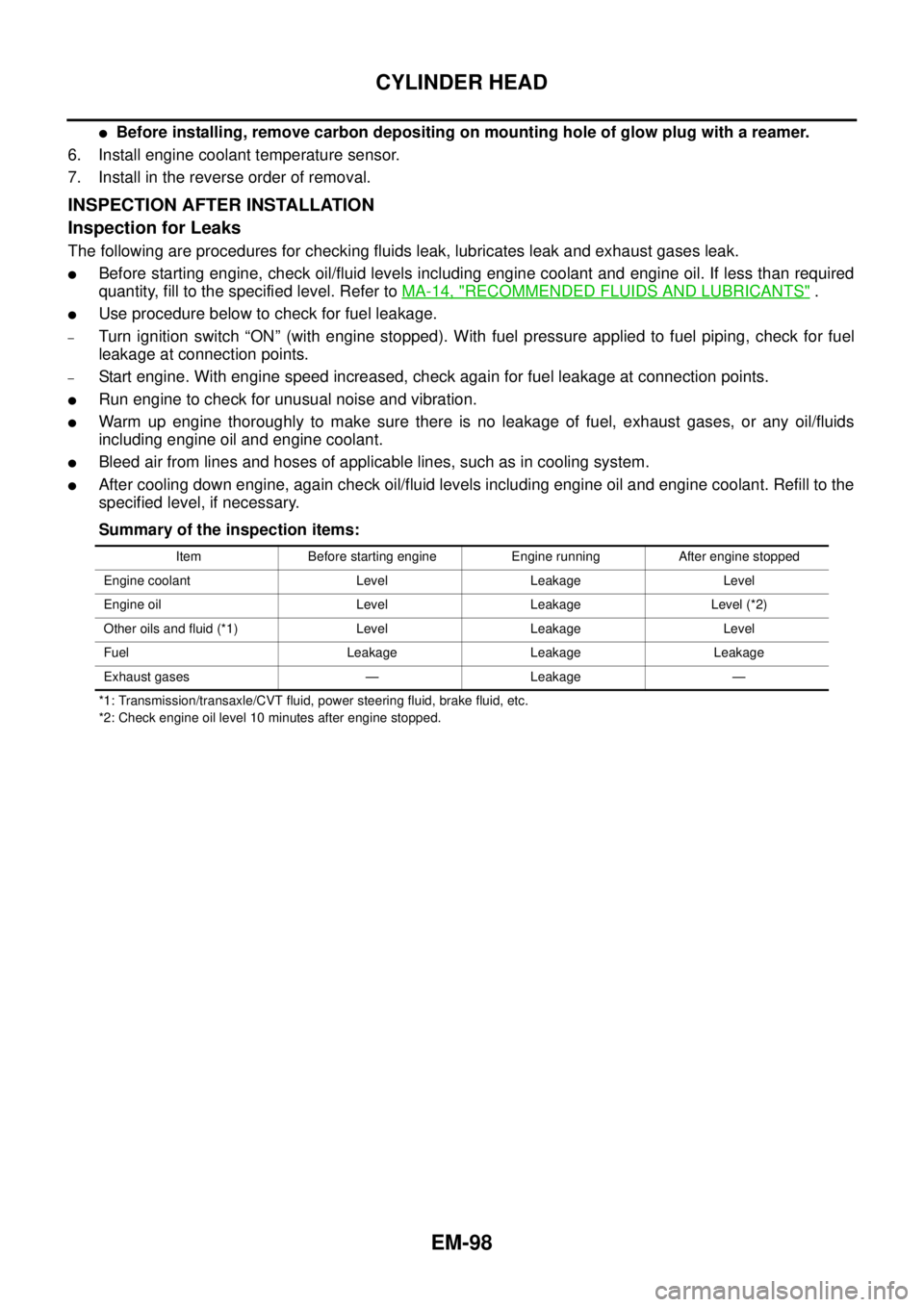
Summary of the inspection items:
*1: Transmission/transaxle/CVT fluid, power steering fluid, brake fluid, etc.
*2: Check engine oil level 10 minutes after engine stopped.Item Before starting engine Engine running After engine stopped
Engine coolant Level Leakage Level
Engine oil Level Leakage Level (*2)
Other oils and fluid (*1) Level Leakage Level
Fuel Leakage Leakage Leakage
Exhaust gases — Leakage —
Page 1537 of 3171
WHEEL HUB
FAX-5
C
E
F
G
H
I
J
K
L
MA
B
FA X
WHEEL HUBPFP:43202
On-Vehicle Inspection and ServiceEDS003I7
Make sure the mounting conditions (looseness, backlash) of each component and component status (wear,
damage) are normal.
WHEEL BEARING INSPECTION
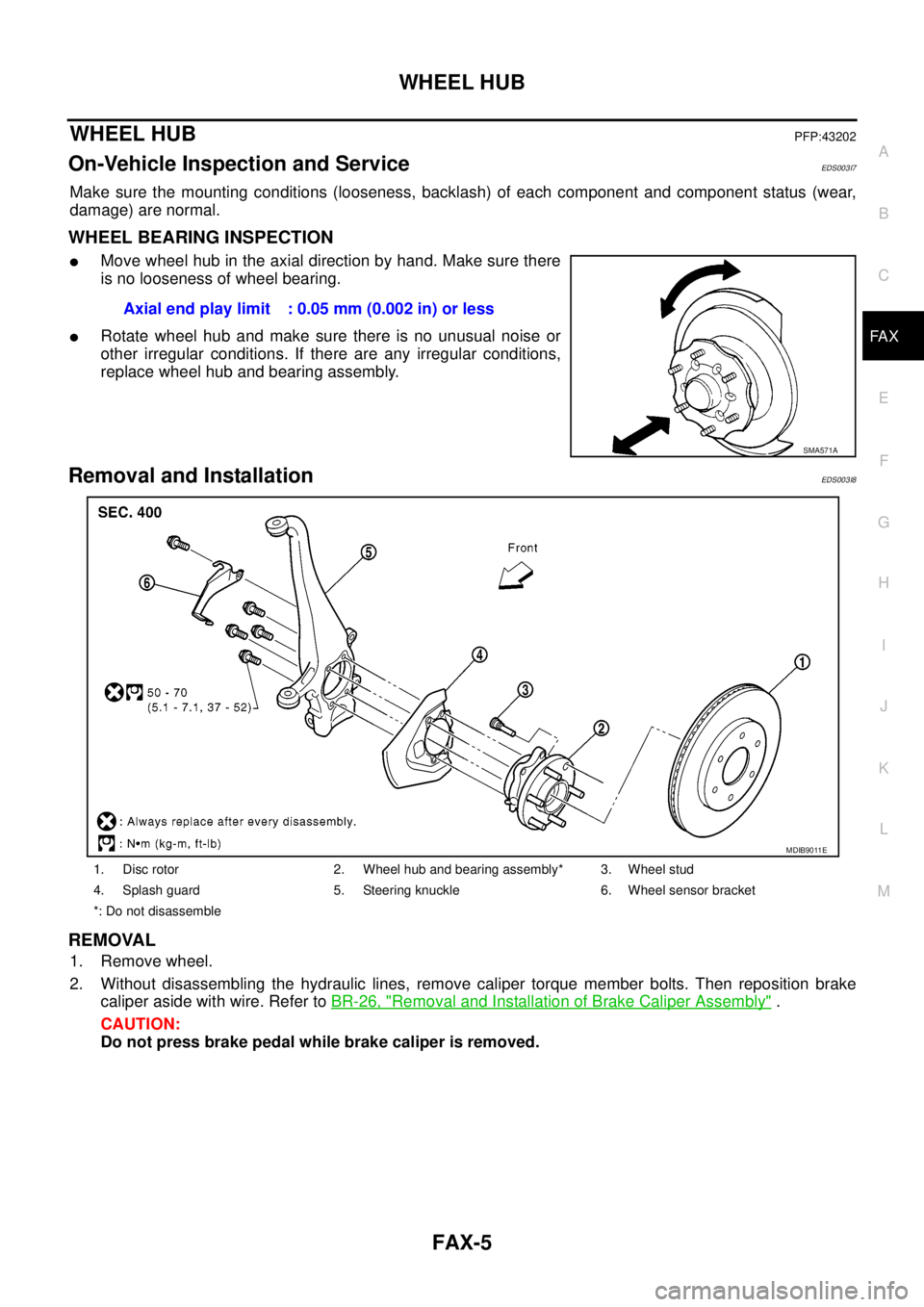
lMove wheel hub in the axial direction by hand. Make sure there
is no looseness of wheel bearing.
lRotate wheel hub and make sure there is no unusual noise or
other irregular conditions. If there are any irregular conditions,
replace wheel hub and bearing assembly.
Removal and InstallationEDS003I8
REMOVAL
1. Remove wheel.
2. Without disassembling the hydraulic lines, remove caliper torque member bolts. Then reposition brake
caliper aside with wire. Refer toBR-26, "
Removal and Installation of Brake Caliper Assembly".
CAUTION:
Do not press brake pedal while brake caliper is removed.Axial end play limit : 0.05 mm (0.002 in) or less
SMA571A
1. Disc rotor 2. Wheel hub and bearing assembly* 3. Wheel stud
4. Splash guard 5. Steering knuckle 6. Wheel sensor bracket
*: Do not disassemble
MDIB9011E
Page 1538 of 3171
FAX-6
WHEEL HUB
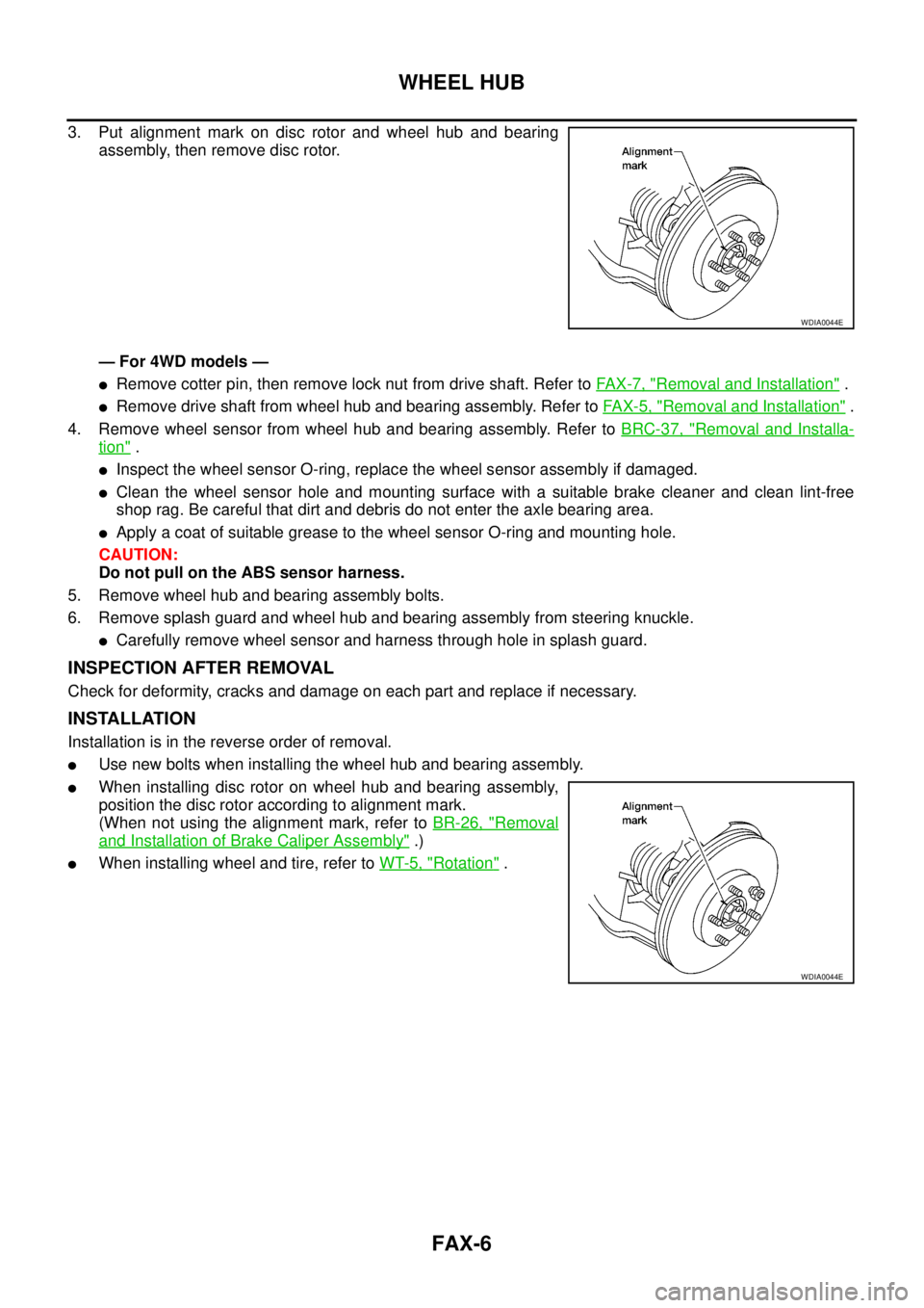
3. Put alignment mark on disc rotor and wheel hub and bearing
assembly, then remove disc rotor.
— For 4WD models —
lRemove cotter pin, then remove lock nut from drive shaft. Refer toFA X - 7 , "Removal and Installation".
lRemove drive shaft from wheel hub and bearing assembly. Refer toFAX-5, "Removal and Installation".
4. Remove wheel sensor from wheel hub and bearing assembly. Refer toBRC-37, "
Removal and Installa-
tion".
lInspect the wheel sensor O-ring, replace the wheel sensor assembly if damaged.
lClean the wheel sensor hole and mounting surface with a suitable brake cleaner and clean lint-free
shop rag. Be careful that dirt and debris do not enter the axle bearing area.
lApply a coat of suitable grease to the wheel sensor O-ring and mounting hole.
CAUTION:
Do not pull on the ABS sensor harness.
5. Remove wheel hub and bearing assembly bolts.
6. Remove splash guard and wheel hub and bearing assembly from steering knuckle.
lCarefully remove wheel sensor and harness through hole in splash guard.
INSPECTION AFTER REMOVAL
Check for deformity, cracks and damage on each part and replace if necessary.
INSTALLATION
Installation is in the reverse order of removal.
lUse new bolts when installing the wheel hub and bearing assembly.
lWhen installing disc rotor on wheel hub and bearing assembly,
position the disc rotor according to alignment mark.
(When not using the alignment mark, refer toBR-26, "
Removal
and Installation of Brake Caliper Assembly".)
lWhen installing wheel and tire, refer toWT-5, "Rotation".
WDIA0044E
WDIA0044E
Page 1539 of 3171
DRIVE SHAFT
FAX-7
C
E
F
G
H
I
J
K
L
MA
B
FA X
DRIVE SHAFTPFP:39100
Removal and InstallationEDS003I9
REMOVAL
1. Remove wheel.
2. Remove ABS sensor harness from mount on knuckle, then disconnect ABS sensor harness connector.
CAUTION:
Do not pull on ABS sensor harness.
3. Remove steering knuckle. Refer toFSU-16, "
Removal and Installation".
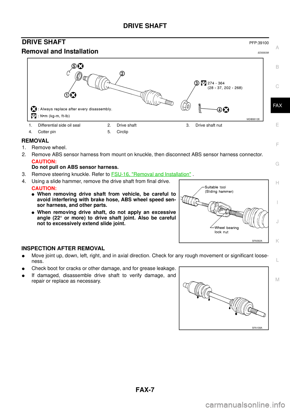
4. Using a slide hammer, remove the drive shaft from final drive.
CAUTION:
lWhen removing drive shaft from vehicle, be careful to
avoid interfering with brake hose, ABS wheel speed sen-
sor harness, and other parts.
lWhen removing drive shaft, do not apply an excessive
angle (22°or more) to drive shaft joint. Also be careful
not to excessively extend slide joint.
INSPECTION AFTER REMOVAL
lMove joint up, down, left, right, and in axial direction. Check for any rough movement or significant loose-
ness.
lCheck boot for cracks or other damage, and for grease leakage.
lIf damaged, disassemble drive shaft to verify damage, and
repair or replace as necessary.
1. Differential side oil seal 2. Drive shaft 3. Drive shaft nut
4. Cotter pin 5. Circlip
MDIB9012E
SFA092A
SFA108A
Page 1555 of 3171
FRONT OIL SEAL
FFD-9
C
E
F
G
H
I
J
K
L
MA
B
FFD
FRONT OIL SEALPFP:38189
Removal and InstallationEDS00353
CAUTION:
Verify identification stamp of replacement frequency put in the lower part of gear carrier to determine
replacement for collapsible spacer when replacing front oil seal. Refer toFFD-9, "
IDENTIFICATION
STAMP OF REPLACEMENT FREQUENCY OF FRONT OIL SEAL". If necessary collapsible spacer
replacement, remove final drive assembly and disassemble it to replace front oil seal and collapsible
spacer. Refer toFFD-15, "
Removal and Installation"andFFD-17, "Disassembly and Assembly".
NOTE:
The reuse of collapsible spacer is prohibited in principle. However, it is reusable on a one-time basis
only in cases when replacing front oil seal.
IDENTIFICATION STAMP OF REPLACEMENT FREQUENCY OF FRONT OIL SEAL
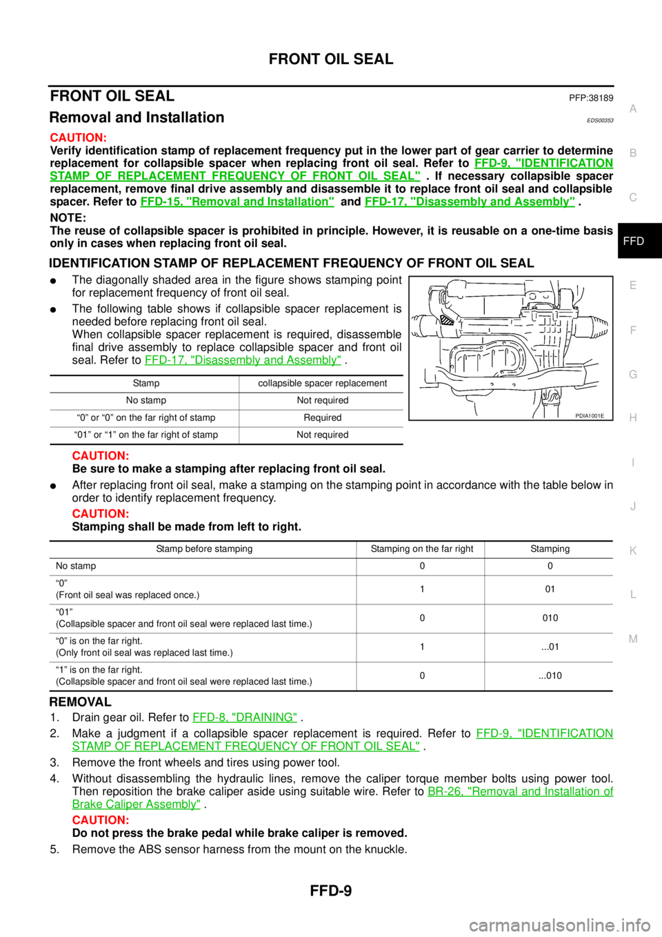
lThe diagonally shaded area in the figure shows stamping point
for replacement frequency of front oil seal.
lThe following table shows if collapsible spacer replacement is
needed before replacing front oil seal.
When collapsible spacer replacement is required, disassemble
final drive assembly to replace collapsible spacer and front oil
seal. Refer toFFD-17, "
Disassembly and Assembly".
CAUTION:
Be sure to make a stamping after replacing front oil seal.
lAfter replacing front oil seal, make a stamping on the stamping point in accordance with the table below in
order to identify replacement frequency.
CAUTION:
Stamping shall be made from left to right.
REMOVAL
1. Drain gear oil. Refer toFFD-8, "DRAINING".
2. Make a judgment if a collapsible spacer replacement is required. Refer toFFD-9, "
IDENTIFICATION
STAMP OF REPLACEMENT FREQUENCY OF FRONT OIL SEAL".
3. Remove the front wheels and tires using power tool.
4. Without disassembling the hydraulic lines, remove the caliper torque member bolts using power tool.
Then reposition the brake caliper aside using suitable wire. Refer toBR-26, "
Removal and Installation of
Brake Caliper Assembly".
CAUTION:
Do not press the brake pedal while brake caliper is removed.
5. Remove the ABS sensor harness from the mount on the knuckle.
Stamp collapsible spacer replacement
No stamp Not required
“0” or “0” on the far right of stamp Required
“01” or “1” on the far right of stamp Not required
PDIA1001E
Stamp before stamping Stamping on the far right Stamping
No stamp00
“0”
(Front oil seal was replaced once.)101
“01”
(Collapsible spacer and front oil seal were replaced last time.)0010
“0”isonthefarright.
(Only front oil seal was replaced last time.)1 ...01
“1”isonthefarright.
(Collapsible spacer and front oil seal were replaced last time.)0 ...010
Page 1556 of 3171
FFD-10
FRONT OIL SEAL
CAUTION:
Do not pull on the ABS sensor harness.
6. Support the lower link using a suitable jack.
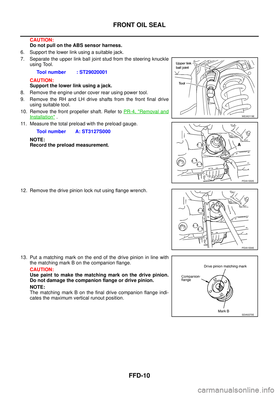
7. Separate the upper link ball joint stud from the steering knuckle
using Tool.
CAUTION:
Support the lower link using a jack.
8. Remove the engine under cover rear using power tool.
9. Remove the RH and LH drive shafts from the front final drive
using suitable tool.
10. Remove the front propeller shaft. Refer toPR-4, "
Removal and
Installation".
11. Measure the total preload with the preload gauge.
NOTE:
Record the preload measurement.
12. Remove the drive pinion lock nut using flange wrench.
13. Put a matching mark on the end of the drive pinion in line with
the matching mark B on the companion flange.
CAUTION:
Use paint to make the matching mark on the drive pinion.
Do not damage the companion flange or drive pinion.
NOTE:
The matching mark B on the final drive companion flange indi-
cates the maximum vertical runout position.Tool number : ST29020001
Tool number A: ST3127S000WEIA0119E
PDIA1002E
PDIA1004E
SDIA0270E
Page 1558 of 3171
FFD-12
FRONT OIL SEAL
3. Apply anti-corrosion oil to the thread and seat of new drive pin-
ion lock nut, and temporarily tighten drive pinion lock nut to drive
pinion.
CAUTION:
Do not reuse drive pinion lock nut.
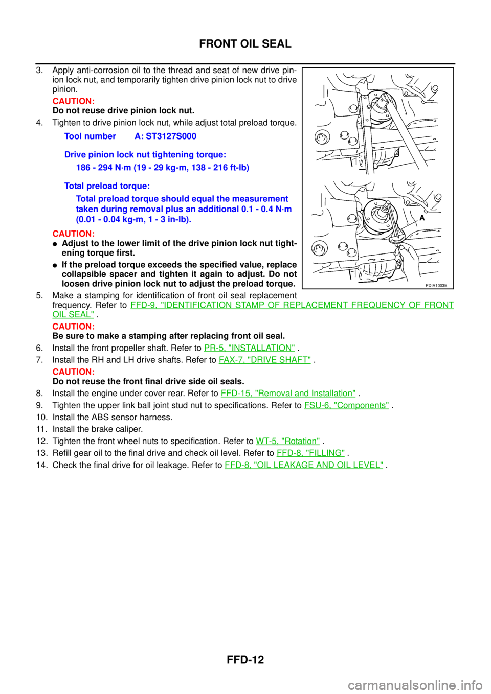
4. Tighten to drive pinion lock nut, while adjust total preload torque.
CAUTION:
lAdjust to the lower limit of the drive pinion lock nut tight-
ening torque first.
lIf the preload torque exceeds the specified value, replace
collapsible spacer and tighten it again to adjust. Do not
loosen drive pinion lock nut to adjust the preload torque.
5. Make a stamping for identification of front oil seal replacement
frequency. Refer toFFD-9, "
IDENTIFICATION STAMP OF REPLACEMENT FREQUENCY OF FRONT
OIL SEAL".
CAUTION:
Be sure to make a stamping after replacing front oil seal.
6. Install the front propeller shaft. Refer toPR-5, "
INSTALLATION".
7. Install the RH and LH drive shafts. Refer toFA X - 7 , "
DRIVE SHAFT".
CAUTION:
Do not reuse the front final drive side oil seals.
8. Install the engine under cover rear. Refer toFFD-15, "
Removal and Installation".
9. Tighten the upper link ball joint stud nut to specifications. Refer toFSU-6, "
Components".
10. Install the ABS sensor harness.
11. Install the brake caliper.
12. Tighten the front wheel nuts to specification. Refer toWT-5, "
Rotation".
13. Refill gear oil to the final drive and check oil level. Refer toFFD-8, "
FILLING".
14. Check the final drive for oil leakage. Refer toFFD-8, "
OIL LEAKAGE AND OIL LEVEL". Tool number A: ST3127S000
Drive pinion lock nut tightening torque:
186 - 294 N·m (19 - 29 kg-m, 138 - 216 ft-lb)
Total preload torque:
Total preload torque should equal the measurement
taken during removal plus an additional 0.1 - 0.4 N·m
(0.01 - 0.04 kg-m, 1 - 3 in-lb).
PDIA1003E
Page 1559 of 3171
SIDE OIL SEAL
FFD-13
C
E
F
G
H
I
J
K
L
MA
B
FFD
SIDE OIL SEALPFP:33142
Removal and InstallationEDS00354
REMOVAL
1. Remove the front wheels and tires using power tool.
2. Without disassembling the hydraulic lines, remove the caliper torque member bolts using power tool.
Then reposition the brake caliper aside using suitable wire. Refer toBR-26, "
Removal and Installation of
Brake Caliper Assembly".
CAUTION:
Do not press the brake pedal while brake caliper is removed.
3. Remove the ABS sensor harness from the mount on the knuckle.
CAUTION:
Do not pull on the ABS sensor harness.
4. Support the lower link using a suitable jack.
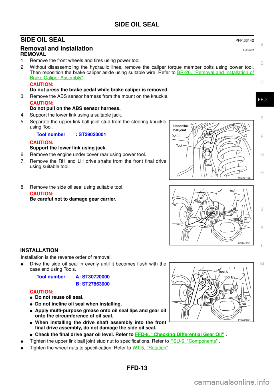
5. Separate the upper link ball joint stud from the steering knuckle
using Tool.
CAUTION:
Support the lower link using jack.
6. Remove the engine under cover rear using power tool.
7. Remove the RH and LH drive shafts from the front final drive
using suitable tool.
8. Remove the side oil seal using suitable tool.
CAUTION:
Be careful not to damage gear carrier.
INSTALLATION
Installation is the reverse order of removal.
lDrive the side oil seal in evenly until it becomes flush with the
case end using Tools.
CAUTION:
lDo not reuse oil seal.
lDo not incline oil seal when installing.
lApply multi-purpose grease onto oil seal lips and gear oil
onto the circumference of oil seal.
lWhen installing the drive shaft assembly into the front
final drive assembly, do not damage the side oil seal.
lCheck the final drive gear oil level. Refer toFFD-8, "Checking Differential Gear Oil".
lTighten the upper link ball joint stud nut to specifications. Refer toFSU-6, "Components".
lTighten the wheel nuts to specification. Refer toWT-5, "Rotation". Tool number : ST29020001
WEIA0119E
LDIA0173E
Tool number A: ST30720000
B: ST27863000
PDIA0826E