2005 NISSAN NAVARA sensor
[x] Cancel search: sensorPage 1770 of 3171

INSTRUMENT PANEL ASSEMBLY
IP-11
C
D
E
F
G
H
J
K
L
MA
B
IP
1. Remove the center console. Refer toIP-16, "CENTER CONSOLE".
2. Remove the steering column covers. Refer toPS-11, "
STEERING COLUMN".
3. Remove the combination meter. Refer toIP-13, "
COMBINATION METER".
4. Release then disconnect the optical sensor harness.
5. Remove the LH and RH front pillar upper garnish.
6. Remove cluster lid C.
7. Remove screws fixing CD Audio bracket, then remove CD Audio unit assembly. (If equipped). Refer toAV-
73, "Auido Unit (1CD Player Type)".
8. Remove cluster lid D. Refer toIP-12, "
CLUSTER LID D".
9. Remove screws fixing GPS Antenna, then move GPS Antenna.
10. Remove screws fixing display unit bracket, then remove display unit assembly. (If equipped)
11. Remove front passenger air bag module.
12. Remove instrument panel.
lDisconnect harnesses to instrument panel speakers LH and RH and remove speakers.
lDisconnect all remaining harnesses.
lRemove the passenger air bag module. Refer toSRS-40, "FRONT PASSENGER AIR BAG MODULE".
Installation
Installation is in the reverse order of removal.
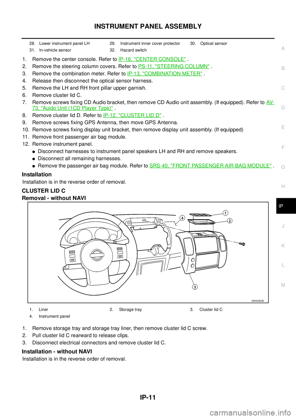
CLUSTER LID C
Removal - without NAVI
1. Remove storage tray and storage tray liner, then remove cluster lid C screw.
2. Pull cluster lid C rearward to release clips.
3. Disconnect electrical connectors and remove cluster lid C.
Installation - without NAVI
Installation is in the reverse order of removal.
28. Lower instrument panel LH 29. Instrument inner cover protector 30. Optical sensor
31. In-vehicle sensor 32. Hazard switch
WIIA0563E
1. Liner 2. Storage tray 3. Cluster lid C
4. Instrument panel
Page 1782 of 3171
![NISSAN NAVARA 2005 Repair Workshop Manual TROUBLE DIAGNOSES WORK FLOW
LAN-5
[CAN]
C
D
E
F
G
H
I
J
L
MA
B
LAN
TROUBLE DIAGNOSES WORK FLOWPFP:00004
When Displaying CAN Communication System ErrorsEKS00LBH
WHEN A MALFUNCTION IS DETECTED BY CAN CO NISSAN NAVARA 2005 Repair Workshop Manual TROUBLE DIAGNOSES WORK FLOW
LAN-5
[CAN]
C
D
E
F
G
H
I
J
L
MA
B
LAN
TROUBLE DIAGNOSES WORK FLOWPFP:00004
When Displaying CAN Communication System ErrorsEKS00LBH
WHEN A MALFUNCTION IS DETECTED BY CAN CO](/manual-img/5/57362/w960_57362-1781.png)
TROUBLE DIAGNOSES WORK FLOW
LAN-5
[CAN]
C
D
E
F
G
H
I
J
L
MA
B
LAN
TROUBLE DIAGNOSES WORK FLOWPFP:00004
When Displaying CAN Communication System ErrorsEKS00LBH
WHEN A MALFUNCTION IS DETECTED BY CAN COMMUNICATION SYSTEM
lCAN communication line is open. (CAN H, CAN L, or both)
lCAN communication line is shorted. (Ground, between CAN lines, or other harnesses)
lThe areas related to CAN communication of unit is malfunctioning.
WHEN A MALFUNCTION IS DETECTED EXCEPT CAN COMMUNICATION SYSTEM
lRemoval and installation of parts : When the units that perform CAN communication or the sensors
related to CAN communication are removed and installed, malfunction may be detected (or DTC other
than CAN communication may be detected).
lFuse blown out (removed): CAN communication of the unit may be stopped at such time.
lLow voltage : If the voltage decreases because of battery discharge when IGN is ON, malfunction may be
detected by self-diagnosis according to the units.
Page 1812 of 3171
![NISSAN NAVARA 2005 Repair Workshop Manual CAN COMMUNICATION
LAN-35
[CAN]
C
D
E
F
G
H
I
J
L
MA
B
LAN
Closed throttle position signal T R
Cooling fan speed request signal TR
Engine coolant temperature signal T R R
Engine speed signal T R R R
En NISSAN NAVARA 2005 Repair Workshop Manual CAN COMMUNICATION
LAN-35
[CAN]
C
D
E
F
G
H
I
J
L
MA
B
LAN
Closed throttle position signal T R
Cooling fan speed request signal TR
Engine coolant temperature signal T R R
Engine speed signal T R R R
En](/manual-img/5/57362/w960_57362-1811.png)
CAN COMMUNICATION
LAN-35
[CAN]
C
D
E
F
G
H
I
J
L
MA
B
LAN
Closed throttle position signal T R
Cooling fan speed request signal TR
Engine coolant temperature signal T R R
Engine speed signal T R R R
Engine status signal T R R
Fuel consumption monitor signalTR
RT
Glow indicator signal T R
Glow relay signal T R
Malfunction indicator signal T R
Wide open throttle position signal T R
A/T fluid temperature sensor signal T R
A/T position indicator lamp signal T R
OD OFF indicator lamp signal T R
Output shaft revolution signal R T
Turbine revolution signal R T
A/C switch/indicator signal T R
PTC heater signal R T
A/C switch signal R R T
Buzzer output signal T R
Day time running light request signal R T R R
Door switch signalTR R
Front fog light request signal R T R R
Front wiper request signal T R
High beam request signal T R R
Horn chirp signalTR
Low beam request signal T R
Position light request signal T R R
Rear fog light request signal R T R
Rear window defogger switch signal R T R
Sleep wake up signal T R R
Theft warning horn request signal T R
Trailer lamp signalTR
Turn indicator signal T R
1st position switch signal R T
Distance to empty signal R T
Fuel level low warning signal R T
Overdrive control switch signal R T
Stop lamp switch signal R T
ABS operation signal R T
ABS warning lamp signalRT Signals ECM TCMNAVI
control
unitFront air
controlBCMCombi-
nation
meterABS
actuator
and elec-
tric unit
(control
unit)IPDM
E/R
Page 1819 of 3171
![NISSAN NAVARA 2005 Repair Workshop Manual LAN-42
[CAN]
CAN COMMUNICATION
Engine coolant temperature signal T R R
Engine speed signal T R R R R
Engine status signal T R R
Fuel consumption monitor signalTR
RT
Glow indicator signal T R
Glow rela NISSAN NAVARA 2005 Repair Workshop Manual LAN-42
[CAN]
CAN COMMUNICATION
Engine coolant temperature signal T R R
Engine speed signal T R R R R
Engine status signal T R R
Fuel consumption monitor signalTR
RT
Glow indicator signal T R
Glow rela](/manual-img/5/57362/w960_57362-1818.png)
LAN-42
[CAN]
CAN COMMUNICATION
Engine coolant temperature signal T R R
Engine speed signal T R R R R
Engine status signal T R R
Fuel consumption monitor signalTR
RT
Glow indicator signal T R
Glow relay signal T R
Malfunction indicator signal T R
Wide open throttle position signal T R
A/T fluid temperature sensor signal T R
A/T position indicator lamp signal T R R
OD OFF indicator lamp signal T R
Output shaft revolution signal R T R
Turbine revolution signal R T
A/C switch/indicator signal T R
Differential lock indicator signal T R
Differential lock switch signal T R
PTC heater signal
*RT
A/C switch signal R R T
Buzzer output signal T R
Day time running light request signal R T R R
Door switch signal T R R
Front fog light request signal R T R R
Front wiper request signal T R
High beam request signal T R R
Horn chirp signalTR
Low beam request signal T R
Position light request signal T R R
Rear fog light request signal R T R
Rear window defogger switch signal R T R
Sleepwakeupsignal T R R
Theft warning horn request signal T R
Trailer lamp signal T R
Turn indicator signal T R
1st position switch signal R T
Distance to empty signal R T
Fuel level low warning signal R T
Overdrive control switch signal R T
Stop lamp switch signal R TSignals ECM TCMNAVI
con-
trol
unitDiffer-
ential
lock
con-
trol
unitFront
air
controlBCMCom-
bina-
tion
meterTrans-
fer
con-
trol
unitABS
actua-
tor and
elec-
tric unit
(con-
trol
unit)IPDM
E/R
Page 2085 of 3171

LT-2
AUTO LIGHT SYSTEM ............................................. 49
Component Parts and Harness Connector Location... 49
System Description ................................................. 49
OUTLINE ............................................................. 49
COMBINATION SWITCH READING FUNCTION... 50
CAN Communication System Description .............. 50
Major Components and Functions .......................... 50
Schematic ............................................................... 51
Wiring Diagram — AUTO/L — ................................ 52
Terminals and Reference Values for BCM .............. 56
Terminals and Reference Values for IPDM E/R ...... 57
How to Proceed With Trouble Diagnosis ................ 57
Preliminary Check .................................................. 58
SETTING CHANGE FUNCTIONS ....................... 58
CHECK POWER SUPPLY AND GROUND CIR-
CUIT .................................................................... 58
CONSULT-II Function (BCM) .................................. 59
CONSULT-II OPERATION ................................... 59
WORK SUPPORT ............................................... 60
DATA MONITOR .................................................. 60
ACTIVE TEST ..................................................... 61
Trouble Diagnosis Chart by Symptom .................... 62
Lighting Switch Inspection ...................................... 62
Light and Rain Sensor System Inspection .............. 63
Removal and Installation of Light and Rain Sensor... 65
REMOVAL ........................................................... 65
INSTALLATION .................................................... 65
HEADLAMP AIMING CONTROL (MANUAL) ........... 66
Schematic ............................................................... 66
Wiring Diagram — H/AIM — ................................... 67
Removal and Installation ........................................ 70
Switch Circuit Inspection ........................................ 70
FRONT FOG LAMP .................................................. 71
Component Parts and Harness Connector Location... 71
System Description ................................................. 71
OUTLINE ............................................................. 71
COMBINATION SWITCH READING FUNCTION... 72
CAN Communication System Description .............. 72
Schematic ............................................................... 73
Wiring Diagram — F/FOG — .................................. 74
Terminals and Reference Values for BCM .............. 77
Terminals and Reference Values for IPDM E/R ...... 77
How to Proceed With Trouble Diagnosis ................ 78
Preliminary Check .................................................. 78
CHECK POWER SUPPLY AND GROUND CIR-
CUIT .................................................................... 78
CONSULT-II Functions (BCM) ................................ 79
CONSULT-II Functions (IPDM E/R) ........................ 79
Front Fog Lamps Do Not Illuminate (Both Sides) ... 80
Front Fog Lamp Does Not Illuminate (One Side) ... 82
Front Fog Lamp Indicator Lamp Does Not Illuminate... 83
Front Fog Lamps Do Not Turn OFF ........................ 84
Aiming Adjustment .................................................. 85
Bulb Replacement .................................................. 86
Removal and Installation of Front Fog Lamp .......... 86
REMOVAL ........................................................... 86
INSTALLATION .................................................... 86
REAR FOG LAMP ..................................................... 87
Component Parts and Harness Connector Location... 87System Description ................................................. 87
OUTLINE ............................................................. 87
COMBINATION SWITCH READING FUNCTION... 88
CAN Communication System Description .............. 88
CAN Communication Unit ....................................... 88
Wiring Diagram — R/FOG — .................................. 89
Terminals and Reference Values for BCM .............. 91
How to Proceed With Trouble Diagnosis ................ 91
Preliminary Check ................................................... 92
CHECK POWER SUPPLY AND GROUND CIR-
CUIT ..................................................................... 92
CONSULT-II Functions (BCM) ................................ 93
Rear Fog Lamp Does Not Operate ......................... 93
Rear Fog Lamp Indicator Lamp Does Not Illuminate... 95
Rear Fog Lamp Does Not Turn OFF ....................... 96
Bulb Replacement ................................................... 96
Removal and Installation ......................................... 96
TURN SIGNAL AND HAZARD WARNING LAMPS... 97
Component Parts and Harness Connector Location... 97
System Description ................................................. 97
OUTLINE ............................................................. 97
TURN SIGNAL OPERATION ............................... 97
HAZARD LAMP OPERATION ............................. 98
REMOTE KEYLESS ENTRY SYSTEM OPERA-
TION .................................................................... 99
COMBINATION SWITCH READING FUNCTION... 99
CAN Communication System Description .............. 99
Wiring Diagram — TURN — .................................100
Terminals and Reference Values for BCM ............102
How to Proceed With Trouble Diagnosis ..............103
Preliminary Check .................................................103
CHECK POWER SUPPLY AND GROUND CIR-
CUIT ...................................................................103
CONSULT-II Function (BCM) ................................105
CONSULT-II OPERATION .................................105
DATA MONITOR ................................................106
ACTIVE TEST ....................................................106
Turn Signal Lamp Does Not Operate ....................107
Hazard Warning Lamp Does Not Operate But Turn
Signal Lamps Operate ..........................................109
Turn Signal Indicator Lamp Does Not Operate .....110
Bulb Replacement (Front Turn Signal Lamp) ........ 111
Bulb Replacement (Rear Turn Signal Lamp) ........ 111
Bulb Replacement (Side Turn Signal Lamp) ......... 111
Removal and Installation of Front Turn Signal Lamp. 111
Removal and Installation of Rear Turn Signal Lamp. 111
Removal and Installation of Side Turn Signal Lamp. 111
REMOVAL .......................................................... 111
INSTALLATION .................................................. 111
LIGHTING AND TURN SIGNAL SWITCH ..............112
Removal and Installation .......................................112
REMOVAL ..........................................................112
INSTALLATION ..................................................112
HAZARD SWITCH ...................................................113
Removal and Installation .......................................113
REMOVAL ..........................................................113
INSTALLATION ..................................................113
COMBINATION SWITCH ........................................114
Wiring Diagram — COMBSW — ..........................114
Page 2132 of 3171

AUTO LIGHT SYSTEM
LT-49
C
D
E
F
G
H
I
J
L
MA
B
LT
AUTO LIGHT SYSTEMPFP:28491
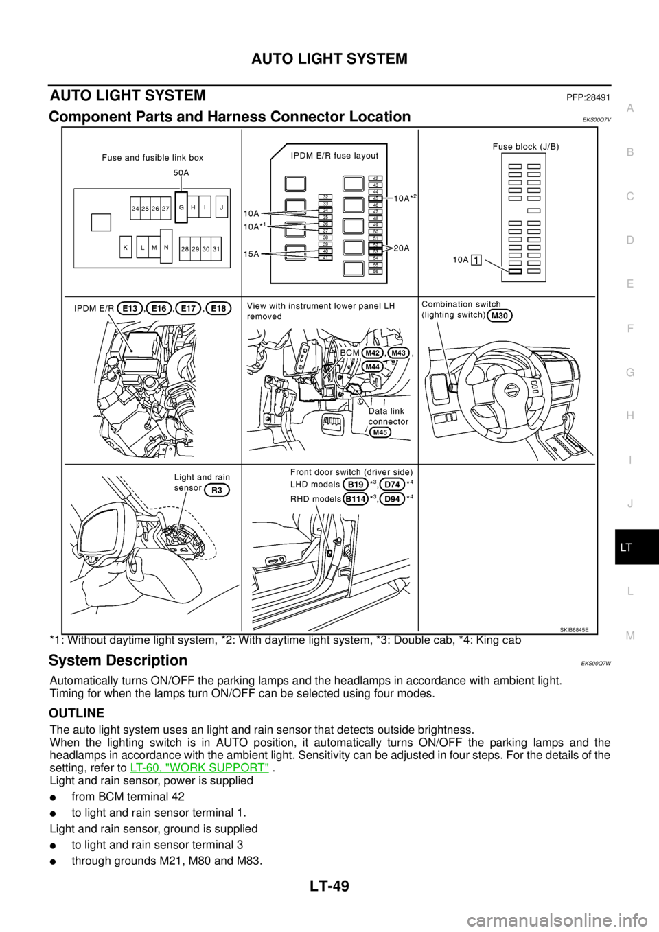
Component Parts and Harness Connector LocationEKS00Q7V
*1: Without daytime light system, *2: With daytime light system, *3: Double cab, *4: King cab
System DescriptionEKS00Q7W
Automatically turns ON/OFF the parking lamps and the headlamps in accordance with ambient light.
Timing for when the lamps turn ON/OFF can be selected using four modes.
OUTLINE
The auto light system uses an light and rain sensor that detects outside brightness.
When the lighting switch is in AUTO position, it automatically turns ON/OFF the parking lamps and the
headlamps in accordance with the ambient light. Sensitivity can be adjusted in four steps. For the details of the
setting, refer toLT-60, "
WORK SUPPORT".
Light and rain sensor, power is supplied
lfrom BCM terminal 42
lto light and rain sensor terminal 1.
Light and rain sensor, ground is supplied
lto light and rain sensor terminal 3
lthrough grounds M21, M80 and M83.
SKIB6845E
Page 2133 of 3171

LT-50
AUTO LIGHT SYSTEM
When ignition switch is turned to ON position and when outside brightness is darker than prescribed level,
input is supplied
lto BCM terminal 24
lfrom light and rain sensor terminal 2.
The headlamps will then illuminate. For a description of headlamp operation, refer toLT-49, "
System Descrip-
tion".
COMBINATION SWITCH READING FUNCTION
Refer toBCS-3, "COMBINATION SWITCH READING FUNCTION".
CAN Communication System DescriptionEKS00Q7X
Refer toLAN-23, "CAN COMMUNICATION".
Major Components and FunctionsEKS00Q7Y
Components Functions
BCM
lTurns ON/OFF circuits of tail light and headlamp according to signals from light and rain sensor, lighting switch
(AUTO), driver door switch, passenger door switch, rear door switches, back door switch, glass hatch opener
switch and ignition switch (ON, OFF).
Light and rain
sensor
lConverts outside brightness (lux) to voltage, and sends it to BCM. (Detects lightness of 50 to 1,300 lux.)
Page 2139 of 3171

LT-56
AUTO LIGHT SYSTEM
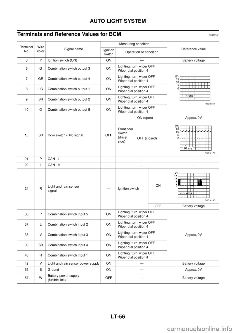
Terminals and Reference Values for BCM
EKS00Q81
Terminal
No.Wire
colorSignal nameMeasuring condition
Reference value
Ignition
switchOperation or condition
3 Y Ignition switch (ON) ON — Battery voltage
6 G Combination switch output 3 ONLighting, turn, wiper OFF
Wiper dial position 4
7 GR Combination switch output 4 ONLighting, turn, wiper OFF
Wiper dial position 4
8 LG Combination switch output 1 ONLighting, turn, wiper OFF
Wiper dial position 4
9 BR Combination switch output 2 ONLighting, turn, wiper OFF
Wiper dial position 4
10 O Combination switch output 5 ONLighting, turn, wiper OFF
Wiper dial position 4
15 SB Door switch (DR) signal OFFFront door
switch
(driver
side)ON (open) Approx. 0V
OFF (closed)
21 P CAN-L—— —
22 L CAN-H—— —
24 RLight and rain sensor
signal— Ignition switchON
OFF Battery voltage
36 P Combination switch input 5 ONLighting, turn, wiper OFF
Wiper dial position 4
Approx. 0V 37 L Combination switch input 2 ONLighting, turn, wiper OFF
Wiper dial position 4
38 V Combination switch input 3 ONLighting, turn, wiper OFF
Wiper dial position 4
39 SB Combination switch input 4 ONLighting, turn, wiper OFF
Wiper dial position 4
40 R Combination switch input 1 ONLighting, turn, wiper OFF
Wiper dial position 4
42 V Light and rain sensor power supply ON — Battery voltage
55 B Ground ON — Approx. 0V
57 WBattery power supply
(fusible link)OFF — Battery voltage
PKIB4958J
PKIC1217E
PKIC1618E