Page 2478 of 3171

TROUBLE DIAGNOSIS
MTC-91
C
D
E
F
G
H
I
K
L
MA
B
MTC
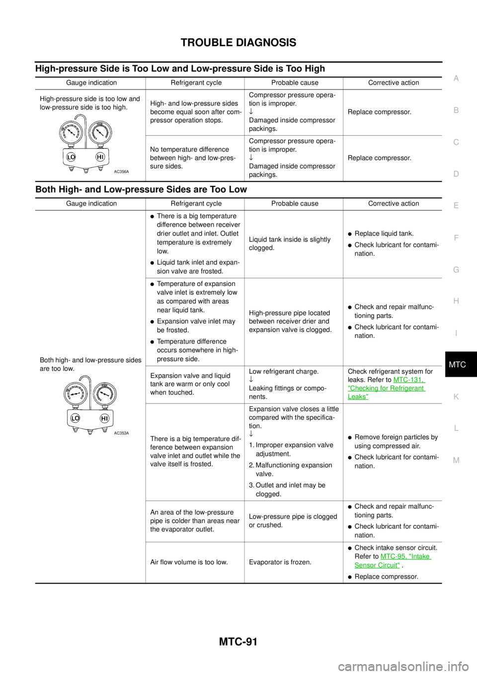
High-pressure Side is Too Low and Low-pressure Side is Too High
Both High- and Low-pressure Sides are Too Low
Gauge indication Refrigerant cycle Probable cause Corrective action
High-pressure side is too low and
low-pressure side is too high.High- and low-pressure sides
become equal soon after com-
pressor operation stops.Compressor pressure opera-
tion is improper.
¯
Damaged inside compressor
packings.Replace compressor.
No temperature difference
between high- and low-pres-
sure sides.Compressor pressure opera-
tion is improper.
¯
Damaged inside compressor
packings.Replace compressor.
AC356A
Gauge indication Refrigerant cycle Probable cause Corrective action
Both high- and low-pressure sides
are too low.
lThere is a big temperature
difference between receiver
drier outlet and inlet. Outlet
temperature is extremely
low.
lLiquid tank inlet and expan-
sion valve are frosted.Liquid tank inside is slightly
clogged.
lReplace liquid tank.
lCheck lubricant for contami-
nation.
lTemperature of expansion
valve inlet is extremely low
as compared with areas
near liquid tank.
lExpansion valve inlet may
be frosted.
lTemperature difference
occurs somewhere in high-
pressure side.High-pressure pipe located
between receiver drier and
expansion valve is clogged.
lCheck and repair malfunc-
tioning parts.
lCheck lubricant for contami-
nation.
Expansion valve and liquid
tank are warm or only cool
when touched.Low refrigerant charge.
¯
Leaking fittings or compo-
nents.Check refrigerant system for
leaks. Refer toMTC-131,
"Checking for Refrigerant
Leaks"
There is a big temperature dif-
ference between expansion
valve inlet and outlet while the
valve itself is frosted.Expansion valve closes a little
compared with the specifica-
tion.
¯
1. Improper expansion valve
adjustment.
2. Malfunctioning expansion
valve.
3. Outlet and inlet may be
clogged.lRemove foreign particles by
using compressed air.
lCheck lubricant for contami-
nation.
An area of the low-pressure
pipe is colder than areas near
the evaporator outlet.Low-pressure pipe is clogged
or crushed.
lCheck and repair malfunc-
tioning parts.
lCheck lubricant for contami-
nation.
Air flow volume is too low. Evaporator is frozen.
lCheck intake sensor circuit.
Refer toMTC-95, "
Intake
Sensor Circuit".
lReplace compressor.
AC353A
Page 2480 of 3171
TROUBLE DIAGNOSIS
MTC-93
C
D
E
F
G
H
I
K
L
MA
B
MTC
Insufficient HeatingEJS005GN
SYMPTOM: Insufficient heating
INSPECTION FLOW
*1 .MTC-53, "Operational Check".*2MTC-63, "Air Mix Door Motor Cir-
cuit".*3MTC-51, "
A/C System Self-diagno-
sis Function".
*4MTC-51, "
A/C System Self-diagno-
sis Function".*5MTC-71, "
Blower Motor Circuit".*6EC-103, "DTC P0117, P0118 ECT
SENSOR".
*7CO-7, "
Changing Engine Coolant".*8CO-13, "Checking Reservoir Tank
Cap".
MJIB0354E
Page 2482 of 3171
TROUBLE DIAGNOSIS
MTC-95
C
D
E
F
G
H
I
K
L
MA
B
MTC
Self-diagnosisEJS005GP
SYMPTOM: Self-diagnosis cannot be performed (Vehicles equipped with NAVI only).
INSPECTION FLOW
Intake Sensor CircuitEJS005GR
COMPONENT DESCRIPTION
Intake Sensor
The intake sensor is located on the heater & cooling unit. It converts
temperature of air after it passes through the evaporator into a resis-
tance value which is then input to the front air control.
NOTE:
This illustration is for LHD models.
The layout for RHD models is symmetrically opposite.
*1MTC-122, "REMOVAL".*2MTC-122, "INSTALLATION".*3MTC-24, "Maintenance of Lubricant
Quantity in Compressor".
*4MTC-53, "
Operational Check".*5EM-12, "DRIVE BELTS".
*1MTC-55, "
Power Supply and Ground
Circuit for Front Air Control".2.MTC-63, "
Air Mix Door Motor Cir-
cuit".3.MTC-53, "
Operational Check".
MJIB0246E
MJIB0198E
Page 2483 of 3171

MTC-96
TROUBLE DIAGNOSIS
DIAGNOSTIC PROCEDURE FOR INTAKE SENSOR
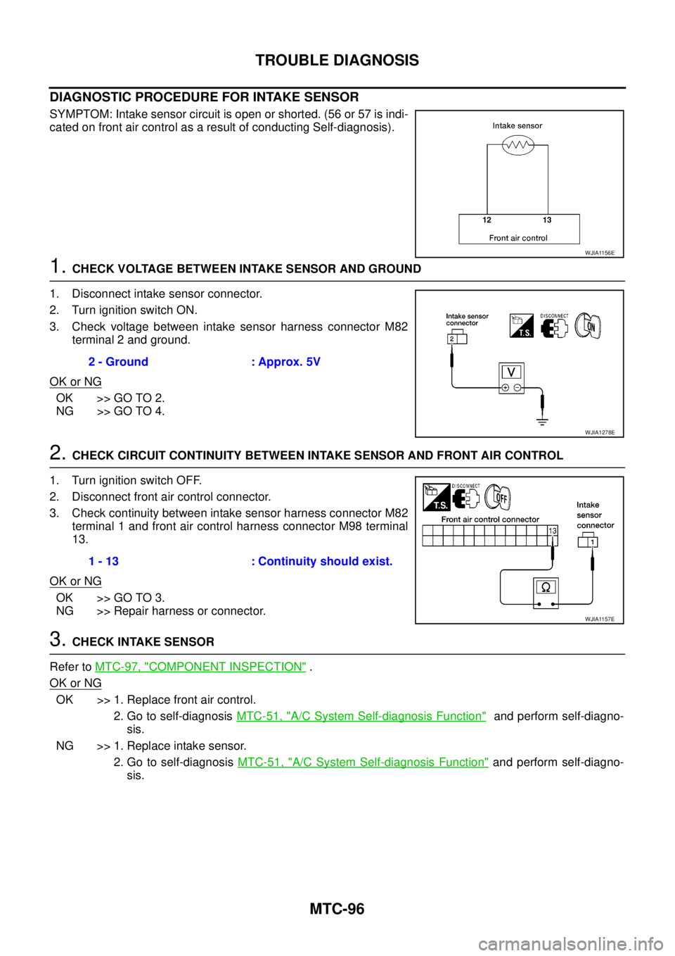
SYMPTOM: Intake sensor circuit is open or shorted. (56 or 57 is indi-
cated on front air control as a result of conducting Self-diagnosis).
1.CHECK VOLTAGE BETWEEN INTAKE SENSOR AND GROUND
1. Disconnect intake sensor connector.
2. Turn ignition switch ON.
3. Check voltage between intake sensor harness connector M82
terminal 2 and ground.
OK or NG
OK >> GO TO 2.
NG >> GO TO 4.
2.CHECK CIRCUIT CONTINUITY BETWEEN INTAKE SENSOR AND FRONT AIR CONTROL
1. Turn ignition switch OFF.
2. Disconnect front air control connector.
3. Check continuity between intake sensor harness connector M82
terminal 1 and front air control harness connector M98 terminal
13.
OK or NG
OK >> GO TO 3.
NG >> Repair harness or connector.
3.CHECK INTAKE SENSOR
Refer toMTC-97, "
COMPONENT INSPECTION".
OK or NG
OK >> 1. Replace front air control.
2. Go to self-diagnosisMTC-51, "
A/C System Self-diagnosis Function"and perform self-diagno-
sis.
NG >> 1. Replace intake sensor.
2. Go to self-diagnosisMTC-51, "
A/C System Self-diagnosis Function"and perform self-diagno-
sis.
WJIA1156E
2 - Ground : Approx. 5V
WJIA1278E
1 - 13 : Continuity should exist.
WJIA1157E
Page 2484 of 3171

TROUBLE DIAGNOSIS
MTC-97
C
D
E
F
G
H
I
K
L
MA
B
MTC
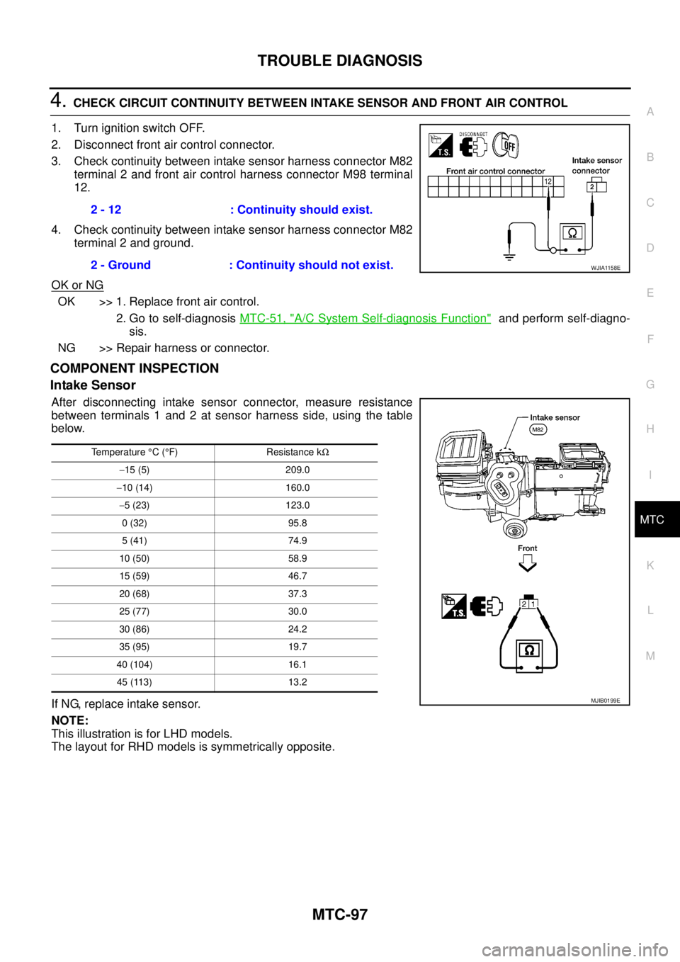
4.CHECK CIRCUIT CONTINUITY BETWEEN INTAKE SENSOR AND FRONT AIR CONTROL
1. Turn ignition switch OFF.
2. Disconnect front air control connector.
3. Check continuity between intake sensor harness connector M82
terminal 2 and front air control harness connector M98 terminal
12.
4. Check continuity between intake sensor harness connector M82
terminal 2 and ground.
OK or NG
OK >> 1. Replace front air control.
2. Go to self-diagnosisMTC-51, "
A/C System Self-diagnosis Function"and perform self-diagno-
sis.
NG >> Repair harness or connector.
COMPONENT INSPECTION
Intake Sensor
After disconnecting intake sensor connector, measure resistance
between terminals 1 and 2 at sensor harness side, using the table
below.
If NG, replace intake sensor.
NOTE:
This illustration is for LHD models.
The layout for RHD models is symmetrically opposite.2 - 12 : Continuity should exist.
2 - Ground : Continuity should not exist.
WJIA1158E
Temperature°C(°F) Resistance kW
-15 (5) 209.0
-10 (14) 160.0
-5 (23) 123.0
0 (32) 95.8
5 (41) 74.9
10 (50) 58.9
15 (59) 46.7
20 (68) 37.3
25 (77) 30.0
30 (86) 24.2
35 (95) 19.7
40 (104) 16.1
45 (113) 13.2
MJIB0199E
Page 2486 of 3171
INTAKE SENSOR
MTC-99
C
D
E
F
G
H
I
K
L
MA
B
MTC
INTAKE SENSORPFP:27723
Removal and InstallationEJS005GT
REMOVAL
1. Remove the instrument panel. Refer toIP-10, "Removal and Installation".
2. Disconnect the intake sensor electrical connector.
NOTE:
The intake sensor is located on the top of the heater and cooling
unit assembly next to the A/C evaporator cover.
3. Twist the intake sensor to remove the intake sensor from the
heater and cooling unit assembly.
INSTALLATION
Installation is in the reverse order of removal.
MJIB0325E
Page 2507 of 3171
MTC-120
REFRIGERANT LINES
Components
EJS005HB
A/C Compressor and Condenser —LHD Models—
MJIB0276E
1. High-pressure service valve 2. Clip 3. High-pressure A/C pipe
4. Refrigerant pressure sensor 5. Condenser 6. Compressor shaft seal
7. High-pressure flexible A/C hose 8. Low-pressure flexible A/C hose 9. Low-pressure service valve
10. Low-pressure A/C pipe 11. Expansion valve 12. A/C drain hose
Page 2508 of 3171
REFRIGERANT LINES
MTC-121
C
D
E
F
G
H
I
K
L
MA
B
MTC
A/C Compressor and Condenser —RHD Models—
MJIB0277E
1. High-pressure service valve 2. Clip 3. High-pressure A/C pipe
4. Refrigerant pressure sensor 5. Condenser 6. Compressor shaft seal
7. High-pressure flexible A/C hose 8. Low-pressure flexible A/C hose 9. Low-pressure service valve
10. Low-pressure A/C pipe 11. Expansion valve 12. A/C drain hose