Page 2755 of 3171
![NISSAN NAVARA 2005 Repair Workshop Manual RFD-52
[WITH ELECTRONIC LOCKING DIFFERENTIAL]
TROUBLE DIAGNOSIS
CAUTION:
If “CAN COMM CIRCUIT [U1000]” is displayed with other DTCs, first perform the trouble diagnosis for CAN communication
line. NISSAN NAVARA 2005 Repair Workshop Manual RFD-52
[WITH ELECTRONIC LOCKING DIFFERENTIAL]
TROUBLE DIAGNOSIS
CAUTION:
If “CAN COMM CIRCUIT [U1000]” is displayed with other DTCs, first perform the trouble diagnosis for CAN communication
line.](/manual-img/5/57362/w960_57362-2754.png)
RFD-52
[WITH ELECTRONIC LOCKING DIFFERENTIAL]
TROUBLE DIAGNOSIS
CAUTION:
If “CAN COMM CIRCUIT [U1000]” is displayed with other DTCs, first perform the trouble diagnosis for CAN communication
line.
How to Erase Self-diagnostic Results
1. Perform applicable inspection of malfunctioning item and then repair or replace.
2. Start engine and select “SELF-DIAG RESULTS” mode for “DIFF LOCK” with CONSULT-II.
3. Touch “ERASE” on CONSULT-II screen to erase DTC memory.
CAUTION:
If memory cannot be erased, perform diagnosis.
POSI SW ON
[P1839]When differential lock position switch is ON, rotation difference
occurs in wheel speed (rear wheel right and left).RFD-60, "Differential Lock Posi-
tion Switch"
RELAY
[P1844]Differential lock control unit detects as irregular by comparing target
value with monitor value.RFD-63, "Differential Lock Sole-
noid Relay",RFD-64, "Differen-
tial Lock Solenoid"
SOL CIRCUIT
[P1847]Malfunction is detected in differential lock control unit internal circuit.RFD-64, "Differential Lock Sole-
noid"
SOL DISCONNECT
[P1848]lDifferential lock solenoid internal circuit or harness is open.
lDifferential lock solenoid relay does not switch to ON position.RFD-64, "
Differential Lock Sole-
noid"
SOL SHORT
[P1849]Differential lock solenoid internal circuit or harness is shorted.RFD-64, "Differential Lock Sole-
noid"
SOL CURRENT
[P1850]Differential lock solenoid relay does not switch to OFF position.RFD-64, "Differential Lock Sole-
noid"
ABS SYSTEM
[C1203]Malfunction related to wheel sensor has been detected by ABS
actuator and electric unit (control unit).RFD-68, "ABS System"
CAN COMM CIRCUIT
[U1000]Malfunction has been detected from CAN communication line.RFD-69, "CAN Communication
Line"
NO DTC IS DETECTED.
FURTHER TESTING MAY
BE REQUIRED.No NG item has been detected. — Items (CONSULT-II screen
terms)Diagnostic item is detected when... Check item
Page 2756 of 3171
![NISSAN NAVARA 2005 Repair Workshop Manual TROUBLE DIAGNOSIS
RFD-53
[WITH ELECTRONIC LOCKING DIFFERENTIAL]
C
E
F
G
H
I
J
K
L
MA
B
RFD
DATA MONITOR MODE
Operation Procedure
1. Perform “CONSULT-II SETTING PROCEDURE”. Refer toRFD-50, "CONSULT NISSAN NAVARA 2005 Repair Workshop Manual TROUBLE DIAGNOSIS
RFD-53
[WITH ELECTRONIC LOCKING DIFFERENTIAL]
C
E
F
G
H
I
J
K
L
MA
B
RFD
DATA MONITOR MODE
Operation Procedure
1. Perform “CONSULT-II SETTING PROCEDURE”. Refer toRFD-50, "CONSULT](/manual-img/5/57362/w960_57362-2755.png)
TROUBLE DIAGNOSIS
RFD-53
[WITH ELECTRONIC LOCKING DIFFERENTIAL]
C
E
F
G
H
I
J
K
L
MA
B
RFD
DATA MONITOR MODE
Operation Procedure
1. Perform “CONSULT-II SETTING PROCEDURE”. Refer toRFD-50, "CONSULT-II SETTING PROCE-
DURE".
2. Touch “DATA MONITOR”.
3. Select from “SELECT MONITOR ITEM”, screen of data monitor mode is displayed.
NOTE:
When malfunction is detected, CONSULT-II performs REAL-TIME DIAGNOSIS.
Also, any malfunction detected while in this mode will be displayed at real time.
Display Item List
´: Standard –: Not applicable
Monitor item (Unit)SELECT MONITOR ITEM
Remarks
ECU INPUT
SIGNALSMAIN
SIGNALSSELECTION
FROM MENU
BATTERY VOLT [V]´´´Power supply voltage for differential lock
control unit.
4WD MODE [2H/4H/4Lo]´´´4WD shift switch signal status via CAN
communication line is displayed.
VHCL S/SEN-R [km/h] or [mph]´–´Wheel speed calculated by rear wheel
sensor right signal is displayed.
VHCL S/SEN-L [km/h] or [mph]´–´Wheel speed calculated by rear wheel
sensor left signal is displayed.
VHCL S/SEN-RL [km/h] or [mph]´´´Average value between wheel speed cal-
culated by rear wheel sensor right signal
and rear wheel sensor left signal is dis-
played.
D-LOCK SW SIG [ON/OFF]´´´Condition of differential lock mode switch
is displayed.
D-LOCK SIG [ON/OFF]´´´Control status of differential lock is dis-
played.
RELAY ON [ON/OFF]´´´Operating condition of differential lock
solenoid relay is displayed (integrated in
differential lock control unit).
RELAY MTR [ON/OFF]´´´Control status of differential lock solenoid
relay is displayed (integrated in differential
lock control unit).
SOL MTR [ON/OFF]´´´Control status of differential lock solenoid
is displayed.
IND MTR [ON/OFF]´´´Control status of DIFF LOCK indicator
lamp is displayed.
D-LOCK POS SW [ON/OFF]´´´Condition of differential lock position switch
is displayed.
Voltage [V] – –´The value measured by the voltage probe
is displayed.
Frequency [Hz] – –´
The value measured by the pulse probe is
displayed. DUTY-HI (high) [%] – –´
DUTY-LOW (low) [%] – –´
PLS WIDTH-HI [msec] – –´
PLS WIDTH-LOW [msec] – –´
Page 2784 of 3171
![NISSAN NAVARA 2005 Repair Workshop Manual REAR FINAL DRIVE ASSEMBLY
RFD-81
[WITH ELECTRONIC LOCKING DIFFERENTIAL]
C
E
F
G
H
I
J
K
L
MA
B
RFD
REAR FINAL DRIVE ASSEMBLYPFP:38300
Removal and InstallationEDS003BF
REMOVAL
1. Remove the rear propel NISSAN NAVARA 2005 Repair Workshop Manual REAR FINAL DRIVE ASSEMBLY
RFD-81
[WITH ELECTRONIC LOCKING DIFFERENTIAL]
C
E
F
G
H
I
J
K
L
MA
B
RFD
REAR FINAL DRIVE ASSEMBLYPFP:38300
Removal and InstallationEDS003BF
REMOVAL
1. Remove the rear propel](/manual-img/5/57362/w960_57362-2783.png)
REAR FINAL DRIVE ASSEMBLY
RFD-81
[WITH ELECTRONIC LOCKING DIFFERENTIAL]
C
E
F
G
H
I
J
K
L
MA
B
RFD
REAR FINAL DRIVE ASSEMBLYPFP:38300
Removal and InstallationEDS003BF
REMOVAL
1. Remove the rear propeller shaft. Refer toPR-8, "Removal and Installation".
lPlug rear end of transmission or transfer.
2. Remove the axle shafts and back plate and torque members. Refer toRAX-7, "
Removal and Installation".
3. Disconnect the following components from the rear final drive.
lABS sensor wire harness
lRear cable (LH) and rear cable (RH)
lBrake hoses and brake tube
lDifferential lock position switch harness connector
lDifferential lock solenoid harness connector
CAUTION:
Position the wire harness, cable and hoses away from the final drive assembly. Failure to do so
may result in components being damaged during rear axle assembly removal.
4. Support the rear final drive using a suitable jack.
5. Remove rear shock absorber lower bolts. Refer toRSU-6, "
Removal and Installation".
6. Remove leaf spring U-bolt nuts. Refer toRSU-7, "
Removal and Installation".
WARNING:
Support the rear final drive assembly using suitable jack before removing leaf spring U-bolt nuts.
7. Remove rear final drive assembly using suitable jack.
INSTALLATION
Installation is the reverse order of removal.
lWhen oil leaks while removing rear final drive assembly, check oil level after the installation. Refer to
RFD-40, "
Checking Differential Gear Oil".
lRefill brake fluid and bleed the air from the brake system. Refer toBR-11, "Bleeding Brake System".
lAfter the installation, check DIFF LOCK indicator lamp. Refer toRFD-33, "Precautions for Differential
Case Assembly and Differential Lock Control Unit Replacement".
Page 2785 of 3171
RFD-82
[WITH ELECTRONIC LOCKING DIFFERENTIAL]
REAR FINAL DRIVE ASSEMBLY
Disassembly and Assembly
EDS003BG
COMPONENTS
1. Drive pinion lock nut 2. Washer 3. Companion flange
4. Front oil seal 5. Front bearing thrust washer 6. Drive pinion front bearing
7. Axle housing 8. Differential lock position switch 9. Breather
10. Sensor connector 11. Drain plug 12. Side bearing cap
13. Adjuster lock plate 14. Carrier cover 15. Filler plug
16. Bracket 17. Drive pinion 18. Drive pinion height adjusting washer
19. Drive pinion rear bearing 20. Collapsible spacer 21. Side bearing adjuster
22. Side bearing 23. Differential case assembly 24. Drive gear
25. Differential lock solenoid 26. Solenoid washer
PDIA1064E
Page 2789 of 3171
RFD-86
[WITH ELECTRONIC LOCKING DIFFERENTIAL]
REAR FINAL DRIVE ASSEMBLY
DISASSEMBLY
Differential Assembly
1. Remove carrier cover bolts and bracket.
2. Separate carrier cover from axle housing using Tool.
CAUTION:
lBe careful not to damage the mating surface.
lDo not insert flat-bladed screwdriver, this will damage the
mating surface.
3. Remove sensor connector bolt and differential lock solenoid
connector.
4. For proper reinstallation, paint matching mark on one side of
side bearing cap and axle housing.
CAUTION:
lSide bearing caps are line-board for initial assembly. The
matching marks are used to reinstall them in their origi-
nal positions.
lFor matching mark, use paint. Do not damage side bear-
ing cap and axle housing.
5. Remove adjuster lock plates.
PDIA1066E
Tool number : KV10111100
PDIA1041E
SDIA2585E
SDIA2583E
Page 2801 of 3171
![NISSAN NAVARA 2005 Repair Workshop Manual RFD-98
[WITH ELECTRONIC LOCKING DIFFERENTIAL]
REAR FINAL DRIVE ASSEMBLY
11. Apply gear oil to side bearings. Install differential case assembly
with side bearing outer races into axle housing.
12. App NISSAN NAVARA 2005 Repair Workshop Manual RFD-98
[WITH ELECTRONIC LOCKING DIFFERENTIAL]
REAR FINAL DRIVE ASSEMBLY
11. Apply gear oil to side bearings. Install differential case assembly
with side bearing outer races into axle housing.
12. App](/manual-img/5/57362/w960_57362-2800.png)
RFD-98
[WITH ELECTRONIC LOCKING DIFFERENTIAL]
REAR FINAL DRIVE ASSEMBLY
11. Apply gear oil to side bearings. Install differential case assembly
with side bearing outer races into axle housing.
12. Apply multi-purpose grease to sensor connector.
CAUTION:
Do not reuse sensor connector.
13. Connect differential lock solenoid harness and sensor connec-
tor. Then install it to axle housing, tighten to the specified torque.
Refer toRFD-82, "
COMPONENTS".
14. Align paint matching mark on side bearing cap with that on axle
housing and install side bearing caps on axle housing.
CAUTION:
Do not tighten at this point. This allows further tightening of
side bearing adjusters.
15. Tighten each side bearing adjusters using Tool.
16. Adjust backlash of drive gear and drive pinion. Refer toRFD-84,
"Backlash".
17. Check tooth contact. Refer toRFD-83, "
To o t h C o n t a c t".
18. Check total preload. Refer toRFD-83, "
Total Preload Torque".
19. Apply sealant to mating surface of carrier cover. Refer toRFD-
82, "COMPONENTS".
CAUTION:
Remove old sealant adhering to mating surfaces. Also
remove any moisture, oil, or foreign material adhering to
application and mating surfaces.
SDIA2588E
SDIA3456E
SDIA2632E
Tool number : KV38108800
PDIA1044E
PDIA1061E
Page 2821 of 3171

SB-4
SEAT BELTS
REMOVALOFSEATBELTRETRACTOR
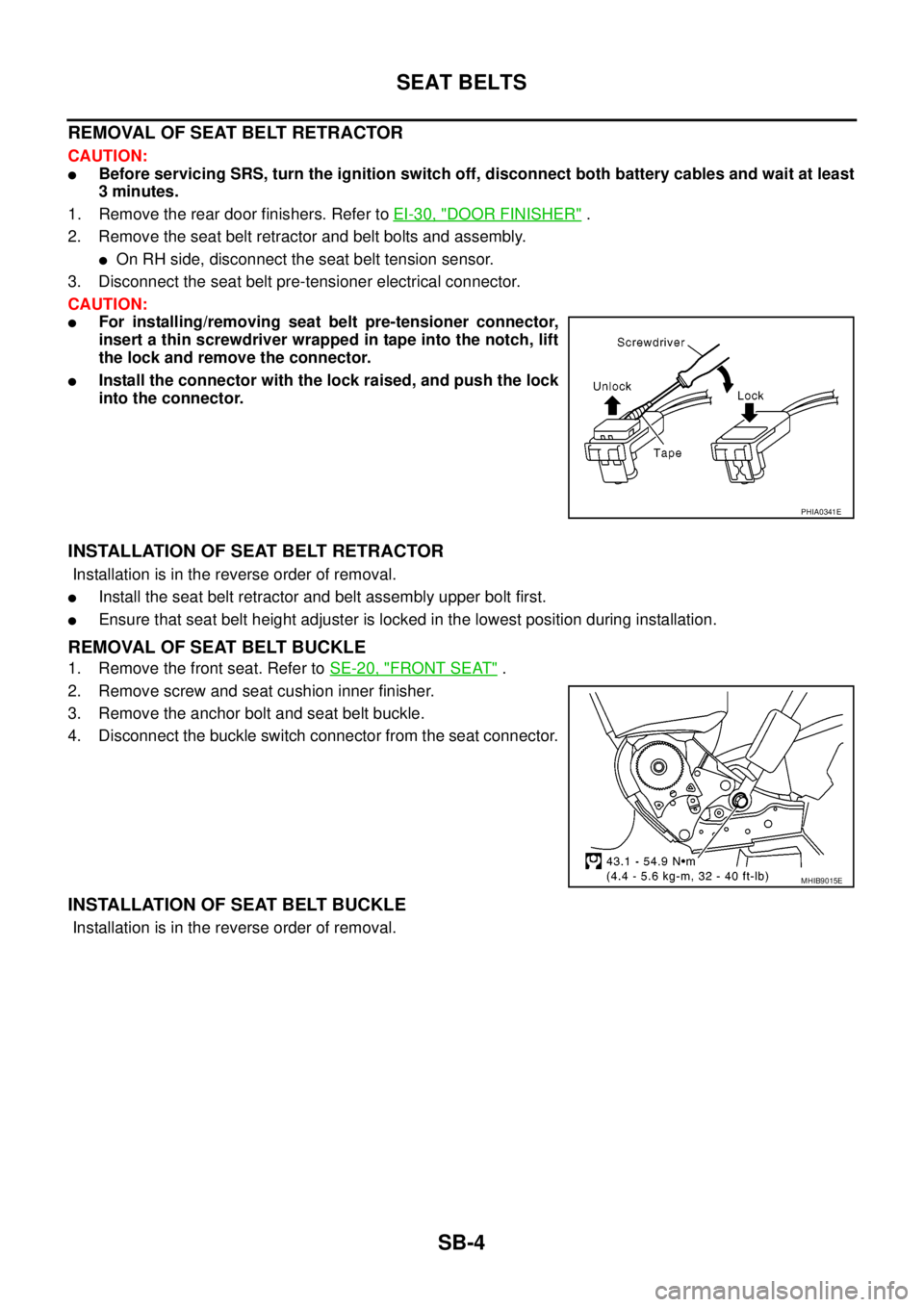
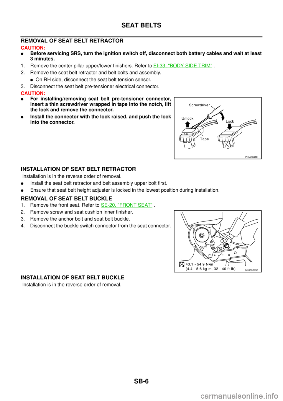
CAUTION:
lBefore servicing SRS, turn the ignition switch off, disconnect both battery cables and wait at least
3 minutes.
1. Remove the rear door finishers. Refer toEI-30, "
DOOR FINISHER".
2. Remove the seat belt retractor and belt bolts and assembly.
lOn RH side, disconnect the seat belt tension sensor.
3. Disconnect the seat belt pre-tensioner electrical connector.
CAUTION:
lFor installing/removing seat belt pre-tensioner connector,
insert a thin screwdriver wrapped in tape into the notch, lift
the lock and remove the connector.
lInstall the connector with the lock raised, and push the lock
into the connector.
INSTALLATION OF SEAT BELT RETRACTOR
Installation is in the reverse order of removal.
lInstall the seat belt retractor and belt assembly upper bolt first.
lEnsure that seat belt height adjuster is locked in the lowest position during installation.
REMOVAL OF SEAT BELT BUCKLE
1. Remove the front seat. Refer toSE-20, "FRONT SEAT".
2. Remove screw and seat cushion inner finisher.
3. Remove the anchor bolt and seat belt buckle.
4. Disconnect the buckle switch connector from the seat connector.
INSTALLATION OF SEAT BELT BUCKLE
Installation is in the reverse order of removal.
PHIA0341E
MHIB9015E
Page 2823 of 3171

SB-6
SEAT BELTS
REMOVALOFSEATBELTRETRACTOR
CAUTION:
lBefore servicing SRS, turn the ignition switch off, disconnect both battery cables and wait at least
3 minutes.
1. Remove the center pillar upper/lower finishers. Refer toEI-33, "
BODY SIDE TRIM".
2. Remove the seat belt retractor and belt bolts and assembly.
lOn RH side, disconnect the seat belt tension sensor.
3. Disconnect the seat belt pre-tensioner electrical connector.
CAUTION:
lFor installing/removing seat belt pre-tensioner connector,
insert a thin screwdriver wrapped in tape into the notch, lift
the lock and remove the connector.
lInstall the connector with the lock raised, and push the lock
into the connector.
INSTALLATION OF SEAT BELT RETRACTOR
Installation is in the reverse order of removal.
lInstall the seat belt retractor and belt assembly upper bolt first.
lEnsure that seat belt height adjuster is locked in the lowest position during installation.
REMOVAL OF SEAT BELT BUCKLE
1. Remove the front seat. Refer toSE-20, "FRONT SEAT".
2. Remove screw and seat cushion inner finisher.
3. Remove the anchor bolt and seat belt buckle.
4. Disconnect the buckle switch connector from the seat connector.
INSTALLATION OF SEAT BELT BUCKLE
Installation is in the reverse order of removal.
PHIA0341E
MHIB9015E