2005 NISSAN NAVARA sensor
[x] Cancel search: sensorPage 2965 of 3171

SRS-56
COLLISION DIAGNOSIS
COLLISION DIAGNOSIS
PFP:00015
For Frontal CollisionEHS001Y3
Check the SRS components using the following table.
lAfter the work is completed, perform self-diagnosis to check that no malfunction is detected. Refer to
SRS-18, "
SRS Operation Check".
SRS INSPECTION (FOR FRONTAL COLLISION)
For Side CollisionEHS001Y4
Check the SRS components using the following table.
Part SRS is activated SRS is NOT activated
Air bag module
(driver and front pas-
senger air bag mod-
ule)Replace
Install with new fas-
teners.1. Remove air bag module. Check harness cover and connectors for damage, termi-
nals for deformities, and harness for binding.
2. Install driver air bag module into the steering wheel to check fit and alignment with
the wheel.
3. Install passenger air bag module into the instrument panel to check fit with the
instrument panel.
4. If no damage is found, reinstall with new fasteners.
5. If damaged—Replace. Install air bag modules with new fasteners.
Air bag modules must be deployed before disposal.
Seat belt pre-
tensioner assembliesReplace
Install seat belt pre-
tensioner with new
fasteners.1. Remove seat belt pre-tensioners.
Check harness cover and connectors for damage, terminals for deformities, and
harness for binding.
2. Check belts for damage and anchors for loose mounting.
3. Check retractor for smooth operation.
4. Check seat belt adjuster for damage.
5. If no damage is found, reinstall seat belt pre-tensioner assembly.
6. If damaged—Replace. Install the seat belt pre-tensioners with new fasteners.
Seat belt pre-tensioners must be deployed before disposal.
Diagnosis sensor unit Replace
Install with new fas-
teners.1. Check case for dents, cracks or deformities.
2. Check connectors for damage, and terminals for deformities.
3. If no damage is found, reinstall with new fasteners.
4. If damaged—Replace. Install diagnosis sensor unit with new fasteners.
Steering wheel 1. Visually check steering wheel for deformities.
2. Check harness (built into steering wheel) and connectors for damage, and terminals for deformities.
3. Install driver air bag module into the steering wheel to check fit and alignment with the wheel.
4. Check steering wheel for excessive free play.
5. If no damage is found, reinstall.
6. If damaged—Replace.
Spiral cable Replace the spiral
cable.1. Visually check spiral cable and combination switch for damage.
2. Check connectors and protective tape for damage.
3. Check steering wheel for noise, binding or heavy operation.
4. If no damage is found, reinstall.
5. If damaged—Replace.
Harness and connec-
tors1. Check connectors for poor connection, damage, and terminals for deformities.
2. Check harness for binding, chafing, cuts, or deformities.
3. If no damage is found, reinstall the harness and connectors.
4. If damaged—Replace the damaged harness. Do not attempt to repair, splice or modify any SRS harness.
Instrument panel
Replace the instru-
ment panel assembly.1. Visually check instrument panel for damage.
2. If no damage is found, reinstall the instrument panel.
3. If damaged—Replace the instrument panel.
Page 2966 of 3171
COLLISION DIAGNOSIS
SRS-57
C
D
E
F
G
I
J
K
L
MA
B
SRS
lAfter the work is completed, perform self-diagnosis to check that no malfunction is detected. Refer to
SRS-18, "
SRS Operation Check".
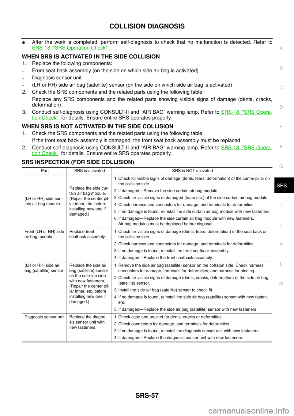
WHEN SRS IS ACTIVATED IN THE SIDE COLLISION
1. Replace the following components:
–Front seat back assembly (on the side on which side air bag is activated)
–Diagnosis sensor unit
–(LH or RH) side air bag (satellite) sensor (on the side on which side air bag is activated)
2. Check the SRS components and the related parts using the following table.
–Replace any SRS components and the related parts showing visible signs of damage (dents, cracks,
deformation).
3. Conduct self-diagnosis using CONSULT-II and “AIR BAG” warning lamp. Refer toSRS-18, "
SRS Opera-
tion Check"for details. Ensure entire SRS operates properly.
WHENSRSISNOTACTIVATEDINTHESIDECOLLISION
1. Check the SRS components and the related parts using the following table.
–If the front seat back assembly is damaged, the front seat back assembly must be replaced.
2. Conduct self-diagnosis using CONSULT-II and “AIR BAG” warning lamp. Refer toSRS-18, "
SRS Opera-
tion Check"for details. Ensure entire SRS operates properly.
SRS INSPECTION (FOR SIDE COLLISION)
Part SRS is activated SRS is NOT activated
(LH or RH) side cur-
tain air bag moduleReplace the side cur-
tain air bag module.
(Repair the center pil-
lar inner, etc. before
installing new one if
damaged.)1. Check for visible signs of damage (dents, tears, deformation) of the center pillar on
the collision side.
2. If damaged—Remove the side curtain air bag module.
3. Check for visible signs of damaged (tears etc.) of the side curtain air bag module.
4. Check harness and connectors for damage, and terminals for deformities.
5. If no damage is found, reinstall the side curtain air bag module with new fasteners.
6. If damaged—Replace the side curtain air bag module with new fasteners.
Air bag modules must be deployed before disposal.
Front (LH or RH) side
air bag moduleReplace front
seatback assembly.1. Check for visible signs of damage (dents, tears, deformation) of the seat back on
the collision side.
2. Check harness and connectors for damage, and terminals for deformities.
3. If no damage is found, reinstall the front seatback assembly.
4. If damaged—Replace the front seatback assembly.
(LH or RH) side air
bag (satellite) sensorReplace the side air
bag (satellite) sensor
on the collision side
with new fasteners.
(Repair the center pil-
lar inner, etc. before
installing new one if
damaged.)1. Remove the side air bag (satellite) sensor on the collision side. Check harness
connectors for damage, terminals for deformities, and harness for binding.
2. Check for visible signs of damage (dents, cracks, deformation) of the side air bag
(satellite) sensor.
3. Install the side air bag (satellite) sensor to check fit.
4. If no damage is found, reinstall the side sir bag (satellite) sensor with new fasten-
ers.
5. If damaged—Replace the side air bag (satellite) sensor with new fasteners.
Diagnosis sensor unit Replace the diagno-
sis sensor unit with
new fasteners.1. Check case and bracket for dents, cracks or deformities.
2. Check connectors for damage, and terminals for deformities.
3. If no damage is found, reinstall the diagnosis sensor unit with new fasteners.
4. If damaged—Replace the diagnosis sensor unit with new fasteners.
Page 2969 of 3171

TF-2
DIAGNOSTIC PROCEDURE .............................. 53
COMPONENT INSPECTION .............................. 54
Transfer Control Unit .............................................. 54
DIAGNOSTIC PROCEDURE .............................. 54
Output Shaft Revolution Signal (TCM) ................... 55
DIAGNOSTIC PROCEDURE .............................. 55
Vehicle Speed Sensor (ABS) .................................. 55
DIAGNOSTIC PROCEDURE .............................. 55
4LO Switch ............................................................. 56
CONSULT-II REFERENCE VALUE IN DATA
MONITOR MODE ................................................ 56
TRANSFER CONTROL UNIT TERMINALS AND
REFERENCE VALUE .......................................... 56
DIAGNOSTIC PROCEDURE .............................. 57
COMPONENT INSPECTION .............................. 59
4WD Shift Switch .................................................... 59
CONSULT-II REFERENCE VALUE IN DATA
MONITOR MODE ................................................ 59
TRANSFER CONTROL UNIT TERMINALS AND
REFERENCE VALUE .......................................... 59
DIAGNOSTIC PROCEDURE .............................. 60
COMPONENT INSPECTION .............................. 62
Wait Detection Switch ............................................. 63
CONSULT-II REFERENCE VALUE IN DATA
MONITOR MODE ................................................ 63
TRANSFER CONTROL UNIT TERMINALS AND
REFERENCE VALUE .......................................... 63
DIAGNOSTIC PROCEDURE .............................. 64
COMPONENT INSPECTION .............................. 66
PNP Switch Signal (TCM) ...................................... 66
DIAGNOSTIC PROCEDURE .............................. 66
Actuator Motor ........................................................ 67
CONSULT-II REFERENCE VALUE IN DATA
MONITOR MODE ................................................ 67
TRANSFER CONTROL UNIT TERMINALS AND
REFERENCE VALUE .......................................... 67
DIAGNOSTIC PROCEDURE .............................. 68
COMPONENT INSPECTION .............................. 74
Actuator Position Switch ......................................... 75
CONSULT-II REFERENCE VALUE IN DATA
MONITOR MODE ................................................ 75
TRANSFER CONTROL UNIT TERMINALS AND
REFERENCE VALUE .......................................... 75
DIAGNOSTIC PROCEDURE .............................. 76
Transfer Control Device .......................................... 78
CONSULT-II REFERENCE VALUE IN DATA
MONITOR MODE ................................................ 78
TRANSFER CONTROL UNIT TERMINALS AND
REFERENCE VALUE .......................................... 78
DIAGNOSTIC PROCEDURE .............................. 79
Engine Speed Signal (ECM) ................................... 81
DIAGNOSTIC PROCEDURE .............................. 81
CAN Communication Line ...................................... 82
DIAGNOSTIC PROCEDURE .............................. 82
ATP Switch ............................................................. 82
CONSULT-II REFERENCE VALUE IN DATA
MONITOR MODE ................................................ 82
TRANSFER CONTROL UNIT TERMINALS ANDREFERENCE VALUE .......................................... 82
DIAGNOSTIC PROCEDURE ............................... 83
COMPONENT INSPECTION ............................... 85
Park/Neutral Position Switch ................................... 85
TRANSFER CONTROL UNIT TERMINALS AND
REFERENCE VALUE .......................................... 85
DIAGNOSTIC PROCEDURE ............................... 85
COMPONENT INSPECTION ............................... 87
TROUBLE DIAGNOSIS FOR SYMPTOMS .............. 88
4WD Shift Indicator Lamp and 4LO Indicator Lamp
Do Not Turn ON ...................................................... 88
SYMPTOM: .......................................................... 88
DIAGNOSTIC PROCEDURE ............................... 89
4WD Warning Lamp Does Not Turn ON ................. 91
SYMPTOM: .......................................................... 91
DIAGNOSTIC PROCEDURE ............................... 92
4WD Shift Indicator Lamp or 4LO Indicator Lamp
Does Not Change ................................................... 94
SYMPTOM: .......................................................... 94
DIAGNOSTIC PROCEDURE ............................... 95
ATP Warning Lamp Does Not Turn ON .................. 96
SYMPTOM: .......................................................... 96
DIAGNOSTIC PROCEDURE ............................... 96
4WD Shift Indicator Lamp Repeats Flashing .......... 98
SYMPTOM: .......................................................... 98
DIAGNOSTIC PROCEDURE ............................... 98
4WD Warning Lamp Flashes Slowly ....................... 99
SYMPTOM: .......................................................... 99
DIAGNOSTIC PROCEDURE ............................... 99
TRANSFER CONTROL UNIT .................................100
Removal and Installation .......................................100
REMOVAL ..........................................................100
INSTALLATION ..................................................100
FRONT OIL SEAL ...................................................101
Removal and Installation .......................................101
REMOVAL ..........................................................101
INSTALLATION ..................................................102
REAR OIL SEAL .....................................................103
Removal and Installation .......................................103
REMOVAL ..........................................................103
INSTALLATION ..................................................103
TRANSFER CONTROL DEVICE ............................105
Removal and Installation .......................................105
REMOVAL ..........................................................105
INSTALLATION ..................................................105
AIR BREATHER HOSE ...........................................107
Removal and Installation .......................................107
A/T MODELS .....................................................107
M/T MODELS .....................................................109
TRANSFER ASSEMBLY ......................................... 111
Removal and Installation ....................................... 111
REMOVAL .......................................................... 111
INSTALLATION ..................................................112
Disassembly and Assembly ..................................112
COMPONENTS .................................................112
DISASSEMBLY ..................................................114
INSPECTION AFTER DISASSEMBLY ..............119
ASSEMBLY ........................................................120
Page 2982 of 3171
4WD SYSTEM
TF-15
C
E
F
G
H
I
J
K
L
MA
B
TF
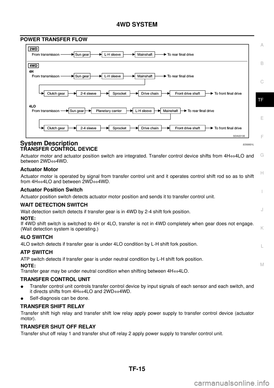
POWER TRANSFER FLOW
System DescriptionEDS0031L
TRANSFER CONTROL DEVICE
Actuator motor and actuator position switch are integrated. Transfer control device shifts from 4HÛ4LO and
between 2WDÛ4WD.
Actuator Motor
Actuator motor is operated by signal from transfer control unit and it operates control shift rod so as to shift
from 4HÛ4LO and between 2WDÛ4WD.
Actuator Position Switch
Actuator position switch detects actuator motor position and sends it to transfer control unit.
WAIT DETECTION SWITCH
Wait detection switch detects if transfer gear is in 4WD by 2-4 shift fork position.
NOTE:
If 4WD shift switch is switched to 4H or 4LO, transfer is not in 4WD completely when gear does not engage.
(Wait detection system is operating.)
4LO SWITCH
4LO switch detects if transfer gear is under 4LO condition by L-H shift fork position.
AT P S W I T C H
ATP switch detects if transfer gear is under neutral condition by L-H shift fork position.
NOTE:
Transfer gear may be under neutral condition when shifting between 4HÛ4LO.
TRANSFER CONTROL UNIT
lTransfer control unit controls transfer control device by input signals of each sensor and each switch, and
itdirectsshiftsfrom4HÛ4LO and 2WDÛ4WD.
lSelf-diagnosis can be done.
TRANSFER SHIFT RELAY
Transfer shift high relay and transfer shift low relay apply power supply to transfer control device (actuator
motor).
TRANSFER SHUT OFF RELAY
Transfer shut off relay 1 and transfer shut off relay 2 apply power supply to transfer control unit.
SDIA2213E
Page 3012 of 3171
TROUBLE DIAGNOSIS
TF-45
C
E
F
G
H
I
J
K
L
MA
B
TF
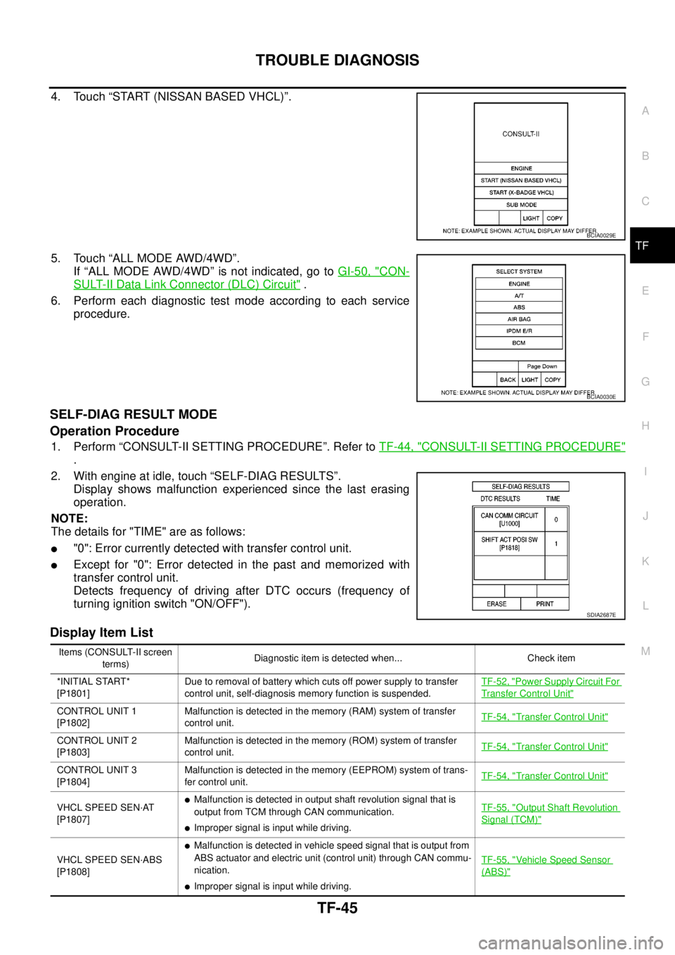
4. Touch “START (NISSAN BASED VHCL)”.
5. Touch “ALL MODE AWD/4WD”.
If “ALL MODE AWD/4WD” is not indicated, go toGI-50, "
CON-
SULT-II Data Link Connector (DLC) Circuit".
6. Perform each diagnostic test mode according to each service
procedure.
SELF-DIAG RESULT MODE
Operation Procedure
1. Perform “CONSULT-II SETTING PROCEDURE”. Refer toTF-44, "CONSULT-II SETTING PROCEDURE"
.
2. With engine at idle, touch “SELF-DIAG RESULTS”.
Display shows malfunction experienced since the last erasing
operation.
NOTE:
The details for "TIME" are as follows:
l"0": Error currently detected with transfer control unit.
lExcept for "0": Error detected in the past and memorized with
transfer control unit.
Detects frequency of driving after DTC occurs (frequency of
turning ignition switch "ON/OFF").
Display Item List
BCIA0029E
BCIA0030E
SDIA2687E
Items (CONSULT-II screen
terms)Diagnostic item is detected when... Check item
*INITIAL START*
[P1801]Due to removal of battery which cuts off power supply to transfer
control unit, self-diagnosis memory function is suspended.TF-52, "
Power Supply Circuit For
Transfer Control Unit"
CONTROL UNIT 1
[P1802]Malfunction is detected in the memory (RAM) system of transfer
control unit.TF-54, "Transfer Control Unit"
CONTROL UNIT 2
[P1803]Malfunction is detected in the memory (ROM) system of transfer
control unit.TF-54, "Transfer Control Unit"
CONTROL UNIT 3
[P1804]Malfunction is detected in the memory (EEPROM) system of trans-
fer control unit.TF-54, "Transfer Control Unit"
VHCL SPEED SEN·AT
[P1807]lMalfunction is detected in output shaft revolution signal that is
output from TCM through CAN communication.
lImproper signal is input while driving.TF-55, "
Output Shaft Revolution
Signal (TCM)"
VHCL SPEED SEN·ABS
[P1808]
lMalfunction is detected in vehicle speed signal that is output from
ABS actuator and electric unit (control unit) through CAN commu-
nication.
lImproper signal is input while driving.TF-55, "
Vehicle Speed Sensor
(ABS)"
Page 3017 of 3171
TF-50
TROUBLE DIAGNOSIS
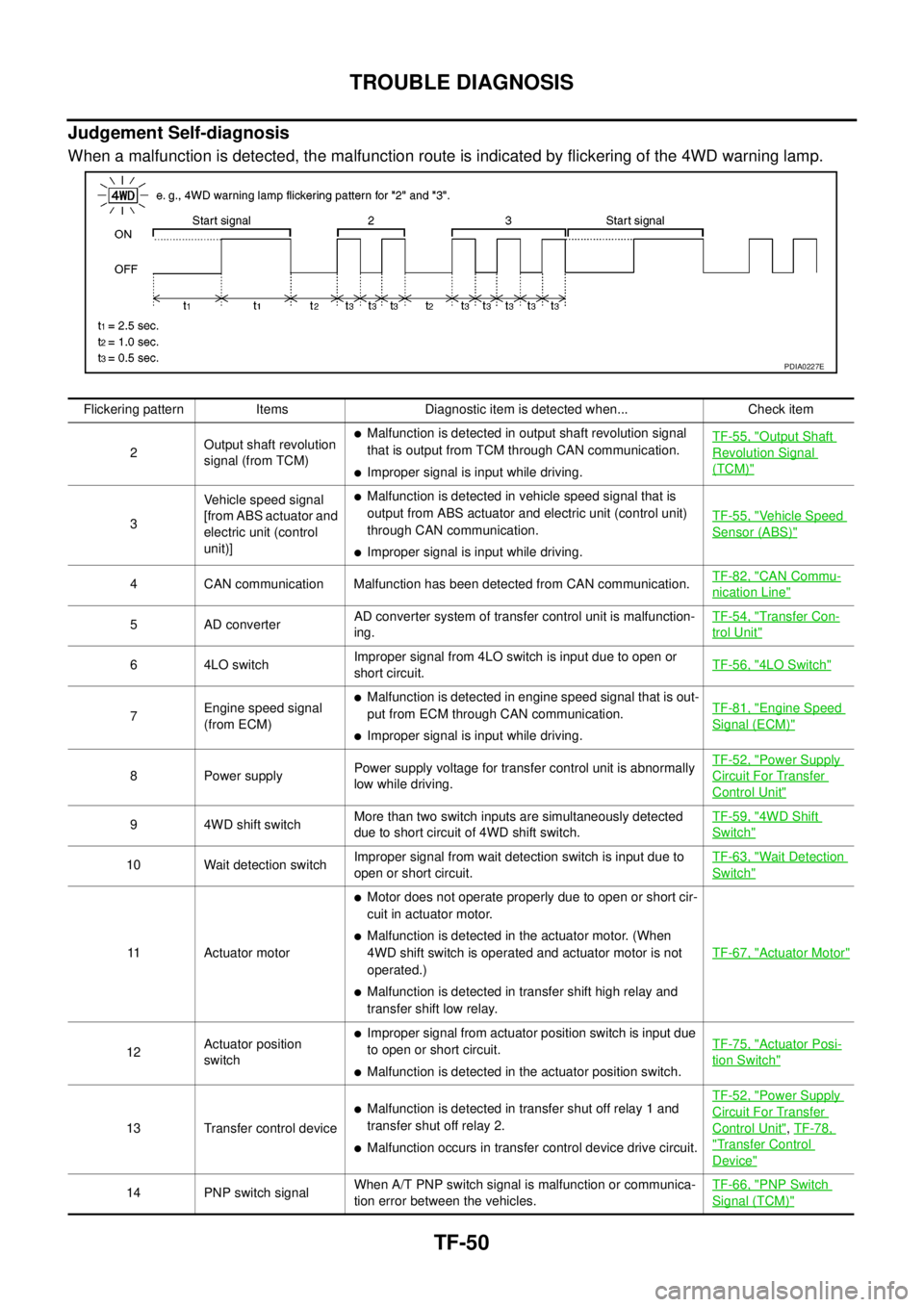
Judgement Self-diagnosis
When a malfunction is detected, the malfunction route is indicated by flickering of the 4WD warning lamp.
PDIA0227E
Flickering pattern Items Diagnostic item is detected when... Check item
2Output shaft revolution
signal (from TCM)
lMalfunction is detected in output shaft revolution signal
that is output from TCM through CAN communication.
lImproper signal is input while driving.TF-55, "
Output Shaft
Revolution Signal
(TCM)"
3Vehicle speed signal
[from ABS actuator and
electric unit (control
unit)]
lMalfunction is detected in vehicle speed signal that is
output from ABS actuator and electric unit (control unit)
through CAN communication.
lImproper signal is input while driving.TF-55, "
Vehicle Speed
Sensor (ABS)"
4 CAN communication Malfunction has been detected from CAN communication.TF-82, "CAN Commu-
nication Line"
5 AD converterAD converter system of transfer control unit is malfunction-
ing.TF-54, "Transfer Con-
trol Unit"
6 4LO switchImproper signal from 4LO switch is input due to open or
short circuit.TF-56, "4LO Switch"
7Engine speed signal
(from ECM)
lMalfunction is detected in engine speed signal that is out-
put from ECM through CAN communication.
lImproper signal is input while driving.TF-81, "
Engine Speed
Signal (ECM)"
8 Power supplyPower supply voltage for transfer control unit is abnormally
low while driving.TF-52, "
Power Supply
Circuit For Transfer
Control Unit"
9 4WD shift switchMore than two switch inputs are simultaneously detected
due to short circuit of 4WD shift switch.TF-59, "4WD Shift
Switch"
10 Wait detection switchImproper signal from wait detection switch is input due to
open or short circuit.TF-63, "Wait Detection
Switch"
11 Actuator motor
lMotor does not operate properly due to open or short cir-
cuit in actuator motor.
lMalfunction is detected in the actuator motor. (When
4WD shift switch is operated and actuator motor is not
operated.)
lMalfunction is detected in transfer shift high relay and
transfer shift low relay.TF-67, "
Actuator Motor"
12Actuator position
switch
lImproper signal from actuator position switch is input due
to open or short circuit.
lMalfunction is detected in the actuator position switch.TF-75, "
Actuator Posi-
tion Switch"
13 Transfer control device
lMalfunction is detected in transfer shut off relay 1 and
transfer shut off relay 2.
lMalfunction occurs in transfer control device drive circuit.TF-52, "
Power Supply
Circuit For Transfer
Control Unit",TF-78,
"Transfer Control
Device"
14 PNP switch signalWhen A/T PNP switch signal is malfunction or communica-
tion error between the vehicles.TF-66, "PNP Switch
Signal (TCM)"
Page 3022 of 3171
TROUBLE DIAGNOSIS FOR SYSTEM
TF-55
C
E
F
G
H
I
J
K
L
MA
B
TF
2.PERFORM SELF-DIAGNOSIS (WITH CONSULT-II)
With CONSULT-II
1. Turn ignition switch “ON”. (Do not start engine.)
2. Select “SELF-DIAG RESULTS” mode for “ALL MODE AWD/4WD” with CONSULT-II.
3. Touch “ERASE”.
4. Turn ignition switch “OFF” and wait at least 10 seconds.
5. Perform the self-diagnosis again.
Is the
“CONTROL UNIT 1 [P1802]”,“CONTROL UNIT 2 [P1803]”,“CONTROL UNIT 3 [P1804]”or“CONTROL
UNIT 4 [P1809]”displayed?
YES >> Replace transfer control unit. Refer toTF-100, "Removal and Installation".
NO >>INSPECTION END
3.PERFORM SELF-DIAGNOSIS (WITHOUT CONSULT-II)
Without CONSULT-II
1. Perform the self-diagnosis and then erase self-diagnostic results. Refer toTF-49, "
SELF-DIAGNOSTIC
PROCEDURE (WITHOUT CONSULT-II)"andTF-51, "ERASE SELF-DIAGNOSIS".
2. Perform the self-diagnosis again.
Do the self-diagnostic results indicate AD converter?
YES >> Replace transfer control unit. Refer toTF-100, "Removal and Installation".
NO >>INSPECTION END
Output Shaft Revolution Signal (TCM)EDS00320
DIAGNOSTIC PROCEDURE
1.CHECK DTC WITH TCM
Perform self-diagnosis with TCM. Refer toAT-80, "
SELF-DIAGNOSTIC RESULT MODE".
Is any malfunction detected by self-diagnosis?
YES >> Check the malfunctioning system.
NO >> GO TO 2.
2.CHECK TRANSFER CONTROL UNIT
Check transfer control unit input/output signal. Refer toTF-38, "
Transfer Control Unit Input/Output Signal Ref-
erence Values".
OK or NG
OK >> GO TO 3.
NG >> Check transfer control unit pin terminals for damage or loose connection with harness connector.
If any items are damaged, repair or replace damaged parts.
3.CHECK DTC
Perform the self-diagnosis, after driving a vehicle for a while.
OK or NG
OK >>INSPECTION END
NG >> Perform self-diagnosis with TCM again. Refer toAT-80, "
SELF-DIAGNOSTIC RESULT MODE".
Vehicle Speed Sensor (ABS)EDS00321
DIAGNOSTIC PROCEDURE
1.CHECK DTC WITH ABS ACTUATOR AND ELECTRIC UNIT (CONTROL UNIT)
Perform self-diagnosis with ABS actuator and electric unit (control unit). Refer toBRC-18, "
Self-Diagnosis".
Is any malfunction detected by self-diagnosis?
YES >> Check the malfunctioning system.
NO >> GO TO 2.
Page 3117 of 3171

WW-6
FRONT WIPER AND WASHER SYSTEM
INTERMITTENT OPERATION
When front wiper switch is turned to INT position, wiper performs intermittent operation, low-speed operation,
and high-speed operation according to water drop increase rate on windshield detected by light and rain sen-
sor. If light and rain sensor malfunctions, it operates as vehicle speed sensing wiper during driving and oper-
ates intermittent operation according to INT-volume switch with vehicle stopped. During this time, BCM
controls each operation.
The BCM then sends a front wiper (HI or LOW) request signal with CAN communication.
lfrom BCM terminals 21 and 22
lto IPDM E/R terminals 39 and 40.
When the BCM determines that combination switch status is front wiper intermittent ON, it performs the follow-
ing operations.
lBCM detects intermittent wiper dial position.
lBCM sends front wiper request signal (HI or LOW) to IPDM E/R at calculated operation interval.
When IPDM E/R receives front wiper request signal (HI or LOW), it supplies ground to energize the front wiper
main relay and front wiper LOW/HIGH relay. It then sends an auto-stop signal to the BCM, and conducts inter-
mittent front wiper motor operation.
AUTO STOP OPERATION
When the wiper arms are not located at the base of the windshield, and the wiper switch is turned OFF, the
wiper motor will continue to operate until the wiper arms reach the windshield base. When the wiper arms
reach the base of windshield, front wiper motor terminals 2 and 5 are connected.
Ground is supplied
lto IPDM E/R terminal 43
lthrough front wiper motor terminal 5
lthrough front wiper motor terminal 2
lthrough grounds E21, E41 and E61.
The IPDM E/R sends an auto stop operation signal to the BCM with CAN communication.
When the BCM receives an auto stop operation signal, the BCM sends wiper stop signal to the IPDM E/R over
CAN communication lines. The IPDM E/R then de-energizes the front wiper main relay.
The wiper motor will then stop the wiper arms at the STOP position.
FRONT WASHER OPERATION
When the ignition switch is in the ON or START position, and the front washer switches are OFF, the front
washer motor is supplied power
lthrough 10A fuse [No. 15, located in fuse block (J/B)]
lthrough combination switch (wiper switch) terminal 2
lthrough combination switch (wiper switch) terminal 4
lto front washer motor terminal 1.
When the front wiper switch is in the front washer position, the BCM detects a front washer signal request
through the combination switch (wiper switch) reading function.
Combination switch ground is supplied
lto front washer motor terminal 2
lthrough combination switch (wiper switch) terminal 3
lthrough combination switch (wiper switch) terminal 9
lthrough grounds M21, M80 and M83.
With ground supplied, the front washer motor is operated in the front direction.
When the BCM detects that front washer motor has operated for 0.4 seconds or longer, the BCM uses CAN
communication and sends a wiper request signal to the IPDM E/R for low speed operation of wipers.
When the BCM detects that the washer switch is OFF, low speed operation cycles approximately 3 times and
then stops.