2005 NISSAN NAVARA sensor
[x] Cancel search: sensorPage 2932 of 3171
![NISSAN NAVARA 2005 Repair Workshop Manual TROUBLE DIAGNOSIS
SRS-23
C
D
E
F
G
I
J
K
L
MA
B
SRS
PRE-TEN FRONT LH
[OPEN]
[B1086]lThe circuit for front LH seat belt pre-tensioner is open. 1. Visually check the wiring harness
connections.
2. Repla NISSAN NAVARA 2005 Repair Workshop Manual TROUBLE DIAGNOSIS
SRS-23
C
D
E
F
G
I
J
K
L
MA
B
SRS
PRE-TEN FRONT LH
[OPEN]
[B1086]lThe circuit for front LH seat belt pre-tensioner is open. 1. Visually check the wiring harness
connections.
2. Repla](/manual-img/5/57362/w960_57362-2931.png)
TROUBLE DIAGNOSIS
SRS-23
C
D
E
F
G
I
J
K
L
MA
B
SRS
PRE-TEN FRONT LH
[OPEN]
[B1086]lThe circuit for front LH seat belt pre-tensioner is open. 1. Visually check the wiring harness
connections.
2. Replace the harness if it has visible
damage.
3. Replace front LH seat belt pre-
tensioner.
(Before disposal, it must be
deployed.)
4. Replace the air bag diagnosis sen-
sor unit.
5. Replace the related harness. PRE-TEN FRONT LH
[VB-SHORT]
[B1087]
lThe circuit for front LH seat belt pre-tensioner is shorted to
some power supply circuit.
PRE-TEN FRONT LH
[GND-SHORT]
[B1088]
lThe circuit for front LH seat belt pre-tensioner is shorted to
ground.
PRE-TEN FRONT LH
[SHORT]
[B1089]
lThe circuits for the front LH seat belt pre-tensioner are
shorted to each other.
PRE-TEN FRONT RH
[OPEN]
[B1081]
lThe circuit for front RH seat belt pre-tensioner is open. 1. Visually check the wiring harness
connections.
2. Replace the harness if it has visible
damage.
3. Replace front RH seat belt pre-
tensioner.
(Before disposal, it must be
deployed.)
4. Replace the air bag diagnosis sen-
sor unit.
5. Replace the related harness. PRE-TEN FRONT RH
[VB-SHORT]
[B1082]
lThe circuit for front RH seat belt pre-tensioner is shorted to
some power supply circuit.
PRE-TEN FRONT RH
[GND-SHORT]
[B1083]
lThe circuit for front RH seat belt pre-tensioner is shorted to
ground.
PRE-TEN FRONT RH
[SHORT]
[B1084]
lThe circuits for the front RH seat belt pre-tensioner are
shorted to each other.
CURTAIN MODULE LH
[OPEN]
[B1150]
lThe circuit for LH side curtain air bag module is open. 1. Visually check the wiring harness
connection.
2. Replace the harness if it has visible
damage.
3. Replace LH side curtain air bag
module.
(Before disposal, it must be
deployed.)
4. Replace the air bag diagnosis sen-
sor unit.
5. Replace the related harness. CURTAIN MODULE LH
[VB-SHORT]
[B1151]
lThe circuit for LH side curtain air bag module is shorted to
some power supply circuits.
CURTAIN MODULE LH
[GND-SHORT]
[B1152]
lThe circuit for LH side curtain air bag module is shorted to
ground.
CURTAIN MODULE LH
[SHORT]
[B1153]
lThe circuits for the LH side curtain air bag module are
shorted to each other.
CURTAIN MODULE RH
[OPEN]
[B1145]
lThe circuit for RH side curtain air bag module is open. 1. Visually check the wiring harness
connection.
2. Replace the harness if it has visible
damage.
3. Replace RH side curtain air bag
module.
(Before disposal, it must be
deployed.)
4. Replace the air bag diagnosis sen-
sor unit.
5. Replace the related harness. CURTAIN MODULE RH
[VB-SHORT]
[B1146]
lThe circuit for RH side curtain air bag module is shorted to
some power supply circuits.
CURTAIN MODULE RH
[GND-SHORT]
[B1147]
lThe circuit for RH side curtain air bag module is shorted to
ground.
CURTAIN MODULE RH
[SHORT]
[B1148]
lThe circuits for the RH side curtain air bag module are
shorted to each other.
CONTROL UNIT
[B1XXX]
lAir bag diagnosis sensor unit is malfunctioning. 1. Visually check the wiring harness
connection.
2. Replace the harness if it has visible
damage.
3. Replace the air bag diagnosis sen-
sor unit. Diagnostic item ExplanationRepair order
Recheck SRS at each replacement
Page 2938 of 3171
![NISSAN NAVARA 2005 Repair Workshop Manual TROUBLE DIAGNOSIS
SRS-29
C
D
E
F
G
I
J
K
L
MA
B
SRS
SIDE MODULE RH
[OPEN]
[B1129]lFront RH side air bag module circuit is open. 1. Visually check the wiring harness
connection.
2. Replace the harness NISSAN NAVARA 2005 Repair Workshop Manual TROUBLE DIAGNOSIS
SRS-29
C
D
E
F
G
I
J
K
L
MA
B
SRS
SIDE MODULE RH
[OPEN]
[B1129]lFront RH side air bag module circuit is open. 1. Visually check the wiring harness
connection.
2. Replace the harness](/manual-img/5/57362/w960_57362-2937.png)
TROUBLE DIAGNOSIS
SRS-29
C
D
E
F
G
I
J
K
L
MA
B
SRS
SIDE MODULE RH
[OPEN]
[B1129]lFront RH side air bag module circuit is open. 1. Visually check the wiring harness
connection.
2. Replace the harness if it has visible
damage.
3. Replace front RH seat back assem-
bly (front RH side air bag module).
(Before disposal, it must be
deployed.)
4. Replace the air bag diagnosis sen-
sor unit.
5. Replace the related harness. SIDE MODULE RH
[VB-SHORT]
[B1130]
lFront RH side air bag module circuit is shorted to some
power supply circuit.
SIDE MODULE RH
[GND-SHORT]
[B1131]
lFront RH side air bag module circuit is shorted to ground.
SIDE MODULE RH
[SHORT]
[B1132]
lFront RH side air bag module circuits are shorted to each
other.
SATELLITE SENS LH
[UNIT FAIL]
[ B 111 8 ] o r [ B 111 9 ]
SATELLITE SENS LH
[COMM FAIL]
[B1120]
lLH side air bag (satellite) sensor 1. Visually check the wiring harness
connection.
2. Replace the harness if it has visible
damage.
3. Replace the LH side air bag (satel-
lite) sensor.
4. Replace the air bag diagnosis sen-
sor unit.
5. Replace the related harness.
SATELLITE SENS RH
[UNIT FAIL]
[ B 111 3 ] o r [ B 111 4 ]
SATELLITE SENS RH
[COMM FAIL]
[B1115]
lRH side air bag (satellite) sensor 1. Visually check the wiring harness
connection.
2. Replace the harness if it has visible
damage.
3. Replace the RH side air bag (satel-
lite) sensor.
4. Replace the air bag diagnosis sen-
sor unit.
5. Replace the related harness.
PRE-TEN FRONT LH
[OPEN]
[B1086]
lThe circuit for front LH seat belt pre-tensioner is open. 1. Visually check the wiring harness
connections.
2. Replace the harness if it has visible
damage.
3. Replace front LH seat belt pre-
tensioner.
(Before disposal, it must be
deployed.)
4. Replace the air bag diagnosis sen-
sor unit.
5. Replace the related harness. PRE-TEN FRONT LH
[VB-SHORT]
[B1087]
lThe circuit for front LH seat belt pre-tensioner is shorted to
some power supply circuit.
PRE-TEN FRONT LH
[GND-SHORT]
[B1088]
lThe circuit for front LH seat belt pre-tensioner is shorted to
ground.
PRE-TEN FRONT LH
[SHORT]
[B1089]
lThe circuits for the front LH seat belt pre-tensioner are
shorted to each other.
PRE-TEN FRONT RH
[OPEN]
[B1081]
lThe circuit for front RH seat belt pre-tensioner is open. 1. Visually check the wiring harness
connections.
2. Replace the harness if it has visible
damage.
3. Replace front RH seat belt pre-
tensioner.
(Before disposal, it must be
deployed.)
4. Replace the air bag diagnosis sen-
sor unit.
5. Replace the related harness. PRE-TEN FRONT RH
[VB-SHORT]
[B1082]
lThe circuit for front RH seat belt pre-tensioner is shorted to
some power supply circuit.
PRE-TEN FRONT RH
[GND-SHORT]
[B1083]
lThe circuit for front RH seat belt pre-tensioner is shorted to
ground.
PRE-TEN FRONT RH
[SHORT]
[B1084]
lThe circuits for the front RH seat belt pre-tensioner are
shorted to each other. Diagnostic item ExplanationRepair order
Recheck SRS at each replacement
Page 2939 of 3171

SRS-30
TROUBLE DIAGNOSIS
Trouble Diagnosis Without CONSULT-II
EHS001XP
DIAGNOSTIC PROCEDURE 6
Inspect SRS Malfunction Using "AIR BAG" Warning Lamp—Diagnosis Mode
NOTE:
SRS will not enter Diagnosis mode if no malfunction is detected in User mode.
1. Turn ignition switch ON.
2. After “AIR BAG” warning lamp lights for 7 seconds, turn ignition switch OFF within 1 second.
3. Wait more than 3 seconds.
4. Repeat steps 1 to 3 two more times (3 times total).
5. Turn ignition switch ON.
SRS is now in Diagnosis mode.
"AIR BAG" warning lamp operates in Diagnosis mode as follows:
CURTAIN MODULE LH
[OPEN]
[B1150]lThe circuit for LH side curtain air bag module is open. 1. Visually check the wiring harness
connection.
2. Replace the harness if it has visible
damage.
3. Replace LH side curtain air bag
module.
(Before disposal, it must be
deployed.)
4. Replace the air bag diagnosis sen-
sor unit.
5. Replace the related harness. CURTAIN MODULE LH
[VB-SHORT]
[B1151]
lThe circuit for LH side curtain air bag module is shorted to
some power supply circuits.
CURTAIN MODULE LH
[GND-SHORT]
[B1152]
lThe circuit for LH side curtain air bag module is shorted to
ground.
CURTAIN MODULE LH
[SHORT]
[B1153]
lThe circuits for the LH side curtain air bag module are
shorted to each other.
CURTAIN MODULE RH
[OPEN]
[B1145]
lThe circuit for RH side curtain air bag module is open. 1. Visually check the wiring harness
connection.
2. Replace the harness if it has visible
damage.
3. Replace RH side curtain air bag
module.
(Before disposal, it must be
deployed.)
4. Replace the air bag diagnosis sen-
sor unit.
5. Replace the related harness. CURTAIN MODULE RH
[VB-SHORT]
[B1146]
lThe circuit for RH side curtain air bag module is shorted to
some power supply circuits.
CURTAIN MODULE RH
[GND-SHORT]
[B1147]
lThe circuit for RH side curtain air bag module is shorted to
ground.
CURTAIN MODULE RH
[SHORT]
[B1148]
lThe circuits for the RH side curtain air bag module are
shorted to each other.
CONTROL UNIT
[B1XXX]
lAir bag diagnosis sensor unit is malfunctioning. 1. Visually check the wiring harness
connection.
2. Replace the harness if it has visible
damage.
3. Replace the air bag diagnosis sen-
sor unit. Diagnostic item ExplanationRepair order
Recheck SRS at each replacement
Page 2943 of 3171
SRS-34
TROUBLE DIAGNOSIS
Trouble Diagnosis: “AIR BAG” Warning Lamp Does Not Turn OFF
EHS001XQ
DIAGNOSTIC PROCEDURE 7
1.CHECK CONDITION OF AIR BAG MODULES
Inspect for any deployed air bag modules or seat belt pre-tensioners.
Are any air bag modules or seat belt pre-tensioners deployed?
Yes >> Refer toSRS-56, "COLLISION DIAGNOSIS".
No >> GO TO 2.
2.CHECK THE AIR BAG FUSE
Check 10A fuse [No. 13, located in the fuse block (J/B)].
Refer toPG-4, "
POWER SUPPLY ROUTING CIRCUIT".
OK or NG
OK >> GO TO 4.
NG >> GO TO 3.
3.CHECK AIR BAG FUSE AGAIN
Replace 10A fuse [No. 13, located in the fuse block (J/B)] and turn ignition switch ON.
Does the fuse blow again?
Yes >> Repair or replace main harness.
No >> Inspection End.
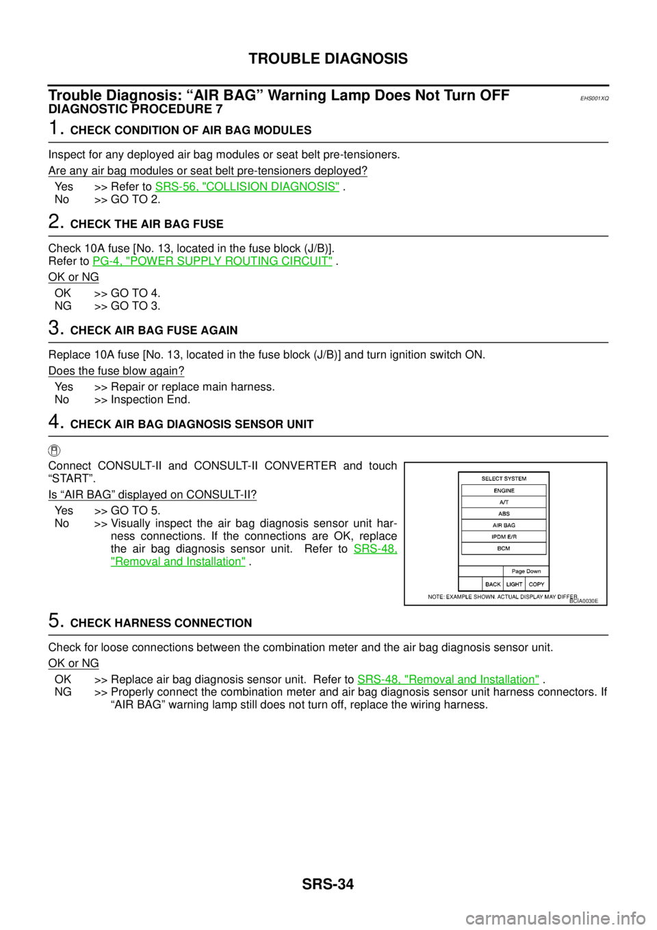
4.CHECK AIR BAG DIAGNOSIS SENSOR UNIT
Connect CONSULT-II and CONSULT-II CONVERTER and touch
“START”.
Is
“AIR BAG”displayed on CONSULT-II?
Yes >>GOTO5.
No >> Visually inspect the air bag diagnosis sensor unit har-
ness connections. If the connections are OK, replace
the air bag diagnosis sensor unit. Refer toSRS-48,
"Removal and Installation".
5.CHECK HARNESS CONNECTION
Check for loose connections between the combination meter and the air bag diagnosis sensor unit.
OK or NG
OK >> Replace air bag diagnosis sensor unit. Refer toSRS-48, "Removal and Installation".
NG >> Properly connect the combination meter and air bag diagnosis sensor unit harness connectors. If
“AIR BAG” warning lamp still does not turn off, replace the wiring harness.
BCIA0030E
Page 2944 of 3171
TROUBLE DIAGNOSIS
SRS-35
C
D
E
F
G
I
J
K
L
MA
B
SRS
Trouble Diagnosis: “AIR BAG” Warning Lamp Does Not Turn ONEHS001XR
DIAGNOSTIC PROCEDURE 8
1.CHECK METER FUSE
Check the 10A fuse [No. 14, located in the fuse block (J/B)].
Refer toPG-4, "
POWER SUPPLY ROUTING CIRCUIT".
OK or NG
OK >> GO TO 3.
NG >> GO TO 2.
2.CHECK METER FUSE AGAIN
Replace 10A fuse [No. 14, located in the fuse block (J/B)] and turn ignition switch ON.
Does the fuse blow again?
Yes >> Repair or replace the related harness.
No >> Inspection End.
3.CHECK HARNESS CONNECTION BETWEEN AIR BAG DIAGNOSIS SENSOR UNIT AND COMBINA-
TION METER
Disconnect the air bag diagnosis sensor unit harness connectors and turn ignition switch ON.
Does
“AIR BAG”warninglampturnON?
Yes >> Replace the air bag diagnosis sensor unit. Refer toSRS-48, "Removal and Installation".
No >> Check the combination meter power supply circuits and ground circuits. If OK, replace combina-
tion meter.
Page 2948 of 3171
SPIRAL CABLE
SRS-39
C
D
E
F
G
I
J
K
L
MA
B
SRS
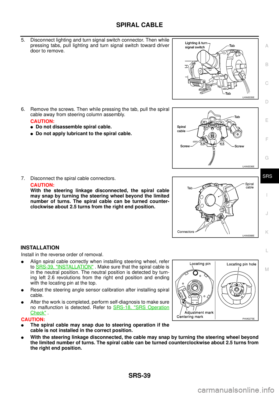
5. Disconnect lighting and turn signal switch connector. Then while
pressing tabs, pull lighting and turn signal switch toward driver
door to remove.
6. Remove the screws. Then while pressing the tab, pull the spiral
cable away from steering column assembly.
CAUTION:
lDo not disassemble spiral cable.
lDo not apply lubricant to the spiral cable.
7. Disconnect the spiral cable connectors.
CAUTION:
With the steering linkage disconnected, the spiral cable
may snap by turning the steering wheel beyond the limited
number of turns. The spiral cable can be turned counter-
clockwise about 2.5 turns from the right end position.
INSTALLATION
Install in the reverse order of removal.
lAlign spiral cable correctly when installing steering wheel, refer
toSRS-39, "
INSTALLATION". Make sure that the spiral cable is
in the neutral position. The neutral position is detected by turn-
ing left 2.6 revolutions from the right end position and ending
with the locating pin at the top.
lReset the steering angle sensor calibration after installing spiral
cable.
lAfter the work is completed, perform self-diagnosis to make sure
no malfunction is detected. Refer toSRS-18, "
SRS Operation
Check".
CAUTION:
lThe spiral cable may snap due to steering operation if the
cable is not installed in the correct position.
lWith the steering linkage disconnected, the cable may snap by turning the steering wheel beyond
the limited number of turns. The spiral cable can be turned counterclockwise about 2.5 turns from
the right end position.
LHIA0035E
LHIA0036E
LHIA0088E
PHIA0275E
Page 2955 of 3171
SRS-46
SIDE AIR BAG (SATELLITE) SENSOR
SIDE AIR BAG (SATELLITE) SENSOR
PFP:98830
Removal and InstallationEHS001XY
REMOVAL
CAUTION:
lBefore servicing the SRS, turn the ignition switch off, disconnect both battery cables and wait at
least 3 minutes.
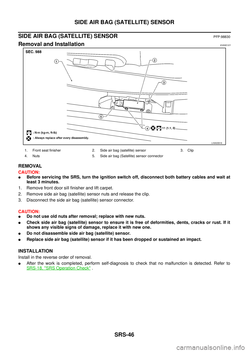
1. Remove front door sill finisher and lift carpet.
2. Remove side air bag (satellite) sensor nuts and release the clip.
3. Disconnect the side air bag (satellite) sensor connector.
CAUTION:
lDo not use old nuts after removal; replace with new nuts.
lCheck side air bag (satellite) sensor to ensure it is free of deformities, dents, cracks or rust. If it
shows any visible signs of damage, replace it with new one.
lDo not disassemble side air bag (satellite) sensor.
lReplace side air bag (satellite) sensor if it has been dropped or sustained an impact.
INSTALLATION
Install in the reverse order of removal.
lAfter the work is completed, perform self-diagnosis to check that no malfunction is detected. Refer to
SRS-18, "
SRS Operation Check".
LHIA0091E
1. Front seat finisher 2. Side air bag (satellite) sensor 3. Clip
4. Nuts 5. Side air bag (Satellite) sensor connector
Page 2957 of 3171
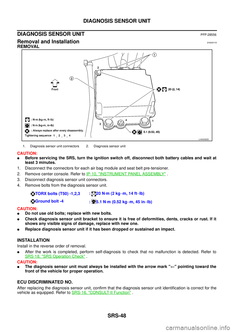
SRS-48
DIAGNOSIS SENSOR UNIT
DIAGNOSIS SENSOR UNIT
PFP:28556
Removal and InstallationEHS001Y0
REMOVAL
CAUTION:
lBefore servicing the SRS, turn the ignition switch off, disconnect both battery cables and wait at
least 3 minutes.
1. Disconnect the connectors for each air bag module and seat belt pre-tensioner.
2. Remove center console. Refer toIP-10, "
INSTRUMENT PANEL ASSEMBLY".
3. Disconnect diagnosis sensor unit connectors.
4. Remove bolts from the diagnosis sensor unit.
CAUTION:
lDo not use old bolts; replace with new bolts.
lCheck diagnosis sensor unit bracket to ensure it is free of deformities, dents, cracks or rust. If it
shows any visible signs of damage, replace with new one.
lReplace diagnosis sensor unit if it has been dropped or sustained an impact.
INSTALLATION
Install in the reverse order of removal.
lAfter the work is completed, perform self-diagnosis to check that no malfunction is detected. Refer to
SRS-18, "
SRS Operation Check".
CAUTION:
lThe diagnosis sensor unit must always be installed with the arrow mark "Ü" pointing toward the
front of the vehicle for proper operation.
ECU DISCRIMINATED NO.
After replacing the diagnosis sensor unit, confirm that the diagnosis sensor unit identification is correct for the
vehicle as equipped. Refer toSRS-16, "
CONSULT-II Function".
LHIA0092E
1. Diagnosis sensor unit connectors 2. Diagnosis sensor unit
TORX bolts (T50) -1,2,3:20N·m(2kg-m, 14 ft-lb)
Ground bolt -4
: 5.1 N·m (0.52 kg-m, 45 in-lb)