2005 NISSAN NAVARA sensor
[x] Cancel search: sensorPage 2145 of 3171
LT-62
AUTO LIGHT SYSTEM
Trouble Diagnosis Chart by Symptom
EKS00Q86
Lighting Switch InspectionEKS00Q87
1.CHECK LIGHTING SWITCH INPUT SIGNAL
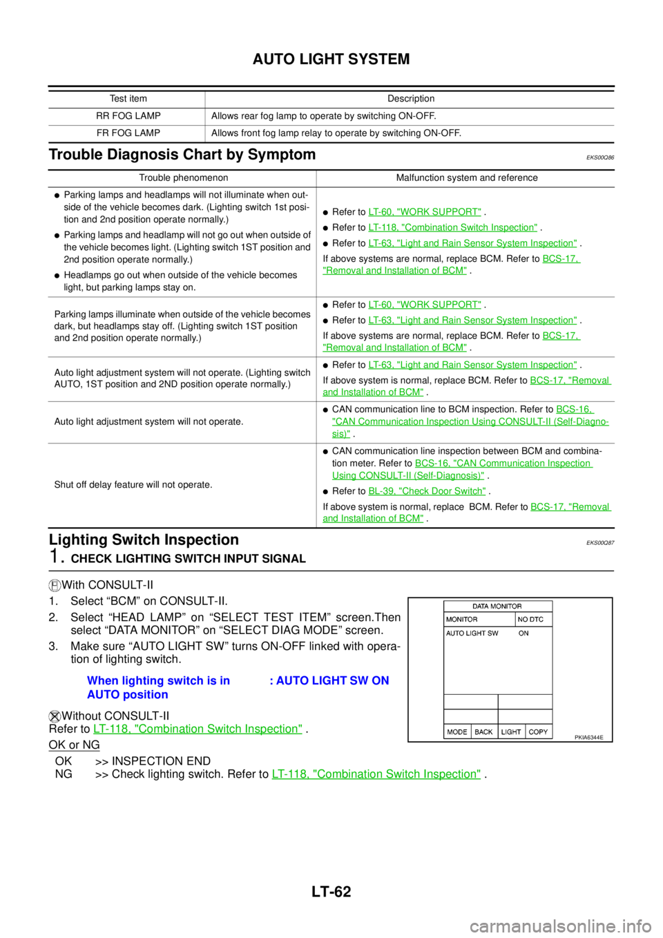
With CONSULT-II
1. Select “BCM” on CONSULT-II.
2. Select “HEAD LAMP” on “SELECT TEST ITEM” screen.Then
select “DATA MONITOR” on “SELECT DIAG MODE” screen.
3. Make sure “AUTO LIGHT SW” turns ON-OFF linked with opera-
tion of lighting switch.
Without CONSULT-II
Refer toLT- 11 8 , "
Combination Switch Inspection".
OK or NG
OK >> INSPECTION END
NG >> Check lighting switch. Refer toLT- 11 8 , "
Combination Switch Inspection".
RR FOG LAMP Allows rear fog lamp to operate by switching ON-OFF.
FR FOG LAMP Allows front fog lamp relay to operate by switching ON-OFF.Test item Description
Trouble phenomenon Malfunction system and reference
lParking lamps and headlamps will not illuminate when out-
side of the vehicle becomes dark. (Lighting switch 1st posi-
tion and 2nd position operate normally.)
lParking lamps and headlamp will not go out when outside of
the vehicle becomes light. (Lighting switch 1ST position and
2nd position operate normally.)
lHeadlamps go out when outside of the vehicle becomes
light, but parking lamps stay on.
lRefer toLT- 6 0 , "WORK SUPPORT".
lRefer toLT- 11 8 , "Combination Switch Inspection".
lRefer toLT- 6 3 , "Light and Rain Sensor System Inspection".
If above systems are normal, replace BCM. Refer toBCS-17,
"Removal and Installation of BCM".
Parking lamps illuminate when outside of the vehicle becomes
dark, but headlamps stay off. (Lighting switch 1ST position
and 2nd position operate normally.)
lRefer toLT- 6 0 , "WORK SUPPORT".
lRefer toLT- 6 3 , "Light and Rain Sensor System Inspection".
If above systems are normal, replace BCM. Refer toBCS-17,
"Removal and Installation of BCM".
Auto light adjustment system will not operate. (Lighting switch
AUTO, 1ST position and 2ND position operate normally.)
lRefer toLT- 6 3 , "Light and Rain Sensor System Inspection".
If above system is normal, replace BCM. Refer toBCS-17, "
Removal
and Installation of BCM".
Auto light adjustment system will not operate.
lCAN communication line to BCM inspection. Refer toBCS-16,
"CAN Communication Inspection Using CONSULT-II (Self-Diagno-
sis)".
Shut off delay feature will not operate.
lCAN communication line inspection between BCM and combina-
tion meter. Refer toBCS-16, "
CAN Communication Inspection
Using CONSULT-II (Self-Diagnosis)".
lRefer toBL-39, "Check Door Switch".
If above system is normal, replace BCM. Refer toBCS-17, "
Removal
and Installation of BCM".
When lighting switch is in
AUTO position: AUTO LIGHT SW ON
PKIA6344E
Page 2146 of 3171
AUTO LIGHT SYSTEM
LT-63
C
D
E
F
G
H
I
J
L
MA
B
LT
Light and Rain Sensor System InspectionEKS00Q88
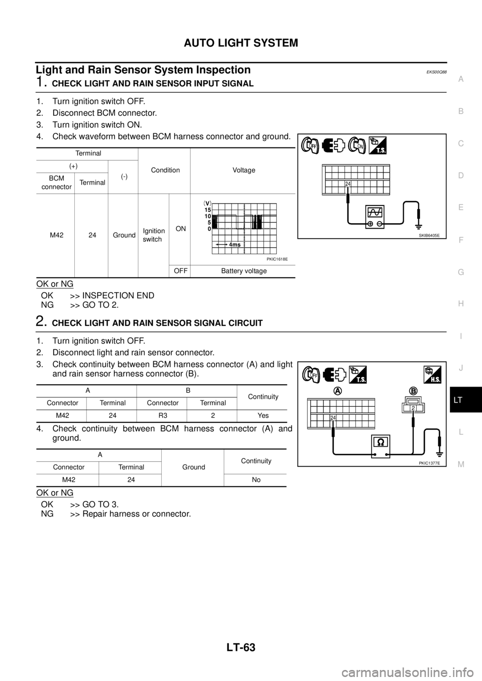
1.CHECK LIGHT AND RAIN SENSOR INPUT SIGNAL
1. Turn ignition switch OFF.
2. Disconnect BCM connector.
3. Turn ignition switch ON.
4. Check waveform between BCM harness connector and ground.
OK or NG
OK >> INSPECTION END
NG >> GO TO 2.
2.CHECK LIGHT AND RAIN SENSOR SIGNAL CIRCUIT
1. Turn ignition switch OFF.
2. Disconnect light and rain sensor connector.
3. Check continuity between BCM harness connector (A) and light
and rain sensor harness connector (B).
4. Check continuity between BCM harness connector (A) and
ground.
OK or NG
OK >> GO TO 3.
NG >> Repair harness or connector.
Terminal
Condition Voltage (+)
(-)
BCM
connectorTerminal
M42 24 GroundIgnition
switchON
OFF Battery voltage
SKIB6405E
PKIC1618E
AB
Continuity
Connector Terminal Connector Terminal
M42 24 R3 2 Yes
A
GroundContinuity
Connector Terminal
M42 24 No
PKIC1377E
Page 2147 of 3171
LT-64
AUTO LIGHT SYSTEM
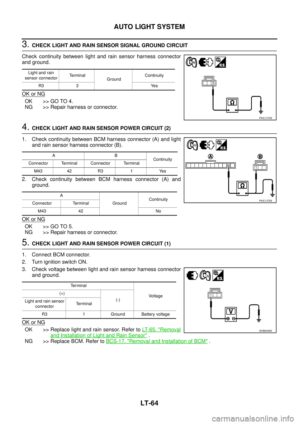
3.CHECK LIGHT AND RAIN SENSOR SIGNAL GROUND CIRCUIT
Check continuity between light and rain sensor harness connector
and ground.
OK or NG
OK >> GO TO 4.
NG >> Repair harness or connector.
4.CHECK LIGHT AND RAIN SENSOR POWER CIRCUIT (2)
1. Check continuity between BCM harness connector (A) and light
and rain sensor harness connector (B).
2. Check continuity between BCM harness connector (A) and
ground.
OK or NG
OK >> GO TO 5.
NG >> Repair harness or connector.
5.CHECK LIGHT AND RAIN SENSOR POWER CIRCUIT (1)
1. Connect BCM connector.
2. Turn ignition switch ON.
3. Check voltage between light and rain sensor harness connector
and ground.
OK or NG
OK >> Replace light and rain sensor. Refer toLT-65, "Removal
and Installation of Light and Rain Sensor".
NG >> Replace BCM. Refer toBCS-17, "
Removal and Installation of BCM".
Light and rain
sensor connectorTerminal
GroundContinuity
R3 3 Yes
PKIC1375E
AB
Continuity
Connector Terminal Connector Terminal
M43 42 R3 1 Yes
A
GroundContinuity
Connector Terminal
M43 42 No
PKIC1376E
Terminal
Voltage (+)
(-)
Light and rain sensor
connectorTe r m i n a l
R3 1 Ground Battery voltage
SKIB6406E
Page 2148 of 3171
AUTO LIGHT SYSTEM
LT-65
C
D
E
F
G
H
I
J
L
MA
B
LT
Removal and Installation of Light and Rain SensorEKS00Q89
CAUTION:
When light and rain sensor is removed from windscreen, gel/adhesive part of housing should not be
re-used.
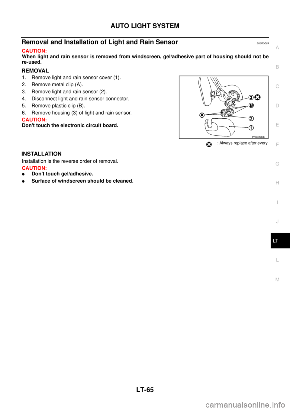
REMOVAL
1. Remove light and rain sensor cover (1).
2. Remove metal clip (A).
3. Remove light and rain sensor (2).
4. Disconnect light and rain sensor connector.
5. Remove plastic clip (B).
6. Remove housing (3) of light and rain sensor.
CAUTION:
Don't touch the electronic circuit board.
INSTALLATION
Installation is the reverse order of removal.
CAUTION:
lDon't touch gel/adhesive.
lSurface of windscreen should be cleaned.
PKIC2539E
: Always replace after every
Page 2335 of 3171
MT-18
TRANSMISSION ASSEMBLY
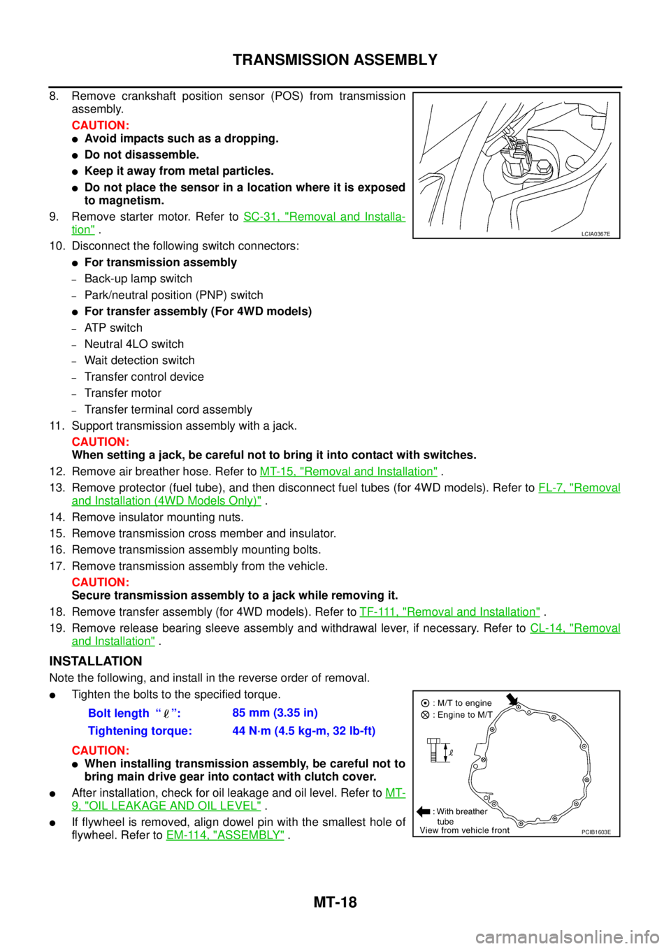
8. Remove crankshaft position sensor (POS) from transmission
assembly.
CAUTION:
lAvoid impacts such as a dropping.
lDo not disassemble.
lKeep it away from metal particles.
lDo not place the sensor in a location where it is exposed
to magnetism.
9. Remove starter motor. Refer toSC-31, "
Removal and Installa-
tion".
10. Disconnect the following switch connectors:
lFor transmission assembly
–Back-up lamp switch
–Park/neutral position (PNP) switch
lFor transfer assembly (For 4WD models)
–AT P s w i t c h
–Neutral 4LO switch
–Wait detection switch
–Transfer control device
–Transfer motor
–Transfer terminal cord assembly
11. Support transmission assembly with a jack.
CAUTION:
When setting a jack, be careful not to bring it into contact with switches.
12. Remove air breather hose. Refer toMT-15, "
Removal and Installation".
13. Remove protector (fuel tube), and then disconnect fuel tubes (for 4WD models). Refer toFL-7, "
Removal
and Installation (4WD Models Only)".
14. Remove insulator mounting nuts.
15. Remove transmission cross member and insulator.
16. Remove transmission assembly mounting bolts.
17. Remove transmission assembly from the vehicle.
CAUTION:
Secure transmission assembly to a jack while removing it.
18. Remove transfer assembly (for 4WD models). Refer toTF-111, "
Removal and Installation".
19. Remove release bearing sleeve assembly and withdrawal lever, if necessary. Refer toCL-14, "
Removal
and Installation".
INSTALLATION
Note the following, and install in the reverse order of removal.
lTighten the bolts to the specified torque.
CAUTION:
lWhen installing transmission assembly, be careful not to
bring main drive gear into contact with clutch cover.
lAfter installation, check for oil leakage and oil level. Refer toMT-
9, "OIL LEAKAGE AND OIL LEVEL".
lIf flywheel is removed, align dowel pin with the smallest hole of
flywheel. Refer toEM-114, "
ASSEMBLY".
LCIA0367E
Bolt length “ ”:85 mm (3.35 in)
Tightening torque: 44 N·m (4.5 kg-m, 32 lb-ft)
PCIB1603E
Page 2388 of 3171
MTC-1
MANUAL AIR CONDITIONER
J AIR CONDITIONER
CONTENTS
C
D
E
F
G
H
I
K
L
M
SECTIONMTC
A
B
MTC
MANUAL AIR CONDITIONER
PRECAUTIONS .......................................................... 4
Precautions for Supplemental Restraint System
(SRS)“AIRBAG”and“SEATBELTPRE-TEN-
SIONER” .................................................................. 4
Precautions for Working with HFC-134a (R-134a)..... 4
Contaminated Refrigerant ........................................ 4
General Refrigerant Precautions .............................. 5
Precautions for Refrigerant Connection ................... 5
ABOUT ONE-TOUCH JOINT ................................ 5
FEATURES OF NEW TYPE REFRIGERANT
CONNECTION ...................................................... 7
O-RING AND REFRIGERANT CONNECTION..... 9
Precautions for Servicing Compressor ................... 12
Precautions for Service Equipment ........................ 12
RECOVERY/RECYCLING EQUIPMENT ............ 12
ELECTRONIC LEAK DETECTOR ...................... 12
VACUUM PUMP ................................................. 13
MANIFOLD GAUGE SET .................................... 13
SERVICE HOSES ............................................... 13
SERVICE COUPLERS ........................................ 14
REFRIGERANT WEIGHT SCALE ...................... 14
CALIBRATING ACR4 WEIGHT SCALE .............. 14
CHARGING CYLINDER ...................................... 14
Precautions for Leak Detection Dye ....................... 14
IDENTIFICATION ................................................ 15
IDENTIFICATION LABEL FOR VEHICLE ........... 15
Wiring Diagrams and Trouble Diagnosis ................ 15
PREPARATION ......................................................... 16
Special Service Tools ............................................. 16
HFC-134a (R-134a) Service Tools and Equipment... 16
Commercial Service Tools ...................................... 19
REFRIGERATION SYSTEM ..................................... 20
Refrigerant Cycle ................................................... 20
REFRIGERANT FLOW ....................................... 20
FREEZE PROTECTION ..................................... 20
Refrigerant System Protection ............................... 20
REFRIGERANT PRESSURE SENSOR ............. 20
PRESSURE RELIEF VALVE ............................... 21
Component Layout ................................................. 22
REFRIGERATION SYSTEM ............................... 22LUBRICANT .............................................................. 24
Maintenance of Lubricant Quantity in Compressor... 24
LUBRICANT ........................................................ 24
CHECKING AND ADJUSTING ............................ 24
AIR CONDITIONER CONTROL ............................... 26
Description .............................................................. 26
Operation ................................................................ 26
AIR MIX DOOR CONTROL ................................. 26
BLOWER SPEED CONTROL ............................. 26
INTAKE DOORS CONTROL ............................... 26
MODE DOOR CONTROL ................................... 26
DEFROSTER DOOR CONTROL ........................ 26
MAGNET CLUTCH CONTROL ........................... 27
SELF-DIAGNOSTIC SYSTEM ............................ 27
Description of Control System ................................ 28
Control Operation ................................................... 28
DISPLAY SCREEN .............................................. 29
TEMPERATURE SWITCH (TEMPERATURE
CONTROL) (FRONT) .......................................... 29
RECIRCULATION () SWITCH ............................. 29
REAR WINDOW DEFOGGER SWITCH ............. 29
OFF SWITCH (BLOWER SPEED SET TO 0) ..... 29
A/C SWITCH ....................................................... 29
MODE SWITCH .................................................. 29
Discharge Air Flow ................................................. 30
FRONT ................................................................ 30
System Description ................................................. 31
SWITCHES AND THEIR CONTROL FUNCTION... 31
CAN Communication System Description .............. 32
TROUBLE DIAGNOSIS ............................................ 33
CONSULT-II ............................................................ 33
CONSULT-II BASIC OPERATION ....................... 33
DATA MONITOR ................................................. 34
How to Perform Trouble Diagnosis for Quick and
Accurate Repair ...................................................... 35
WORK FLOW ...................................................... 35
SYMPTOM TABLE .............................................. 35
Component Parts and Harness Connector Location... 36
ENGINE COMPARTMENT .................................. 36
FRONT PASSENGER COMPARTMENT ............ 37
Page 2389 of 3171

MTC-2
Schematic —LHD MODELS— ............................... 38
Wiring Diagram —A/C— —LHD MODELS— ......... 39
Schematic —RHD MODELS— ............................... 44
Wiring Diagram —A/C— —RHD MODELS— ......... 45
Front Air Control Terminals and Reference Value... 49
PIN CONNECTOR TERMINAL LAYOUT ............ 49
TERMINALS AND REFERENCE VALUE FOR
FRONT AIR CONTROL ....................................... 49
A/C System Self-diagnosis Function ...................... 51
DESCRIPTION .................................................... 51
Operational Check .................................................. 53
CHECKING BLOWER ......................................... 53
CHECKING DISCHARGE AIR ............................ 53
CHECKING RECIRCULATION ............................ 53
CHECKING TEMPERATURE DECREASE ......... 54
CHECKING TEMPERATURE INCREASE .......... 54
CHECK A/C SWITCH .......................................... 54
Power Supply and Ground Circuit for Front Air Con-
trol ........................................................................... 55
INSPECTION FLOW ........................................... 55
COMPONENT DESCRIPTION ............................ 56
DIAGNOSTIC PROCEDURE FOR A/C SYSTEM... 56
Mode Door Motor Circuit ........................................ 58
INSPECTION FLOW ........................................... 58
SYSTEM DESCRIPTION .................................... 59
COMPONENT DESCRIPTION ............................ 59
DIAGNOSTIC PROCEDURE FOR MODE
DOOR MOTOR ................................................... 59
Air Mix Door Motor Circuit ...................................... 63
INSPECTION FLOW ........................................... 63
SYSTEM DESCRIPTION .................................... 64
COMPONENT DESCRIPTION ............................ 64
DIAGNOSTIC PROCEDURE FOR AIR MIX
DOOR MOTOR (FRONT) .................................... 64
Intake Door Motor Circuit ........................................ 68
INSPECTION FLOW ........................................... 68
SYSTEM DESCRIPTION .................................... 69
COMPONENT DESCRIPTION ............................ 69
DIAGNOSTIC PROCEDURE FOR INTAKE
DOOR MOTOR ................................................... 69
Blower Motor Circuit ............................................... 71
INSPECTION FLOW ........................................... 71
SYSTEM DESCRIPTION .................................... 72
COMPONENT DESCRIPTION ............................ 72
DIAGNOSTIC PROCEDURE FOR BLOWER
MOTOR ............................................................... 73
COMPONENT INSPECTION .............................. 77
Magnet Clutch Circuit ............................................. 79
INSPECTION FLOW ........................................... 79
SYSTEM DESCRIPTION .................................... 80
DIAGNOSTIC PROCEDURE FOR MAGNET
CLUTCH .............................................................. 80
COMPONENT INSPECTION .............................. 85
Insufficient Cooling ................................................. 86
INSPECTION FLOW ........................................... 86
PERFORMANCE TEST DIAGNOSES ................ 87
PERFORMANCE CHART ................................... 89
TROUBLE DIAGNOSES FOR UNUSUAL PRES-
SURE ................................................................... 90Insufficient Heating ................................................. 93
INSPECTION FLOW ............................................ 93
Noise ....................................................................... 94
INSPECTION FLOW ............................................ 94
Self-diagnosis ......................................................... 95
INSPECTION FLOW ............................................ 95
Intake Sensor Circuit ............................................... 95
COMPONENT DESCRIPTION ............................ 95
DIAGNOSTIC PROCEDURE FOR INTAKE SEN-
SOR ..................................................................... 96
COMPONENT INSPECTION ............................... 97
CONTROL UNIT ........................................................ 98
Removal and Installation ......................................... 98
REMOVAL ............................................................ 98
INSTALLATION .................................................... 98
INTAKE SENSOR ...................................................... 99
Removal and Installation ......................................... 99
REMOVAL ............................................................ 99
INSTALLATION .................................................... 99
BLOWER MOTOR ...................................................100
Components ..........................................................100
Removal and Installation .......................................100
REMOVAL ..........................................................100
INSTALLATION ..................................................100
AIR CONDITIONER FILTER ...................................101
Removal and Installation .......................................101
FUNCTION ........................................................101
REPLACEMENT TIMING ..................................101
REPLACEMENT PROCEDURE ........................101
HEATER & COOLING UNIT ASSEMBLY ...............103
Components ..........................................................103
Removal and Installation .......................................105
REMOVAL ..........................................................105
INSTALLATION ..................................................105
HEATER CORE .......................................................106
Components ..........................................................106
Removal and Installation .......................................107
REMOVAL ..........................................................107
INSTALLATION ..................................................107
DEFROSTER DOOR MOTOR .................................108
Components ..........................................................108
Removal and Installation .......................................108
REMOVAL ..........................................................108
INSTALLATION ..................................................108
INTAKE DOOR MOTOR ..........................................109
Components ..........................................................109
Removal and Installation .......................................109
REMOVAL ..........................................................109
INSTALLATION ..................................................109
MODE DOOR MOTOR ............................................110
Components ..........................................................110
Removal and Installation .......................................110
REMOVAL ..........................................................110
INSTALLATION ..................................................110
AIR MIX DOOR MOTOR ......................................... 111
Components .......................................................... 111
Removal and Installation ....................................... 111
REMOVAL .......................................................... 111
INSTALLATION .................................................. 111
Page 2390 of 3171
MTC-3
C
D
E
F
G
H
I
K
L
MA
B
MTC BLOWER MOTOR RESISTOR ................................112
Components .......................................................... 112
Removal and Installation ....................................... 112
REMOVAL .......................................................... 112
INSTALLATION .................................................. 112
DUCTS AND GRILLES ...........................................113
Components .......................................................... 113
Removal and Installation ....................................... 116
CENTER CONSOLE HEAT DUCT AND REAR
FINISHER ASSEMBLY GRILLE ........................ 116
DEFROSTER NOZZLE ...................................... 116
RH AND LH SIDE DEMISTER DUCT ................ 116
RH AND LH VENTILATOR DUCT ...................... 116
CENTER VENTILATOR DUCT .......................... 116
FLOOR DUCT .................................................... 116
GRILLES ............................................................ 116
REFRIGERANT LINES ............................................118
HFC-134a (R-134a) Service Procedure ................ 118
SETTING OF SERVICE TOOLS AND EQUIP-
MENT ................................................................. 118
Components ......................................................... 120
Removal and Installation for Compressor ............ 122
REMOVAL ......................................................... 122
INSTALLATION ................................................. 122
Removal and Installation for Compressor Clutch . 123
REMOVAL ......................................................... 123
INSPECTION .................................................... 124
INSTALLATION ................................................. 124
BREAK-IN OPERATION ................................... 126
Removal and Installation for Low-pressure Flexible
Hose ..................................................................... 126
REMOVAL ......................................................... 126
INSTALLATION ................................................. 126
Removal and Installation for High-pressure Flexible
Hose ..................................................................... 126
REMOVAL ......................................................... 126INSTALLATION .................................................126
Removal and Installation for High-pressure Pipe . 126
REMOVAL .........................................................126
INSTALLATION .................................................126
Removal and Installation for Low-pressure Pipe ..127
REMOVAL .........................................................127
INSTALLATION .................................................127
Removal and Installation for Refrigerant Pressure
Sensor ..................................................................127
REMOVAL .........................................................127
INSTALLATION .................................................127
Removal and Installation for Condenser ..............127
REMOVAL .........................................................127
INSTALLATION .................................................128
Removal and Installation for Evaporator ..............129
REMOVAL .........................................................130
INSTALLATION .................................................130
Removal and Installation for Expansion Valve ......130
REMOVAL .........................................................130
INSTALLATION .................................................130
Checking for Refrigerant Leaks ............................131
Checking System for Leaks Using the Fluorescent
Leak Detector .......................................................131
Dye Injection .........................................................131
Electronic Refrigerant Leak Detector ....................132
PRECAUTIONS FOR HANDLING LEAK
DETECTOR .......................................................132
CHECKING PROCEDURE ...............................133
SERVICE DATA AND SPECIFICATIONS (SDS) ....135
Service Data and Specifications (SDS) ................135
COMPRESSOR ................................................135
LUBRICANT ......................................................135
REFRIGERANT .................................................135
ENGINE IDLING SPEED ..................................135
BELT TENSION .................................................135