Page 1373 of 3171
BODY SIDE TRIM
EI-35
C
D
E
F
G
H
J
K
L
MA
B
EI
2. Remove front kick plate from center pillar lower finisher.
3. Remove front kick plate from dash side from lower dash side finisher.
4. Remove lower dash side finisher.
Installation
Installation is in the reverse order of removal.
CENTER PILLAR LOWER FINISHER
Removal
1. Remove front and rear door welts.
2. Remove seat belt anchor. Refer toSB-3, "
SEAT BELTS".
lOn RH side, remove the cover and disconnect seat belt tension sensor.
3. Remove front and rear kick plates. Refer toEI-35, "
KICK PLATES".
4. Remove center pillar lower finisher.
Installation
Installation is in the reverse order of removal.
CENTER PILLAR UPPER FINISHER
Removal
1. Remove front and rear door welts.
2. Remove seat belt shoulder anchor and D-ring. Refer toSB-3, "
SEAT BELTS".
3. Remove front and rear kick plates. Refer toEI-35, "
KICK PLATES".
4. Remove center pillar lower finisher.
5. Remove assist grip.
6. Remove center pillar upper finisher.
Installation
Installation is in the reverse order of removal.
FRONT PILLAR UPPER FINISHER
Removal
1. Remove front pillar lower finisher. Refer toEI-35, "FRONT PILLAR LOWER FINISHER".
2. Remove the front pillar assist grip.
3. Remove the front pillar upper finisher bolt.
4. Remove the front pillar upper finisher.
Installation
Installation is in the reverse order of removal.
FRONT PILLAR LOWER FINISHER
Removal
1. Remove front door welt and kick plate.
2. Remove the front pillar lower finisher.
Installation
Installation is in the reverse order of removal.
KICK PLATES
Removal
Release clips and remove front and/or rear kick plates.
Installation
Installation is in the reverse order of removal.
Page 1397 of 3171
AIR CLEANER AND AIR DUCT
EM-15
C
D
E
F
G
H
I
J
K
L
MA
EM
AIR CLEANER AND AIR DUCTPFP:16500
ComponentsEBS01EJC
lRefer toGI-10, "Components"for symbol marks in the figure.
Removal and InstallationEBS01E5S
REMOVAL
1. Remove mass air flow sensor harness clamp from air cleaner case (upper).
2. Disconnect harness connector from mass air flow sensor.
3. Remove air cleaner case (upper) and air cleaner filter.
lAdd marks as necessary for easier installation.
4. Remove mass air flow sensor from air cleaner case (upper).
CAUTION:
lDo not shock it.
lDo not disassemble it.
lDo not touch its sensor.
5. Remove air duct with ventilation hose and vacuum hoses disconnected.
lAdd marks as necessary for easier installation.
1. Air duct 2. Air inlet pipe 3. Gasket
4. Bracket 5. Mass air flow sensor 6. O-ring
7. Air cleaner case (upper) 8. Air cleaner filter 9. Air cleaner case (lower)
10. Mounting rubber 11. Air duct side
A. To turbocharger
PBIC4040E
Page 1399 of 3171
AIR CLEANER AND AIR DUCT
EM-17
C
D
E
F
G
H
I
J
K
L
MA
EM
CHANGING AIR CLEANER FILTER
Removal
1. Remove mass air flow sensor harness clamp from air cleaner case (upper).
2. Disconnect harness connector from mass air flow sensor.
3. Unfasten clips and lift up air cleaner case (upper).
4. Remove air cleaner filter.
Installation
Installation is the reverse order of removal.
Page 1400 of 3171
EM-18
CHARGE AIR COOLER
CHARGE AIR COOLER
PFP:14461
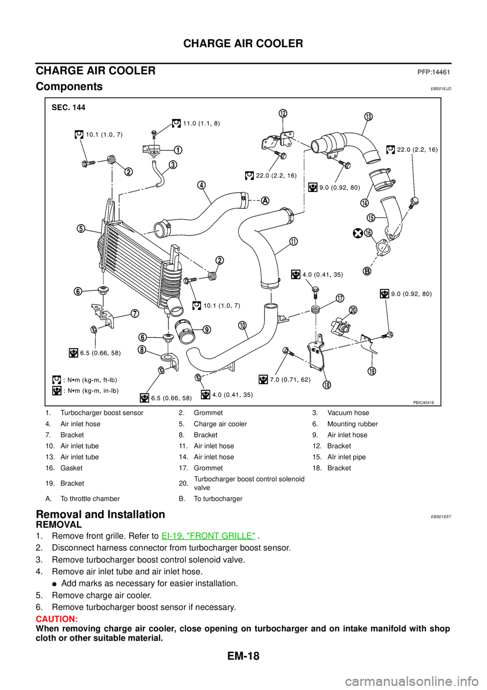
ComponentsEBS01EJD
Removal and InstallationEBS01E5T
REMOVAL
1. Remove front grille. Refer toEI-19, "FRONT GRILLE".
2. Disconnect harness connector from turbocharger boost sensor.
3. Remove turbocharger boost control solenoid valve.
4. Remove air inlet tube and air inlet hose.
lAdd marks as necessary for easier installation.
5. Remove charge air cooler.
6. Remove turbocharger boost sensor if necessary.
CAUTION:
When removing charge air cooler, close opening on turbocharger and on intake manifold with shop
cloth or other suitable material.
1. Turbocharger boost sensor 2. Grommet 3. Vacuum hose
4. Air inlet hose 5. Charge air cooler 6. Mounting rubber
7. Bracket 8. Bracket 9. Air inlet hose
10. Air inlet tube 11. Air inlet hose 12. Bracket
13. Air inlet tube 14. Air inlet hose 15. AIr inlet pipe
16. Gasket 17. Grommet 18. Bracket
19. Bracket 20.Turbocharger boost control solenoid
valve
A. To throttle chamber B. To turbocharger
PBIC4041E
Page 1418 of 3171
EM-36
OIL PAN AND OIL STRAINER
OIL PAN AND OIL STRAINER
P F P : 1111 0
ComponentsEBS01EJK
lRefer toGI-10, "Components"for symbol marks in the figure.
Removal and InstallationEBS01E5Z
REMOVAL
WARNING:
To avoid the danger of being scalded, do not drain engine oil when engine is hot.
1. Remove engine undercover front and engine undercover middle. Refer toEI-17, "
REAR BUMPER".
2. Drain engine oil. Refer toLU-6, "
Changing Engine Oil".
1. Oil level gauge 2. Oil level gauge guide 3. Oil level sensor
4. O-ring 5. O-ring 6. O-ring
7. Oil pan upper 8. Crankshaft position sensor 9. O-ring
10. Rear plate 11. Rear plate cover 12. Oil strainer
13. Oil pan drain plug 14. Drain plug washer 15. Oil pan lower
PBIC3424E
Page 1419 of 3171
OIL PAN AND OIL STRAINER
EM-37
C
D
E
F
G
H
I
J
K
L
MA
EM
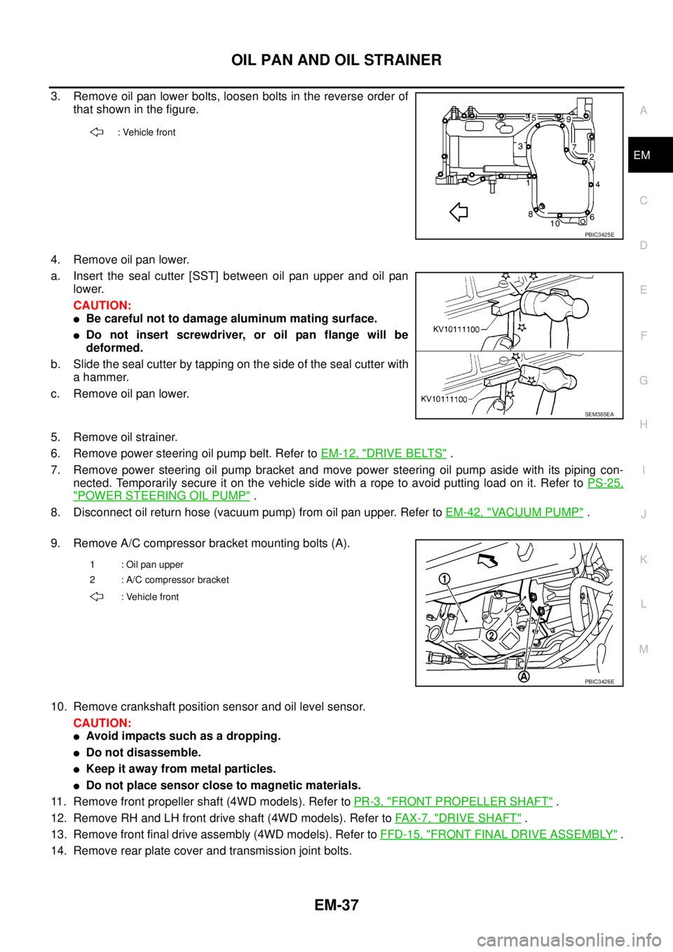
3. Remove oil pan lower bolts, loosen bolts in the reverse order of
that shown in the figure.
4. Remove oil pan lower.
a. Insert the seal cutter [SST] between oil pan upper and oil pan
lower.
CAUTION:
lBe careful not to damage aluminum mating surface.
lDo not insert screwdriver, or oil pan flange will be
deformed.
b. Slide the seal cutter by tapping on the side of the seal cutter with
a hammer.
c. Remove oil pan lower.
5. Remove oil strainer.
6. Remove power steering oil pump belt. Refer toEM-12, "
DRIVE BELTS".
7. Remove power steering oil pump bracket and move power steering oil pump aside with its piping con-
nected. Temporarily secure it on the vehicle side with a rope to avoid putting load on it. Refer toPS-25,
"POWER STEERING OIL PUMP".
8. Disconnect oil return hose (vacuum pump) from oil pan upper. Refer toEM-42, "
VACUUM PUMP".
9. Remove A/C compressor bracket mounting bolts (A).
10. Remove crankshaft position sensor and oil level sensor.
CAUTION:
lAvoid impacts such as a dropping.
lDo not disassemble.
lKeep it away from metal particles.
lDo not place sensor close to magnetic materials.
11. Remove front propeller shaft (4WD models). Refer toPR-3, "
FRONT PROPELLER SHAFT".
12. Remove RH and LH front drive shaft (4WD models). Refer toFAX-7, "
DRIVE SHAFT".
13. Remove front final drive assembly (4WD models). Refer toFFD-15, "
FRONT FINAL DRIVE ASSEMBLY".
14. Remove rear plate cover and transmission joint bolts.
: Vehicle front
PBIC3425E
SEM365EA
1 : Oil pan upper
2 : A/C compressor bracket
: Vehicle front
PBIC3426E
Page 1441 of 3171
CAMSHAFT
EM-59
C
D
E
F
G
H
I
J
K
L
MA
EM
CAMSHAFTPFP:13001
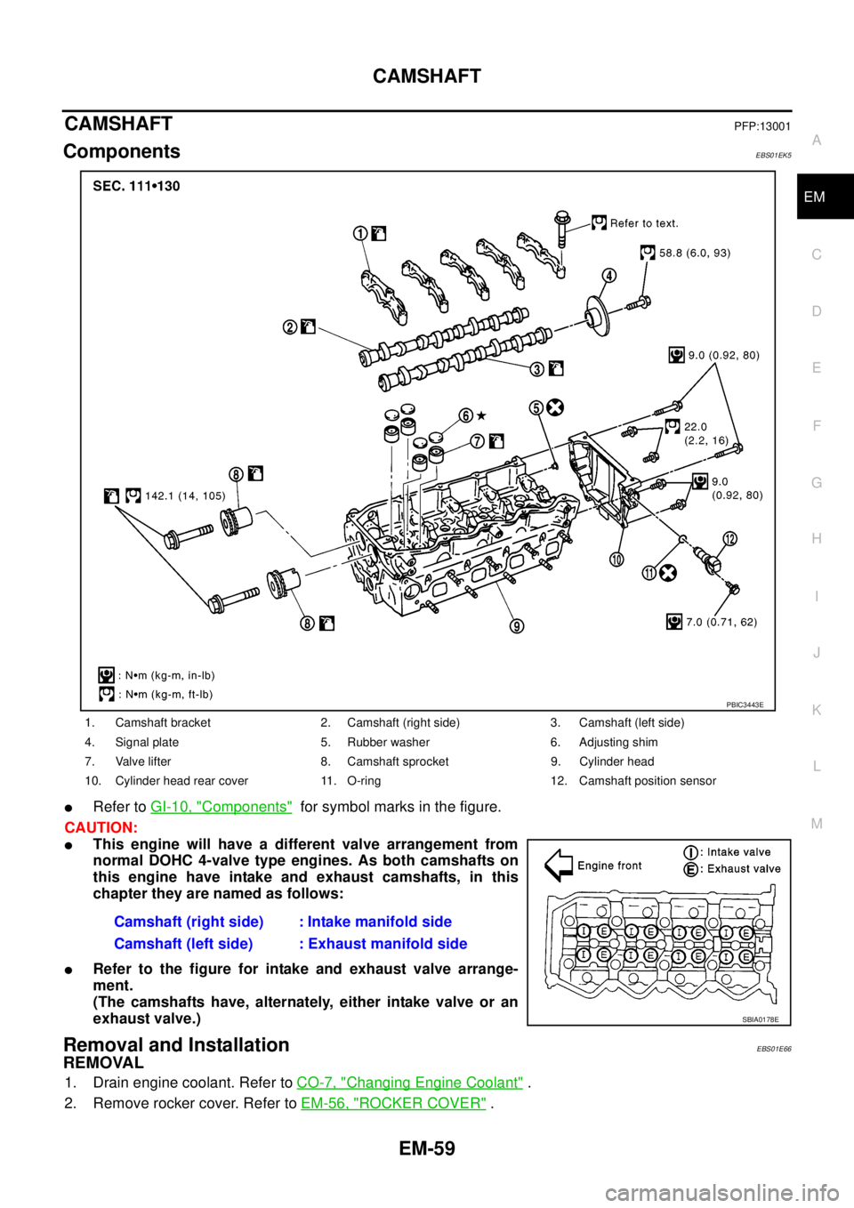
ComponentsEBS01EK5
lRefer toGI-10, "Components"for symbol marks in the figure.
CAUTION:
lThis engine will have a different valve arrangement from
normal DOHC 4-valve type engines. As both camshafts on
this engine have intake and exhaust camshafts, in this
chapter they are named as follows:
lRefer to the figure for intake and exhaust valve arrange-
ment.
(The camshafts have, alternately, either intake valve or an
exhaust valve.)
Removal and InstallationEBS01E66
REMOVAL
1. Drain engine coolant. Refer toCO-7, "Changing Engine Coolant".
2. Remove rocker cover. Refer toEM-56, "
ROCKER COVER".
1. Camshaft bracket 2. Camshaft (right side) 3. Camshaft (left side)
4. Signal plate 5. Rubber washer 6. Adjusting shim
7. Valve lifter 8. Camshaft sprocket 9. Cylinder head
10. Cylinder head rear cover 11. O-ring 12. Camshaft position sensor
Camshaft (right side) : Intake manifold side
Camshaft (left side) : Exhaust manifold side
PBIC3443E
SBIA0178E
Page 1442 of 3171
EM-60
CAMSHAFT
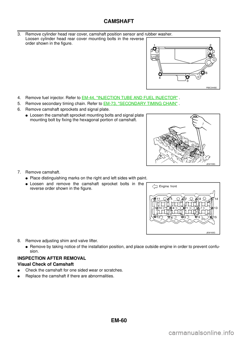
3. Remove cylinder head rear cover, camshaft position sensor and rubber washer.
Loosen cylinder head rear cover mounting bolts in the reverse
order shown in the figure.
4. Remove fuel injector. Refer toEM-44, "
INJECTION TUBE AND FUEL INJECTOR".
5. Remove secondary timing chain. Refer toEM-73, "
SECONDARY TIMING CHAIN".
6. Remove camshaft sprockets and signal plate.
lLoosen the camshaft sprocket mounting bolts and signal plate
mounting bolt by fixing the hexagonal portion of camshaft.
7. Remove camshaft.
lPlace distinguishing marks on the right and left sides with paint.
lLoosen and remove the camshaft sprocket bolts in the
reverse order shown in the figure.
8. Remove adjusting shim and valve lifter.
lRemove by taking notice of the installation position, and place outside engine in order to prevent confu-
sion.
INSPECTION AFTER REMOVAL
Visual Check of Camshaft
lCheck the camshaft for one sided wear or scratches.
lReplace the camshaft if there are abnormalities.
PBIC3445E
JEM159G
JEM160G