2005 NISSAN NAVARA sensor
[x] Cancel search: sensorPage 1305 of 3171
REFRIGERANT PRESSURE SENSOR
EC-325
C
D
E
F
G
H
I
J
K
L
MA
EC
REFRIGERANT PRESSURE SENSORPFP:92136
Component DescriptionEBS01KMG
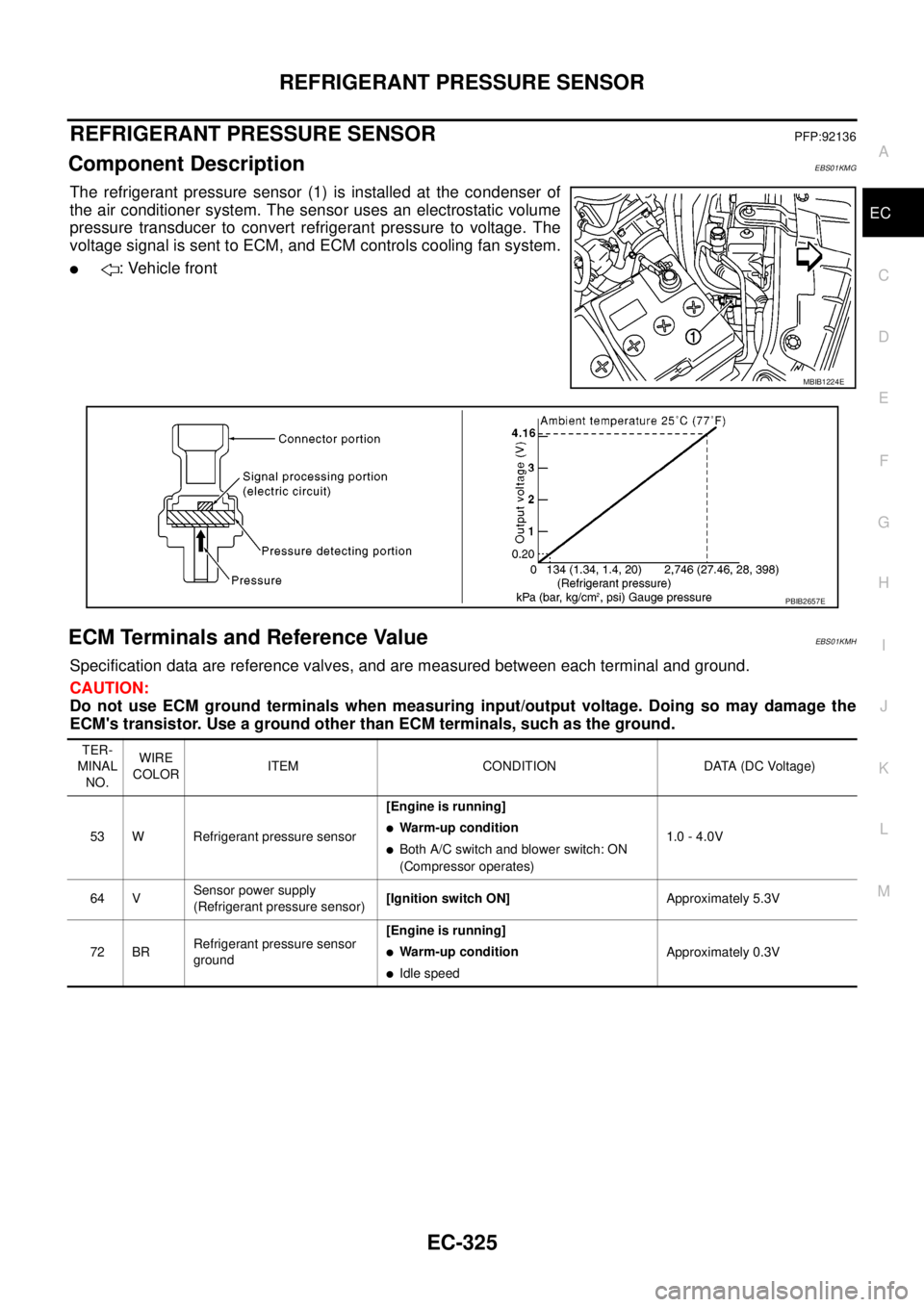
The refrigerant pressure sensor (1) is installed at the condenser of
the air conditioner system. The sensor uses an electrostatic volume
pressure transducer to convert refrigerant pressure to voltage. The
voltage signal is sent to ECM, and ECM controls cooling fan system.
l: Vehicle front
ECM Terminals and Reference ValueEBS01KMH
Specification data are reference valves, and are measured between each terminal and ground.
CAUTION:
Do not use ECM ground terminals when measuring input/output voltage. Doing so may damage the
ECM's transistor. Use a ground other than ECM terminals, such as the ground.
MBIB1224E
PBIB2657E
TER-
MINAL
NO.WIRE
COLORITEM CONDITION DATA (DC Voltage)
53 W Refrigerant pressure sensor[Engine is running]
lWarm-up condition
lBoth A/C switch and blower switch: ON
(Compressor operates)1.0 - 4.0V
64 VSensor power supply
(Refrigerant pressure sensor)[Ignition switch ON]Approximately 5.3V
72 BRRefrigerant pressure sensor
ground[Engine is running]
lWarm-up condition
lIdle speedApproximately 0.3V
Page 1306 of 3171
EC-326
REFRIGERANT PRESSURE SENSOR
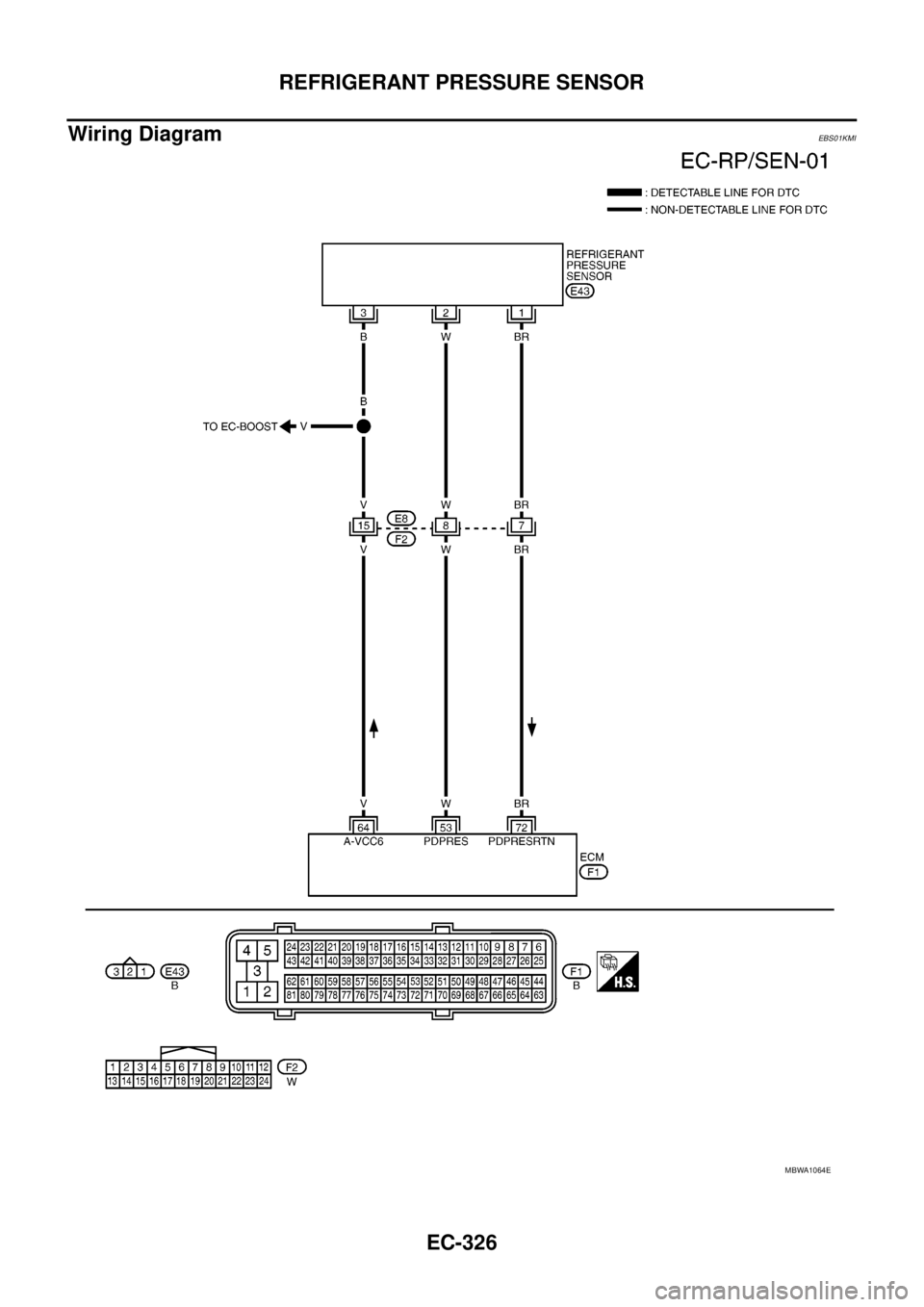
Wiring Diagram
EBS01KMI
MBWA1064E
Page 1307 of 3171
REFRIGERANT PRESSURE SENSOR
EC-327
C
D
E
F
G
H
I
J
K
L
MA
EC
Diagnostic ProcedureEBS01KMJ
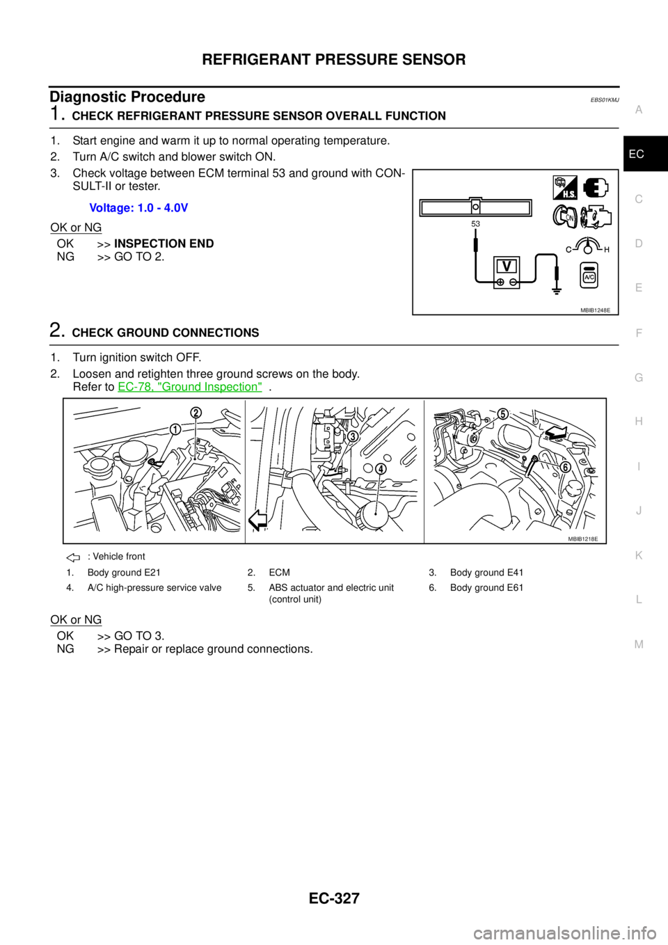
1.CHECK REFRIGERANT PRESSURE SENSOR OVERALL FUNCTION
1. Start engine and warm it up to normal operating temperature.
2. Turn A/C switch and blower switch ON.
3. Check voltage between ECM terminal 53 and ground with CON-
SULT-II or tester.
OK or NG
OK >>INSPECTION END
NG >> GO TO 2.
2.CHECK GROUND CONNECTIONS
1. Turn ignition switch OFF.
2. Loosen and retighten three ground screws on the body.
Refer toEC-78, "
Ground Inspection".
OK or NG
OK >> GO TO 3.
NG >> Repair or replace ground connections.Voltage: 1.0 - 4.0V
MBIB1248E
: Vehicle front
1. Body ground E21 2. ECM 3. Body ground E41
4. A/C high-pressure service valve 5. ABS actuator and electric unit
(control unit)6. Body ground E61
MBIB1218E
Page 1308 of 3171
EC-328
REFRIGERANT PRESSURE SENSOR
3.CHECK REFRIGERANT PRESSURE SENSOR POWER SUPPLY CIRCUIT
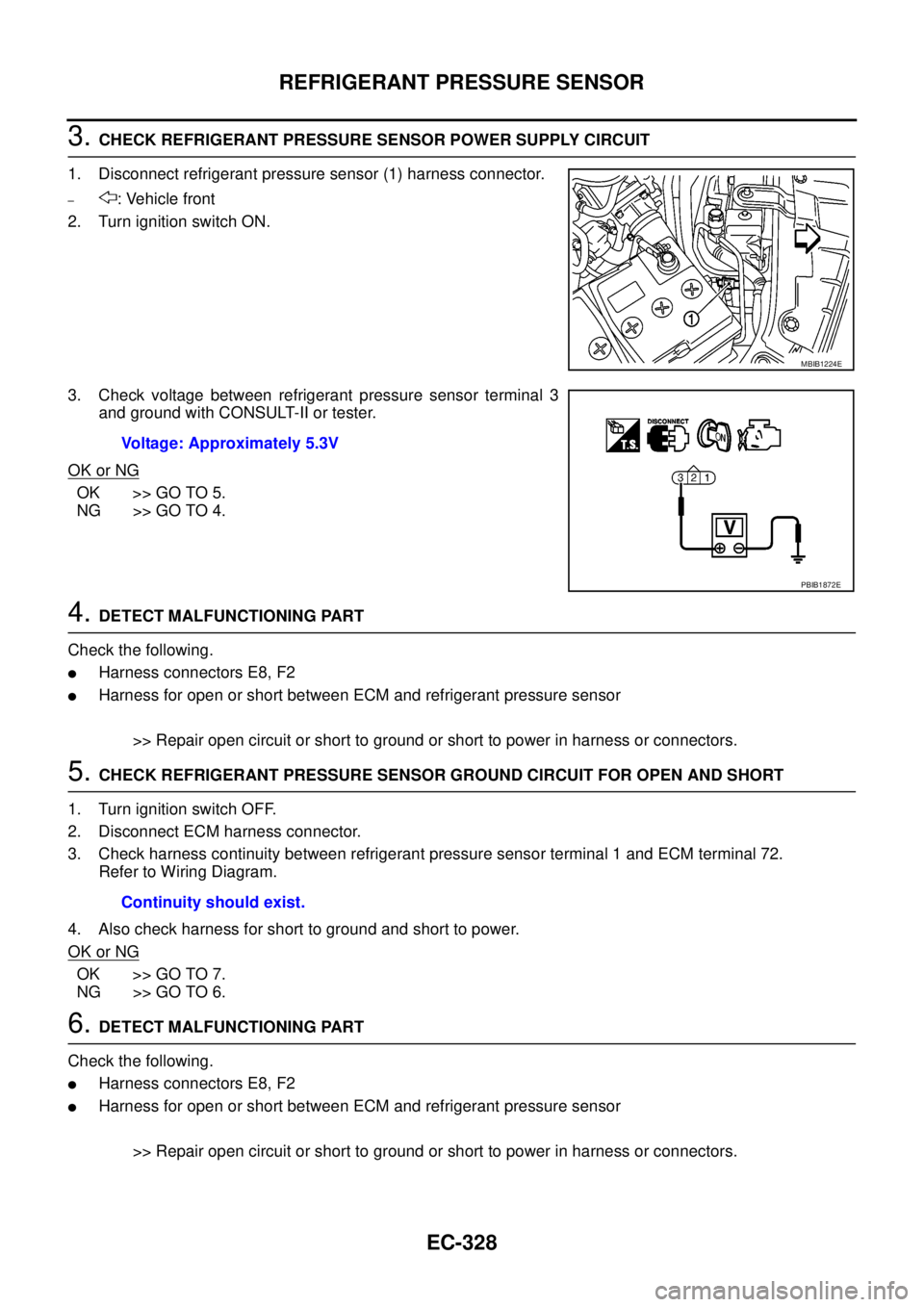
1. Disconnect refrigerant pressure sensor (1) harness connector.
–: Vehicle front
2. Turn ignition switch ON.
3. Check voltage between refrigerant pressure sensor terminal 3
and ground with CONSULT-II or tester.
OK or NG
OK >> GO TO 5.
NG >> GO TO 4.
4.DETECT MALFUNCTIONING PART
Check the following.
lHarness connectors E8, F2
lHarness for open or short between ECM and refrigerant pressure sensor
>> Repair open circuit or short to ground or short to power in harness or connectors.
5.CHECK REFRIGERANT PRESSURE SENSOR GROUND CIRCUIT FOR OPEN AND SHORT
1. Turn ignition switch OFF.
2. Disconnect ECM harness connector.
3. Check harness continuity between refrigerant pressure sensor terminal 1 and ECM terminal 72.
Refer to Wiring Diagram.
4. Also check harness for short to ground and short to power.
OK or NG
OK >> GO TO 7.
NG >> GO TO 6.
6.DETECT MALFUNCTIONING PART
Check the following.
lHarness connectors E8, F2
lHarness for open or short between ECM and refrigerant pressure sensor
>> Repair open circuit or short to ground or short to power in harness or connectors.
MBIB1224E
Voltage: Approximately 5.3V
PBIB1872E
Continuity should exist.
Page 1309 of 3171
REFRIGERANT PRESSURE SENSOR
EC-329
C
D
E
F
G
H
I
J
K
L
MA
EC
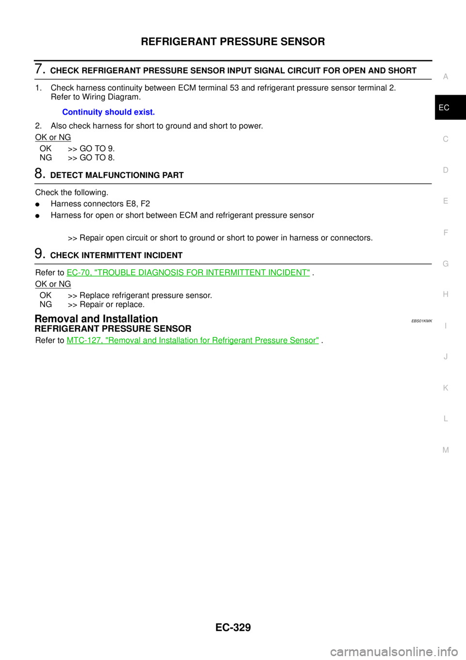
7.CHECK REFRIGERANT PRESSURE SENSOR INPUT SIGNAL CIRCUIT FOR OPEN AND SHORT
1. Check harness continuity between ECM terminal 53 and refrigerant pressure sensor terminal 2.
Refer to Wiring Diagram.
2. Also check harness for short to ground and short to power.
OK or NG
OK >> GO TO 9.
NG >> GO TO 8.
8.DETECT MALFUNCTIONING PART
Check the following.
lHarness connectors E8, F2
lHarness for open or short between ECM and refrigerant pressure sensor
>> Repair open circuit or short to ground or short to power in harness or connectors.
9.CHECK INTERMITTENT INCIDENT
Refer toEC-70, "
TROUBLE DIAGNOSIS FOR INTERMITTENT INCIDENT".
OK or NG
OK >> Replace refrigerant pressure sensor.
NG >> Repair or replace.
Removal and InstallationEBS01KMK
REFRIGERANT PRESSURE SENSOR
Refer toMTC-127, "Removal and Installation for Refrigerant Pressure Sensor". Continuity should exist.
Page 1335 of 3171

AUTOMATIC SPEED CONTROL DEVICE (ASCD)
EC-355
C
D
E
F
G
H
I
J
K
L
MA
EC
AUTOMATIC SPEED CONTROL DEVICE (ASCD)PFP:18930
System DescriptionEBS01KN2
INPUT/OUTPUT SIGNAL CHART
*: This signal is sent to the ECM through CAN communication line.
BASIC ASCD SYSTEM
Refer to Owner's Manual for ASCD operating instructions.
Automatic Speed Control Device (ASCD) allows a driver to keep vehicle at predetermined constant speed
without depressing accelerator pedal. Driver can set vehicle speed in advance between approximately 40 km/
h(25MPH)and185km/h(115MPH).
ECM controls fuel injection value to regulate engine speed.
Operation status of ASCD is indicated by CRUISE indicator and SET indicator in combination meter. If any
malfunction occurs in ASCD system, it automatically deactivates control.
SET OPERATION
Press ASCD MAIN switch. (The CRUISE indicator in combination meter illuminates.)
When vehicle speed reaches a desired speed between approximately 40 km/h (25 MPH) and 185 km/h (115
MPH), press SET/COST switch. (Then SET indicator in combination meter illuminates.)
ACCEL OPERATION
If the RESUME/ACCELERATE switch is depressed during cruise control driving, increase the vehicle speed
until the switch is released or vehicle speed reaches maximum speed controlled by the system.
And then ASCD will keep the new set speed.
CANCEL OPERATION
When any of following conditions exist, cruise operation will be canceled.
lCANCEL switch is depressed
lMore than 2 switches at ASCD steering switch are depressed at the same time (Set speed will be cleared)
lBrake pedal is depressed
lClutch pedal is depressed or gear position is changed to the neutral position (M/T models)
lSelector lever is changed to N, P, R position (A/T models)
lVehicle speed decreased to 13 km/h (8 MPH) lower than the set speed
When the ECM detects any of the following conditions, the ECM will cancel the cruise operation and inform
the driver by blinking indicator lamp.
lMalfunction for some self-diagnoses regarding ASCD control: SET lamp will blink quickly.
If MAIN switch is turned to OFF during ASCD is activated, all of ASCD operations will be canceled and vehicle
speed memory will be erased.
COAST OPERATION
When the SET/COAST switch is depressed during cruise control driving, decrease vehicle set speed until the
switch is released. And then ASCD will keep the new set speed.
RESUME OPERATION
When the RESUME/ACCELERATE switch is depressed after cancel operation other than depressing MAIN
switch is performed, vehicle speed will return to last set speed. To resume vehicle set speed, vehicle condition
must meet following conditions.
Sensor Input signal to ECM ECM function Actuator
ASCD brake switch Brake pedal operation
ASCD vehicle speed control Fuel injector and Fuel pump Stop lamp switch Brake pedal operation
ASCD clutch switch (M/T) Clutch pedal operation
ASCD steering switch ASCD steering switch operation
Park/Neutral position (PNP)
switchGear position
Combination meter* Vehicle speed
TCM* Powertrain revolution
Page 1337 of 3171

SERVICE DATA AND SPECIFICATIONS (SDS)
EC-357
C
D
E
F
G
H
I
J
K
L
MA
EC
SERVICE DATA AND SPECIFICATIONS (SDS)PFP:00100
General SpecificationsEBS01KN4
*: Under the following conditions:
lHeat up switch: OFF
lAir conditioner switch: OFF
lElectric load: OFF (Lights, heater fan & rear window defogger)
lSteering wheel: Kept in straight-ahead position
Mass Air Flow SensorEBS01KN5
*: Engine is warmed up to normal operating temperature and running under no load.
Intake Air Temperature SensorEBS01KN6
Engine Coolant Temperature SensorEBS01KN7
Fuel Rail Pressure SensorEBS01KN8
Fuel InjectorEBS01KN9
Glow PlugEBS01KNA
EGR Volume Control ValveEBS01KNB
Crankshaft Position SensorEBS01KNC
Refer toEC-164, "Component Inspection".
Camshaft Position SensorEBS01KND
Refer toEC-175, "Component Inspection".
Target idle speedA/T No load* (in P or N position)
750±25 rpm
M/T No load* (in Neutral position)
Air conditioner: ONA/T In P or N position 750 rpm or more
M/T In Neutral position 800 rpm or more
Maximum engine speed4,900 rpm
Supply voltageBattery voltage (11 - 14V)
Ignition switch ON (Engine stopped.) Approx. 0.4V
Idle (Engine is warmed up to normal operating temperature.) 1.3 - 1.7V *
Temperature°C(°F) Resistance kW
25 (77)1.800 - 2.200
80 (176)0.283 - 0.359
Temperature°C(°F) Resistance kW
20 (68)2.1 - 2.9
50 (122)0.68 - 1.00
90 (194)0.236 - 0.260
Supply voltageApproximately 5V
Idle (Engine is warmed up to normal operating temperature.) 1.7 - 2.0V
2,000 rpm (Engine is warmed up to normal operating tempera-
ture.)2.0 - 2.3V
Resistance [at 10 - 60°C (50 - 140°F)] 0.2 - 0.8W
Resistance [at 25°C(77°F)] Approximately 0.8W
Resistance [at 25°C(77°F)] 13 - 17W
Page 1341 of 3171

PRECAUTIONS
EI-3
C
D
E
F
G
H
J
K
L
MA
B
EI
PRECAUTIONSPFP:00001
Service NoticeEIS00DY1
lWhen removing or installing various parts, place a cloth or padding on the vehicle body to prevent
scratches.
lHandle trim, molding, instruments, grille, etc. carefully during removing or installing. Be careful not to soil
or damage them.
lApply sealing compound where necessary when installing parts.
lWhen applying sealing compound, be careful that the sealing compound does not protrude from parts.
lWhen replacing any metal parts (for example body outer panel, members, etc.), be sure to take rust pre-
vention measures.
Precautions for Supplemental Restraint System (SRS) “AIR BAG” and “SEAT
BELT PRE-TENSIONER”
EIS00DZ5
The Supplemental Restraint System such as “AIR BAG” and “SEAT BELT PRE-TENSIONER”, used along
with a front seat belt, helps to reduce the risk or severity of injury to the driver and front passenger for certain
types of collision. Information necessary to service the system safely is included in the SRS and SB section of
this Service Manual.
WARNING:
lTo avoid rendering the SRS inoperative, which could increase the risk of personal injury or death
in the event of a collision which would result in air bag inflation, all maintenance must be per-
formed by an authorized NISSAN/INFINITI dealer.
lImproper maintenance, including incorrect removal and installation of the SRS, can lead to per-
sonal injury caused by unintentional activation of the system. For removal of Spiral Cable and Air
Bag Module, see the SRS section.
lDo not use electrical test equipment on any circuit related to the SRS unless instructed to in this
Service Manual. SRS wiring harnesses can be identified by yellow and/or orange harnesses or
harness connectors.
Precautions for SRS “AIR BAG” and “SEAT BELT PRE-TENSIONER” ServiceEIS00DZ2
lDo not use electrical test equipment to check SRS circuits unless instructed to in this Service Manual.
lBefore servicing the SRS, turn ignition switch OFF, disconnect both battery cables and wait at least 3 min-
utes.
For approximately 3 minutes after the cables are removed, it is still possible for the air bag and seat belt
pre-tensioner to deploy. Therefore, do not work on any SRS connectors or wires until at least 3 minutes
have passed.
lThe air bag diagnosis sensor unit must always be installed with the arrow marks “Ü” pointing toward the
front of the vehicle for proper operation. Also check the air bag diagnosis sensor unit for cracks, deformi-
ties or rust before installation and replace as required.
lThe spiral cable must be aligned with the neutral position since its rotations are limited. Do not attempt to
turn steering wheel or column after removal of steering gear.
lHandle air bag module carefully. Always place driver and front passenger air bag modules with the pad
side facing upward and seat mounted front side air bag module standing with the stud bolt side facing
down.
lConduct self-diagnosis to check entire SRS for proper function after replacing any components.
lAfter air bag inflates, the front instrument panel assembly should be replaced if damaged.