Page 1259 of 3171
DTC P2135 APP SENSOR
EC-279
C
D
E
F
G
H
I
J
K
L
MA
EC
3.CHECK APP SENSOR GROUND CIRCUIT FOR OPEN AND SHORT
1. Turn ignition switch OFF.
2. Disconnect ECM harness connector.
3. Check harness continuity between APP sensor terminal 4 and ECM terminal 84, APP sensor terminal 5
and ECM terminal 92.
Refer to Wiring Diagram.
4. Also check harness for short to ground and short to power.
OK or NG
OK >> GO TO 4.
NG >> Repair open circuit or short to ground or short to power in harness or connectors.
4.CHECK APP SENSOR INPUT SIGNAL CIRCUIT FOR OPEN AND SHORT
1. Check harness continuity between ECM terminal 83 and APP sensor terminal 3, ECM terminal 91 and
APPsensorterminal6.
Refer to Wiring Diagram.
2. Also check harness for short to ground and short to power.
OK or NG
OK >> GO TO 5.
NG >> Repair open circuit or short to ground or short to power in harness or connectors.
5.CHECK APP SENSOR
Refer toEC-279, "
Component Inspection".
OK or NG
OK >> GO TO 6.
NG >> Replace accelerator pedal assembly.
6.CHECK INTERMITTENT INCIDENT
Refer toEC-70, "
TROUBLE DIAGNOSIS FOR INTERMITTENT INCIDENT".
>>INSPECTION END
Component InspectionEBS01KL0
ACCELERATOR PEDAL POSITION SENSOR
1. Reconnect all harness connectors disconnected.
2. Turn ignition switch ON.
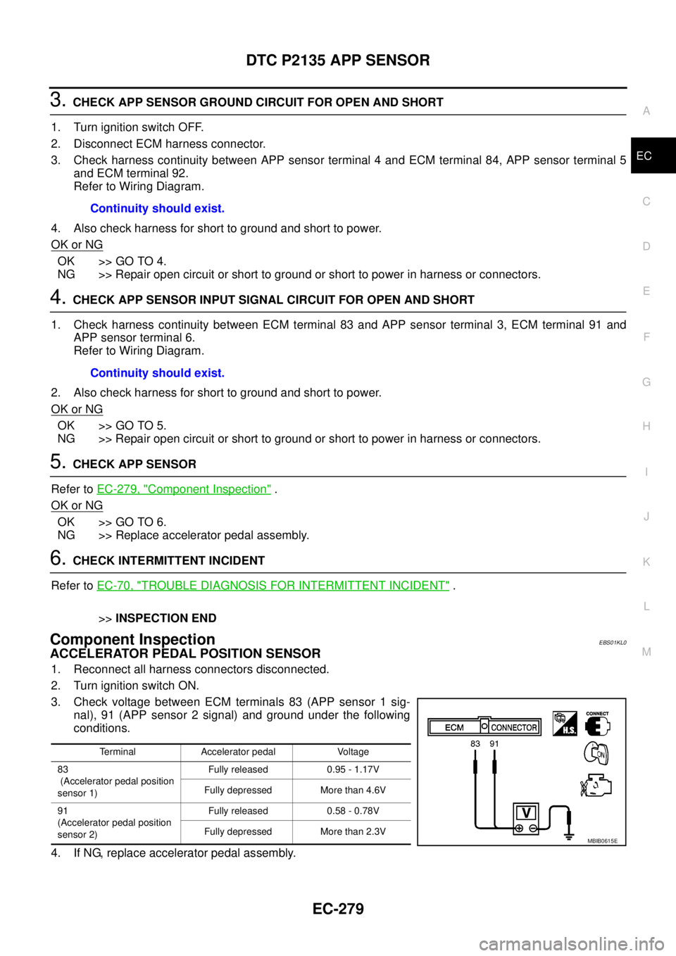
3. Check voltage between ECM terminals 83 (APP sensor 1 sig-
nal), 91 (APP sensor 2 signal) and ground under the following
conditions.
4. If NG, replace accelerator pedal assembly.Continuity should exist.
Continuity should exist.
Terminal Accelerator pedal Voltage
83
(Accelerator pedal position
sensor 1)Fully released 0.95 - 1.17V
Fully depressed More than 4.6V
91
(Accelerator pedal position
sensor 2)Fully released 0.58 - 0.78V
Fully depressed More than 2.3V
MBIB0615E
Page 1260 of 3171
EC-280
DTC P2135 APP SENSOR
Removal and Installation
EBS01KL1
ACCELERATOR PEDAL
Refer toACC-2, "ACCELERATOR CONTROL SYSTEM".
Page 1273 of 3171
DTC P2228, P2229 BARO SENSOR
EC-293
C
D
E
F
G
H
I
J
K
L
MA
EC
DTC P2228, P2229 BARO SENSORPFP:23731
DescriptionEBS01KLI
The barometric pressure sensor is built into ECM. The sensor
detects ambient barometric pressure and sends the voltage signal to
the microcomputer.
On Board Diagnosis LogicEBS01KLJ
The MI will not light up for these self-diagnoses.
DTC Confirmation ProcedureEBS01KLK
NOTE:
If DTC Confirmation Procedure has been previously conducted, always turn ignition switch OFF and wait at
least 10 seconds before conducting the next test.
WITH CONSULT-II
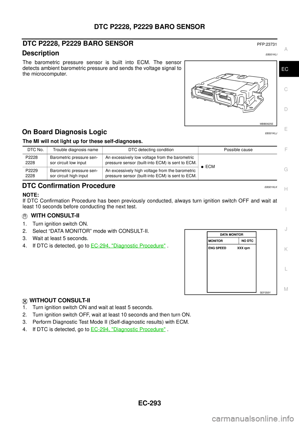
1. Turn ignition switch ON.
2. Select “DATA MONITOR” mode with CONSULT-II.
3. Wait at least 5 seconds.
4. If DTC is detected, go toEC-294, "
Diagnostic Procedure".
WITHOUT CONSULT-II
1. Turn ignition switch ON and wait at least 5 seconds.
2. Turn ignition switch OFF, wait at least 10 seconds and then turn ON.
3. Perform Diagnostic Test Mode II (Self-diagnostic results) with ECM.
4. If DTC is detected, go toEC-294, "
Diagnostic Procedure".
MBIB0625E
DTC No. Trouble diagnosis name DTC detecting condition Possible cause
P2228
2228Barometric pressure sen-
sor circuit low inputAn excessively low voltage from the barometric
pressure sensor (built-into ECM) is sent to ECM.
lECM
P2229
2228Barometric pressure sen-
sor circuit high inputAn excessively high voltage from the barometric
pressure sensor (built-into ECM) is sent to ECM.
SEF058Y
Page 1274 of 3171
EC-294
DTC P2228, P2229 BARO SENSOR
Diagnostic Procedure
EBS01KLL
1.INSPECTION START
With CONSULT-II
1. Turn ignition switch ON.
2. Select “SELF DIAG RESULTS” mode with CONSULT-II.
3. Touch “ERASE”.
4. PerformEC-293, "
DTC Confirmation Procedure",again.
5. Is DTC P2228 or P2229 displayed again?
Without CONSULT-II
1. Turn ignition switch ON.
2. Erase the Diagnostic Test Mode II (Self-diagnostic results) memory. Refer toEC-27
.
3. PerformEC-293, "
DTC Confirmation Procedure",again.
4. Is DTC 2228 or 2229 displayed again?
Ye s o r N o
Yes >>GOTO2.
No >>INSPECTION END
2.REPLACE ECM
1. Replace ECM.
2. Perform initialization of NATS system and registration of all NATS ignition key IDs. Refer toBL-172, "
ECM
Re-communicating Function".
3. Perform Fuel Pump Learning Valve Clearing. Refer toEC-24, "
Fuel Pump Learning Value Clearing".
4. Perform Injector Adjustment Value Registration. Refer toEC-25, "
Injector Adjustment Value Registration".
>>INSPECTION END
Page 1275 of 3171
GLOW CONTROL SYSTEM
EC-295
C
D
E
F
G
H
I
J
K
L
MA
EC
GLOW CONTROL SYSTEMPFP:25230
DescriptionEBS01KLM
SYSTEM DESCRIPTION
*: The output signal is sent from the ECM through CAN communication line.
When engine coolant temperature is more than approximately 80°C(176°F), the glow relay turns off.
When engine coolant temperature is lower than approximately 80°C(176°F):
lIgnition switch ON
After ignition switch has turned to ON, the glow relay turns ON for a certain period of time in relation to
engine coolant temperature, allowing current to flow through glow plug.
lCranking
The glow relay turns ON, allowing current to flow through glow plug.
lSta rti ng
After engine has started, current continues to flow through glow plug (after-glow mode) for a certain period
in relation to engine coolant temperature.
The glow indicator lamp turns ON for a certain period of time in relation to engine coolant temperature at the
time glow relay is turned ON.
COMPONENT DESCRIPTION
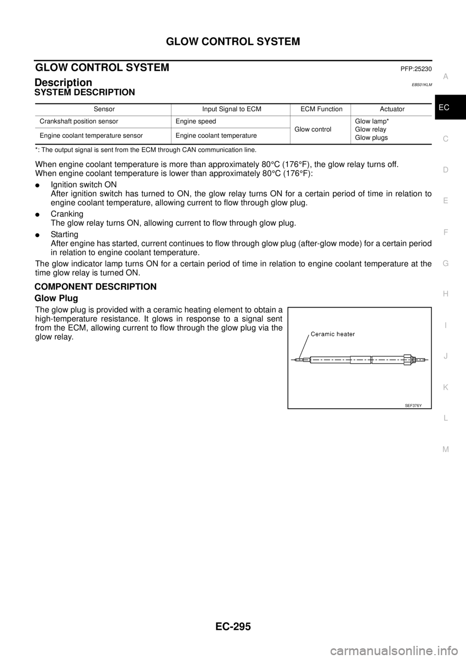
Glow Plug
The glow plug is provided with a ceramic heating element to obtain a
high-temperature resistance. It glows in response to a signal sent
from the ECM, allowing current to flow through the glow plug via the
glow relay.
Sensor Input Signal to ECM ECM Function Actuator
Crankshaft position sensor Engine speed
Glow controlGlow lamp*
Glow relay
Glow plugs Engine coolant temperature sensor Engine coolant temperature
SEF376Y
Page 1277 of 3171
GLOW CONTROL SYSTEM
EC-297
C
D
E
F
G
H
I
J
K
L
MA
EC
Diagnostic ProcedureEBS01KLO
1.INSPECTION START
Check fuel level, fuel supplying system, starter motor, etc.
OK or NG
OK >> GO TO 2.
NG >> Correct.
2.CHECK INSTALLATION
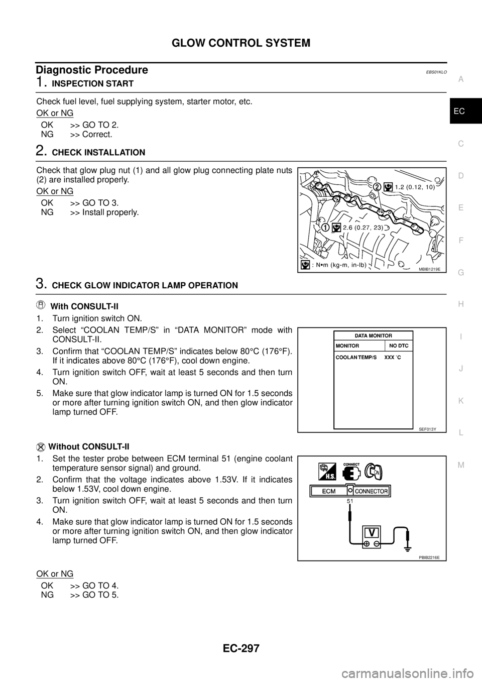
Check that glow plug nut (1) and all glow plug connecting plate nuts
(2) are installed properly.
OK or NG
OK >> GO TO 3.
NG >> Install properly.
3.CHECK GLOW INDICATOR LAMP OPERATION
With CONSULT-II
1. Turn ignition switch ON.
2. Select “COOLAN TEMP/S” in “DATA MONITOR” mode with
CONSULT-II.
3. Confirm that “COOLAN TEMP/S” indicates below 80°C(176°F).
If it indicates above 80°C(176°F), cool down engine.
4. Turn ignition switch OFF, wait at least 5 seconds and then turn
ON.
5. Make sure that glow indicator lamp is turned ON for 1.5 seconds
or more after turning ignition switch ON, and then glow indicator
lamp turned OFF.
Without CONSULT-II
1. Set the tester probe between ECM terminal 51 (engine coolant
temperature sensor signal) and ground.
2. Confirm that the voltage indicates above 1.53V. If it indicates
below 1.53V, cool down engine.
3. Turn ignition switch OFF, wait at least 5 seconds and then turn
ON.
4. Make sure that glow indicator lamp is turned ON for 1.5 seconds
or more after turning ignition switch ON, and then glow indicator
lamp turned OFF.
OK or NG
OK >> GO TO 4.
NG >> GO TO 5.
MBIB1219E
SEF013Y
PBIB2216E
Page 1278 of 3171
EC-298
GLOW CONTROL SYSTEM
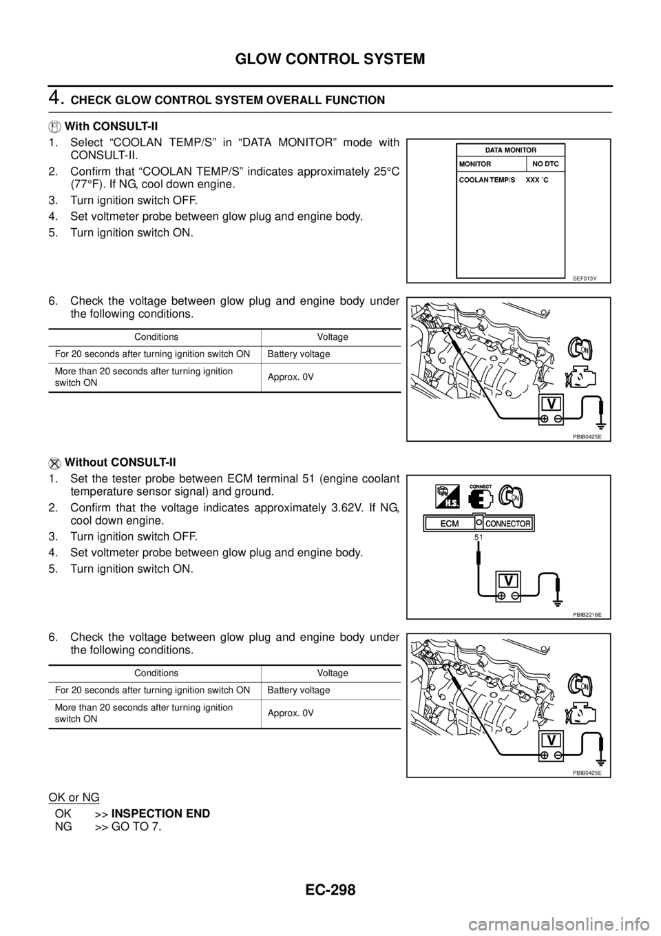
4.CHECK GLOW CONTROL SYSTEM OVERALL FUNCTION
With CONSULT-II
1. Select “COOLAN TEMP/S” in “DATA MONITOR” mode with
CONSULT-II.
2. Confirm that “COOLAN TEMP/S” indicates approximately 25°C
(77°F). If NG, cool down engine.
3. Turn ignition switch OFF.
4. Set voltmeter probe between glow plug and engine body.
5. Turn ignition switch ON.
6. Check the voltage between glow plug and engine body under
the following conditions.
Without CONSULT-II
1. Set the tester probe between ECM terminal 51 (engine coolant
temperature sensor signal) and ground.
2. Confirm that the voltage indicates approximately 3.62V. If NG,
cool down engine.
3. Turn ignition switch OFF.
4. Set voltmeter probe between glow plug and engine body.
5. Turn ignition switch ON.
6. Check the voltage between glow plug and engine body under
the following conditions.
OK or NG
OK >>INSPECTION END
NG >> GO TO 7.
SEF013Y
Conditions Voltage
For 20 seconds after turning ignition switch ON Battery voltage
More than 20 seconds after turning ignition
switch ONApprox. 0V
PBIB0425E
PBIB2216E
Conditions Voltage
For 20 seconds after turning ignition switch ON Battery voltage
More than 20 seconds after turning ignition
switch ONApprox. 0V
PBIB0425E
Page 1282 of 3171
EC-302
EGR VOLUME CONTROL SYSTEM
EGR VOLUME CONTROL SYSTEM
PFP:14710
DescriptionEBS01KLR
SYSTEM DESCRIPTION
*: This signal is sent to the ECM through CAN communication line.
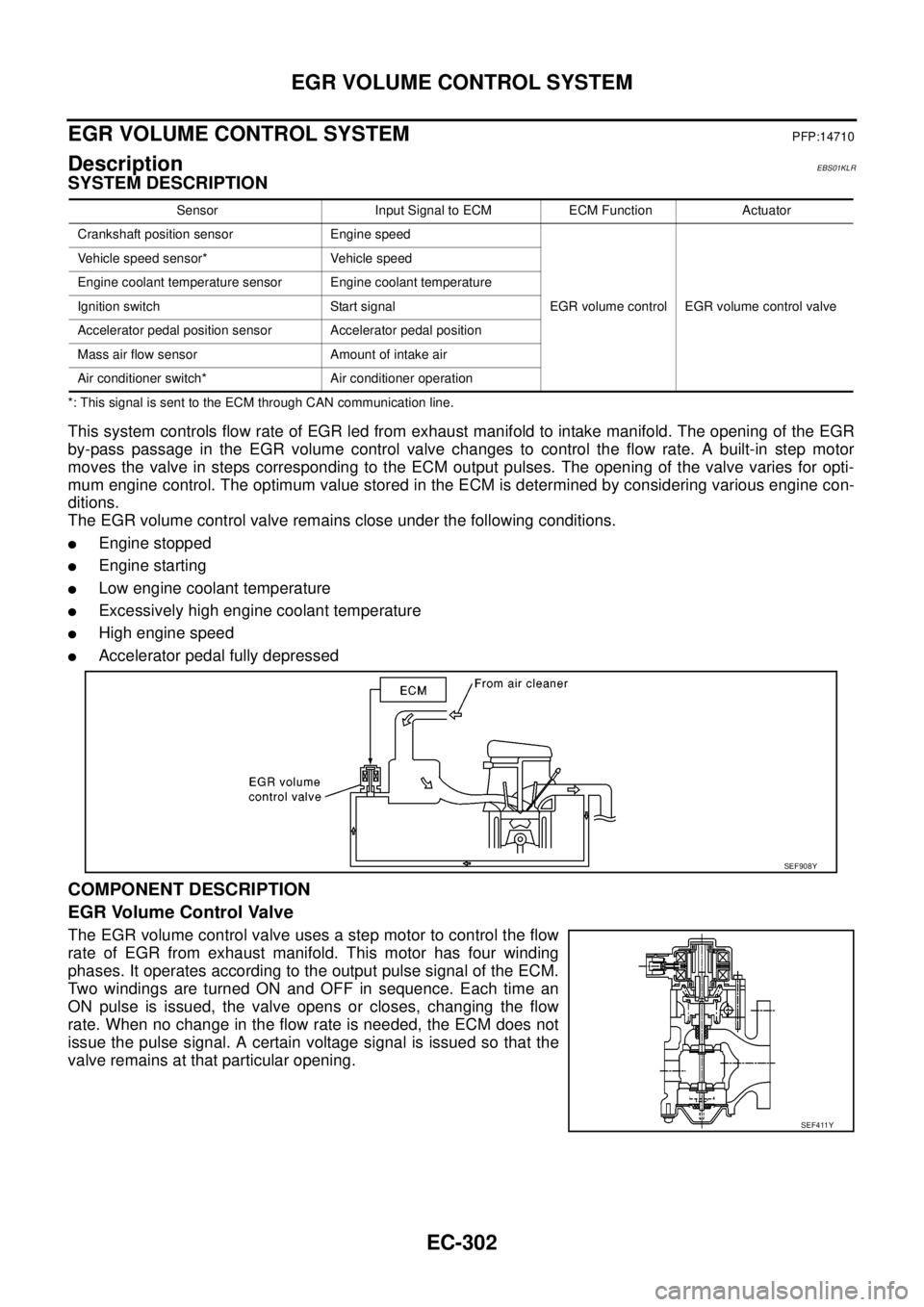
This system controls flow rate of EGR led from exhaust manifold to intake manifold. The opening of the EGR
by-pass passage in the EGR volume control valve changes to control the flow rate. A built-in step motor
moves the valve in steps corresponding to the ECM output pulses. The opening of the valve varies for opti-
mum engine control. The optimum value stored in the ECM is determined by considering various engine con-
ditions.
The EGR volume control valve remains close under the following conditions.
lEngine stopped
lEngine starting
lLow engine coolant temperature
lExcessively high engine coolant temperature
lHigh engine speed
lAccelerator pedal fully depressed
COMPONENT DESCRIPTION
EGR Volume Control Valve
The EGR volume control valve uses a step motor to control the flow
rate of EGR from exhaust manifold. This motor has four winding
phases. It operates according to the output pulse signal of the ECM.
Two windings are turned ON and OFF in sequence. Each time an
ON pulse is issued, the valve opens or closes, changing the flow
rate. When no change in the flow rate is needed, the ECM does not
issue the pulse signal. A certain voltage signal is issued so that the
valve remains at that particular opening.
Sensor Input Signal to ECM ECM Function Actuator
Crankshaft position sensor Engine speed
EGR volume control EGR volume control valve Vehicle speed sensor* Vehicle speed
Engine coolant temperature sensor Engine coolant temperature
Ignition switch Start signal
Accelerator pedal position sensor Accelerator pedal position
Mass air flow sensor Amount of intake air
Air conditioner switch* Air conditioner operation
SEF908Y
SEF411Y