Page 446 of 3171

ATC-112
TROUBLE DIAGNOSIS
Optical Sensor Circuit
EJS006BY
COMPONENT DESCRIPTION
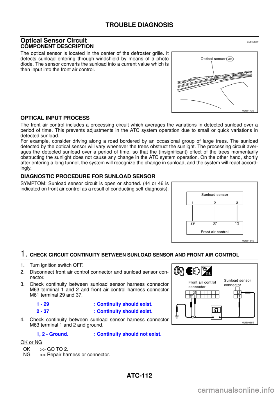
The optical sensor is located in the center of the defroster grille. It
detects sunload entering through windshield by means of a photo
diode. The sensor converts the sunload into a current value which is
then input into the front air control.
OPTICAL INPUT PROCESS
The front air control includes a processing circuit which averages the variations in detected sunload over a
period of time. This prevents adjustments in the ATC system operation due to small or quick variations in
detected sunload.
For example, consider driving along a road bordered by an occasional group of large trees. The sunload
detected by the optical sensor will vary whenever the trees obstruct the sunlight. The processing circuit aver-
ages the detected sunload over a period of time, so that the (insignificant) effect of the trees momentarily
obstructing the sunlight does not cause any change in the ATC system operation. On the other hand, shortly
after entering a long tunnel, the system will recognize the change in sunload, and the system will react accord-
ingly.
DIAGNOSTIC PROCEDURE FOR SUNLOAD SENSOR
SYMPTOM: Sunload sensor circuit is open or shorted. (44 or 46 is
indicated on front air control as a result of conducting self-diagnosis).
1.CHECK CIRCUIT CONTINUITY BETWEEN SUNLOAD SENSOR AND FRONT AIR CONTROL
1. Turn ignition switch OFF.
2. Disconnect front air control connector and sunload sensor con-
nector.
3. Check continuity between sunload sensor harness connector
M63 terminal 1 and 2 and front air control harness connector
M61 terminal 29 and 37.
4. Check continuity between sunload sensor harness connector
M63 terminal 1 and 2 and ground.
OK or NG
OK >> GO TO 2.
NG >> Repair harness or connector.
MJIB0172E
MJIB0181E
1 - 29 : Continuity should exist.
2 - 37 : Continuity should exist.
1, 2 - Ground. : Continuity should not exist.
MJIB0086E
Page 447 of 3171
TROUBLE DIAGNOSIS
ATC-113
C
D
E
F
G
H
I
K
L
MA
B
AT C
2.CHECK CIRCUIT CONTINUITY BETWEEN SUNLOAD SENSOR AND FRONT AIR CONTROL
1. Turn ignition switch OFF.
2. Disconnect front air control connector and sunload sensor con-
nector.
3. Check continuity between sunload sensor harness connector
M63 terminal 3 and front air control harness connector M60 ter-
minal 13.
4. Check continuity between sunload sensor harness connector
M63 terminal 3 and ground.
OK or NG
OK >> Replace sunload sensor.
NG >> Repair harness or connector.3 - 13 : Continuity should exist.
3 - Ground : Continuity should not exist.
MJIB0087E
Page 448 of 3171

ATC-114
TROUBLE DIAGNOSIS
Intake Sensor Circuit
EJS006BZ
COMPONENT DESCRIPTION
Intake Sensor
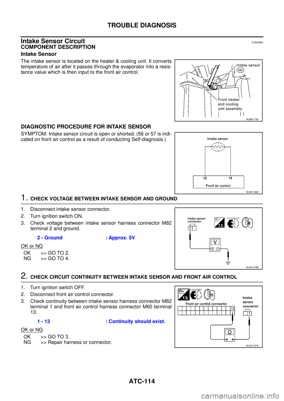
The intake sensor is located on the heater & cooling unit. It converts
temperature of air after it passes through the evaporator into a resis-
tance value which is then input to the front air control.
DIAGNOSTIC PROCEDURE FOR INTAKE SENSOR
SYMPTOM: Intake sensor circuit is open or shorted. (56 or 57 is indi-
cated on front air control as a result of conducting Self-diagnosis.)
1.CHECK VOLTAGE BETWEEN INTAKE SENSOR AND GROUND
1. Disconnect intake sensor connector.
2. Turn ignition switch ON.
3. Check voltage between intake sensor harness connector M82
terminal 2 and ground.
OK or NG
OK >> GO TO 2.
NG >> GO TO 4.
2.CHECK CIRCUIT CONTINUITY BETWEEN INTAKE SENSOR AND FRONT AIR CONTROL
1. Turn ignition switch OFF.
2. Disconnect front air control connector.
3. Check continuity between intake sensor harness connector M82
terminal 1 and front air control harness connector M60 terminal
13.
OK or NG
OK >> GO TO 3.
NG >> Repair harness or connector.
MJIB0173E
WJIA1156E
2 - Ground : Approx. 5V
WJIA1278E
1 - 13 : Continuity should exist.
WJIA1157E
Page 449 of 3171

TROUBLE DIAGNOSIS
ATC-115
C
D
E
F
G
H
I
K
L
MA
B
AT C
3.CHECK INTAKE SENSOR
Refer toAT C - 11 5 , "
Intake Sensor".
OK or NG
OK >> 1. Replace front air control.
2. Go to self-diagnosisAT C - 5 5 , "
A/C System Self-diagnosis Function"and perform self-diagno-
sis.
NG >> 1. Replace intake sensor.
2. Go to self-diagnosisAT C - 5 5 , "
A/C System Self-diagnosis Function"and perform self-diagno-
sis.
4.CHECK CIRCUIT CONTINUITY BETWEEN INTAKE SENSOR AND FRONT AIR CONTROL
1. Turn ignition switch OFF.
2. Disconnect front air control connector.
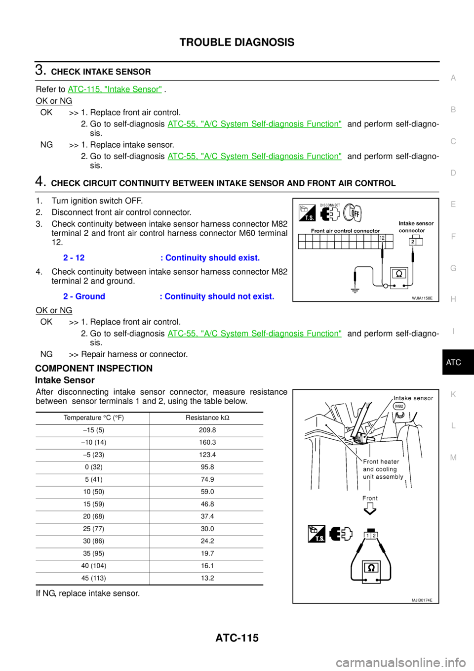
3. Check continuity between intake sensor harness connector M82
terminal 2 and front air control harness connector M60 terminal
12.
4. Check continuity between intake sensor harness connector M82
terminal 2 and ground.
OK or NG
OK >> 1. Replace front air control.
2. Go to self-diagnosisAT C - 5 5 , "
A/C System Self-diagnosis Function"and perform self-diagno-
sis.
NG >> Repair harness or connector.
COMPONENT INSPECTION
Intake Sensor
After disconnecting intake sensor connector, measure resistance
between sensor terminals 1 and 2, using the table below.
If NG, replace intake sensor.2 - 12 : Continuity should exist.
2 - Ground : Continuity should not exist.
WJIA1158E
Temperature°C(°F) Resistance kW
-15 (5) 209.8
-10 (14) 160.3
-5 (23) 123.4
0 (32) 95.8
5 (41) 74.9
10 (50) 59.0
15 (59) 46.8
20 (68) 37.4
25 (77) 30.0
30 (86) 24.2
35 (95) 19.7
40 (104) 16.1
45 (113) 13.2
MJIB0174E
Page 493 of 3171

SYSTEM DESCRIPTION
AV-5
C
D
E
F
G
H
I
J
L
MA
B
AV
Personal Audio Setting
The radio is designed to store several settings (volume, bass, treble, preset stations) with every NATS ignition
key used. Up to a maximum of 4 NATS keys can be registered. During the communication mentioned under
“Anti-Theft System”, the radio will recognize the used ignition key and select the accompanying settings.
VEHICLE INFORMATION SYSTEM
lThe status of audio system, fuel consumption, rear view monitor and navigation system are displayed.
lNAVI control unit receives the data signal from ECM, combination meter via CAN communication. It calcu-
lates the values of fuel economy, and trip computer from the received information and displays them.
NAVIGATION SYSTEM
Refer to Owner's Manual or navigation system Owner's Manual for navigation system operating instructions.
Location Detection Principle
The navigation system periodically calculates the vehicle's current
position according to the following three signals:
lTravel distance of the vehicle as determined by the vehicle
speed sensor
lTurning angle of the vehicle as determined by the gyroscope
(angular velocity sensor)
lDirection of vehicle travel as determined by the GPS antenna
(GPS information)
The current position of the vehicle is then identified by comparing the
calculated vehicle position with map data read from the map DVD-
ROM, which is stored in the DVD-ROM drive (map-matching), and
indicated on the screen as a vehicle mark. More accurate data is judged and used by comparing vehicle posi-
tion detection results found by the GPS with the result by map-matching.
The current vehicle position will be calculated by detecting the dis-
tance the vehicle moved from the previous calculation point and its
direction.
lTravel distance
Travel distance calculations are based on the vehicle speed
sensor input signal. Therefore, the calculation may become
incorrect as the tires wear down. To prevent this, an automatic
distance correction function has been adopted.
lTravel direction
Change in the travel direction of the vehicle is calculated by a
gyroscope (angular velocity sensor) and a GPS antenna (GPS
information). They have both advantages and disadvantages.
More accurate traveling direction is detected because priorities are set for the signals from these two
devices according to the situation.
No communication from IMMU to radio 1. If NATS is malfunctioning, check NATS
system.
2. After NATS is repaired, reset radio to
NEW state by authorized representative
of Clarion.After switching on the radio, the radio will
display “SECURE” after 1 minute. Further
use of radio is impossible until communica-
tion is established again, or after radio is
reset by authorized representative of Clar-
ion.
When initialized between ECM and IMMU. Radio needs to be reset to NEW status by
authorized representative of Clarion.After switching on the radio, it will display
“SECURE” after 1 minute. Item Service procedure Description
SKIB1058E
Type Advantage Disadvantage
Gyroscope
(angular velocity sensor)Can detect the vehicle's turning angle
quite accurately.Direction errors may accumulate when vehicle is
driven for long distances without stopping.
GPS antenna
(GPS information)Can detect the vehicle's travel direction
(North/South/East/West).Correct direction cannot be detected when vehi-
cle speed is low.
SEL684V
Page 522 of 3171
AV-34
TERMINALS AND REFERENCE VALUE FOR CONTROL UNIT
TERMINALS AND REFERENCE VALUE FOR CONTROL UNIT
PFP:00000
Audio Unit (1CD Player Type)EKS00Q6B
Te r m i n a l
(Wire color)
ItemSignal
input/
outputCondition
Reference value
+-Ignition
switchOperation
2
(O)Ground Illumination signal Input ONLighting switch is ON. Approx. 12 V
Lighting switch is OFF. Approx. 0 V
3
(Y)Ground Battery power supply Input ON – Battery voltage
4
(Y)–TELmute – – – –
6
(V)Ground ACC power supply Input ACC – Battery voltage
7
(BR)5
(L)Audio signal front LH Output ON Sound output
8
(W)GroundVehicle speed signal
(2-pulse)Input ONWhen vehicle speed is
approx. 40 km/h (25
MPH).
9
(L)10
(V)Audio signal rear LH Output ON Sound output
12
(SB)– Immobilizer – – – –
13
(LG)11
(V)Audio signal front RH Output ON Sound output
15
(GR)16
(V)Audio signal rear RH Output ON Sound output
19
(W)–TELin(-) – – – –
SKIB1990E
ELF1080D
SKIB1990E
SKIB1990E
SKIB1990E
Page 523 of 3171

TERMINALS AND REFERENCE VALUE FOR CONTROL UNIT
AV-35
C
D
E
F
G
H
I
J
L
MA
B
AV
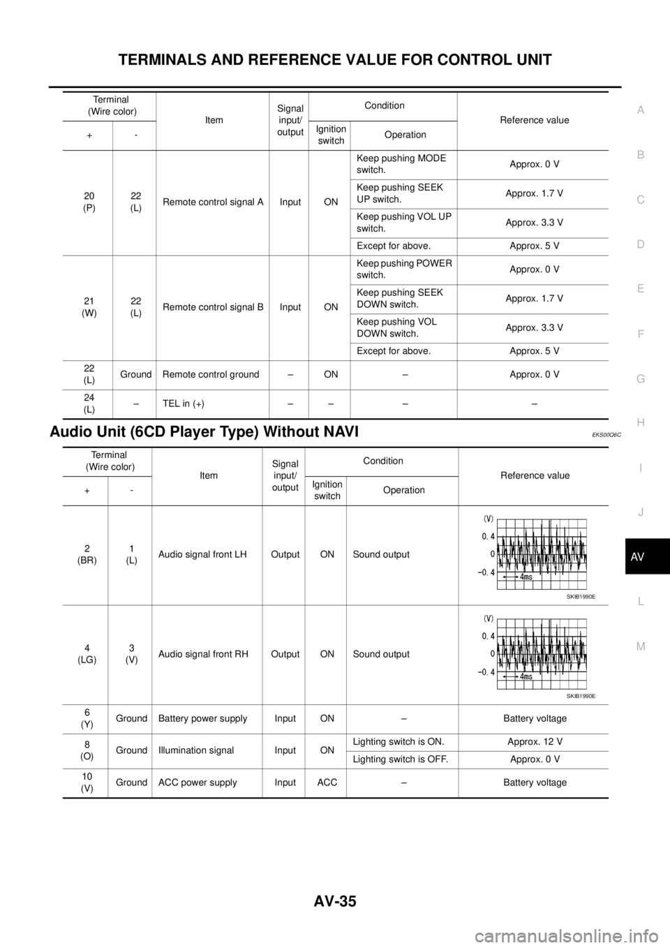
Audio Unit (6CD Player Type) Without NAVIEKS00Q6C
20
(P)22
(L)Remote control signal A Input ONKeep pushing MODE
switch.Approx. 0 V
Keep pushing SEEK
UP switch.Approx. 1.7 V
Keep pushing VOL UP
switch.Approx. 3.3 V
Except for above. Approx. 5 V
21
(W)22
(L)Remote control signal B Input ONKeep pushing POWER
switch.Approx. 0 V
Keep pushing SEEK
DOWN switch.Approx. 1.7 V
Keep pushing VOL
DOWN switch.Approx. 3.3 V
Except for above. Approx. 5 V
22
(L)Ground Remote control ground – ON – Approx. 0 V
24
(L)–TELin(+) – – – – Terminal
(Wire color)
ItemSignal
input/
outputCondition
Reference value
+-Ignition
switchOperation
Terminal
(Wire color)
ItemSignal
input/
outputCondition
Reference value
+-Ignition
switchOperation
2
(BR)1
(L)Audio signal front LH Output ON Sound output
4
(LG)3
(V)Audio signal front RH Output ON Sound output
6
(Y)Ground Battery power supply Input ON – Battery voltage
8
(O)Ground Illumination signal Input ONLighting switch is ON. Approx. 12 V
Lighting switch is OFF. Approx. 0 V
10
(V)Ground ACC power supply Input ACC – Battery voltage
SKIB1990E
SKIB1990E
Page 524 of 3171
AV-36
TERMINALS AND REFERENCE VALUE FOR CONTROL UNIT
14
(L)13
(V)Audio signal rear LH Output ON Sound output
16
(GR)15
(V)Audio signal rear RH Output ON Sound output
18
(W)GroundVehicle speed signal
(2-pulse)Input ONWhen vehicle speed is
approx. 40 km/h (25
MPH).
20
(SB)– Immobilizer – – – –
22
(P)25
(L)Remote control signal A Input ONKeep pushing MODE
switch.Approx. 0 V
Keep pushing SEEK UP
switch.Approx. 1.7 V
Keep pushing VOL UP
switch.Approx. 3.3 V
Except for above. Approx. 5 V
23
(W)25
(L)Remote control signal B Input ONKeep pushing POWER
switch.Approx. 0 V
Keep pushing SEEK
DOWN switch.Approx. 1.7 V
Keep pushing VOL
DOWN switch.Approx. 3.3 V
Except for above. Approx. 5V
25
(L)Ground Remote control ground – ON – Approx. 0 V
26
(W)–TELin(–) – – – –
27
(L)–TELin(+) – – – –
28
(Y)–TELmute – – – – Terminal
(Wire color)
ItemSignal
input/
outputCondition
Reference value
+-Ignition
switchOperation
SKIB1990E
SKIB1990E
ELF1080D