Page 407 of 3171

TROUBLE DIAGNOSIS
ATC-73
C
D
E
F
G
H
I
K
L
MA
B
AT C
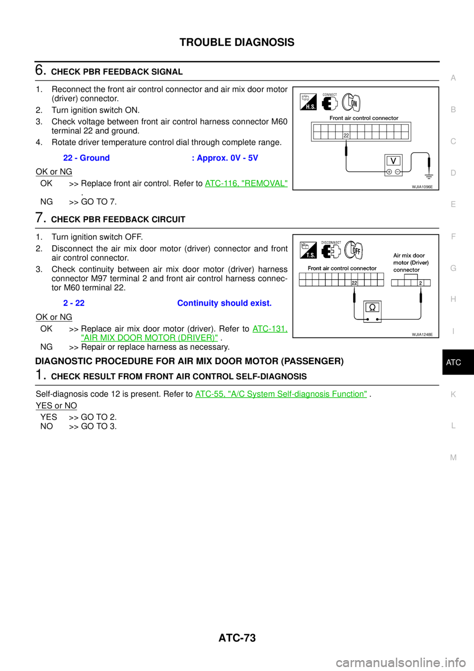
6.CHECK PBR FEEDBACK SIGNAL
1. Reconnect the front air control connector and air mix door motor
(driver) connector.
2. Turn ignition switch ON.
3. Check voltage between front air control harness connector M60
terminal 22 and ground.
4. Rotate driver temperature control dial through complete range.
OK or NG
OK >> Replace front air control. Refer toAT C - 11 6 , "REMOVAL"
.
NG >> GO TO 7.
7.CHECK PBR FEEDBACK CIRCUIT
1. Turn ignition switch OFF.
2. Disconnect the air mix door motor (driver) connector and front
air control connector.
3. Check continuity between air mix door motor (driver) harness
connector M97 terminal 2 and front air control harness connec-
tor M60 terminal 22.
OK or NG
OK >> Replace air mix door motor (driver). Refer toATC-131,
"AIR MIX DOOR MOTOR (DRIVER)".
NG >> Repair or replace harness as necessary.
DIAGNOSTIC PROCEDURE FOR AIR MIX DOOR MOTOR (PASSENGER)
1.CHECK RESULT FROM FRONT AIR CONTROL SELF-DIAGNOSIS
Self-diagnosis code 12 is present. Refer toAT C - 5 5 , "
A/C System Self-diagnosis Function".
YES or NO
YES >> GO TO 2.
NO >> GO TO 3.22 - Ground : Approx. 0V - 5V
WJIA1096E
2 - 22 Continuity should exist.
WJIA1248E
Page 408 of 3171
ATC-74
TROUBLE DIAGNOSIS
2.CHECK POWER SUPPLY CIRCUIT FOR AIR MIX DOOR MOTOR (PASSENGER)
1. Turn ignition switch OFF.
2. Disconnect front air control connector and air mix door motor
(passenger) connector.
3. Check continuity between front air control harness connector
M60 terminal 15 and 16 and air mix door motor (passenger) har-
ness connector M100 terminal 6 and 5.
OK or NG
OK >> Replace air mix door motor (passenger). Refer toAT C -
131, "AIR MIX DOOR MOTOR (PASSENGER)".
NG >> Repair or replace harness as necessary.
3.CHECK PBR REFERENCE SIGNAL VOLTAGE
1. Turn ignition switch OFF.
2. Disconnect the air mix door motor (passenger) connector.
3. Turn ignition switch ON.
4. Check voltage between air mix door motor (passenger) harness
connector M100 terminal 1 and ground.
OK or NG
OK >> GO TO 5.
NG >> GO TO 4.15 - 6 Continuity should exist.
16 - 5 Continuity should exist.
MJIB0059E
1 - Ground : Approx. 5V
MJIB0060E
Page 409 of 3171
TROUBLE DIAGNOSIS
ATC-75
C
D
E
F
G
H
I
K
L
MA
B
AT C
4.CHECK PBR REFERENCE VOLTAGE CIRCUIT BETWEEN AIR MIX DOOR (PASSENGER) AND
FRONT AIR CONTROL
1. Turn ignition switch OFF.
2. Disconnect the front air control connector.
3. Check continuity between air mix door motor (passenger) har-
ness connector M100 terminal 1 and front air control harness
connector M60 terminal 23.
OK or NG
OK >> Replace front air control. Refer toAT C - 11 6 , "REMOVAL"
.
NG >> Repair or replace harness as necessary.
5.CHECK PBR GROUND REFERENCE CIRCUIT
1. Turn ignition switch OFF.
2. Disconnect the front air control connector.
3. Check continuity between air mix door motor (passenger) har-
ness connector M100 terminal 3 and front air control harness
connector M60 terminal 26.
OK or NG
OK >> GO TO 6.
NG >> Repair or replace harness as necessary.1 - 23 Continuity should exist.
MJIB0061E
3 - 26 Continuity should exist.
MJIB0062E
Page 410 of 3171
ATC-76
TROUBLE DIAGNOSIS
6.CHECK PBR FEEDBACK SIGNAL
1. Reconnect the front air control connector and air mix door motor
(passenger) connector.
2. Turn ignition switch ON.
3. Check voltage between front air control harness connector M61
terminal 36 and ground.
4. Rotate passenger temperature control dial through complete
range.
OK or NG
OK >> Replace front air control. Refer toAT C - 11 6 , "REMOVAL"
.
NG >> GO TO 7.
7.CHECK PBR FEEDBACK CIRCUIT
1. Turn ignition switch OFF.
2. Disconnect the air mix door motor (passenger) connector and
front air control connector.
3. Check continuity between air mix door motor (passenger) har-
ness connector M100 terminal 2 and front air control harness
connector M61 terminal 36.
OK or NG
OK >> Replace air mix door motor (passenger). Refer toAT C -
131, "AIR MIX DOOR MOTOR (PASSENGER)".
NG >> Repair or replace harness as necessary.36 - Ground : Approx. 0 - 5V
WJIA1249E
2 - 36 : Continuity should exist.
MJIB0063E
Page 413 of 3171

TROUBLE DIAGNOSIS
ATC-79
C
D
E
F
G
H
I
K
L
MA
B
AT C
COMPONENT DESCRIPTION
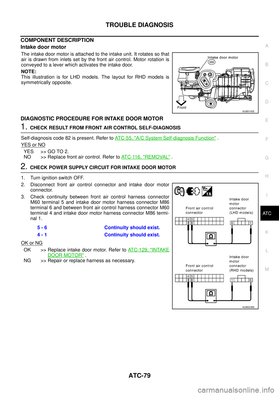
Intake door motor
The intake door motor is attached to the intake unit. It rotates so that
air is drawn from inlets set by the front air control. Motor rotation is
conveyed to a lever which activates the intake door.
NOTE:
This illustration is for LHD models. The layout for RHD models is
symmetrically opposite.
DIAGNOSTIC PROCEDURE FOR INTAKE DOOR MOTOR
1.CHECK RESULT FROM FRONT AIR CONTROL SELF-DIAGNOSIS
Self-diagnosis code 82 is present. Refer toAT C - 5 5 , "
A/C System Self-diagnosis Function".
YES or NO
YES >> GO TO 2.
NO >> Replace front air control. Refer toAT C - 11 6 , "
REMOVAL".
2.CHECK POWER SUPPLY CIRCUIT FOR INTAKE DOOR MOTOR
1. Turn ignition switch OFF.
2. Disconnect front air control connector and intake door motor
connector.
3. Check continuity between front air control harness connector
M60 terminal 5 and intake door motor harness connector M86
terminal 6 and between front air control harness connector M60
terminal 4 and intake door motor harness connector M86 termi-
nal 1.
OK or NG
OK >> Replace intake door motor. Refer toATC-129, "INTAKE
DOOR MOTOR".
NG >> Repair or replace harness as necessary.
MJIB0165E
5 - 6 Continuity should exist.
4 - 1 Continuity should exist.
MJIB0208E
Page 417 of 3171
![NISSAN NAVARA 2005 Repair Workshop Manual TROUBLE DIAGNOSIS
ATC-83
C
D
E
F
G
H
I
K
L
MA
B
AT C
1.CHECK FUSES
Check 15A fuses [No. 24 and 27, (located in the fuse and fusible link box)]. For fuse layout, refer toPG-84,
"FUSE AND FUSIBLE LINK B NISSAN NAVARA 2005 Repair Workshop Manual TROUBLE DIAGNOSIS
ATC-83
C
D
E
F
G
H
I
K
L
MA
B
AT C
1.CHECK FUSES
Check 15A fuses [No. 24 and 27, (located in the fuse and fusible link box)]. For fuse layout, refer toPG-84,
"FUSE AND FUSIBLE LINK B](/manual-img/5/57362/w960_57362-416.png)
TROUBLE DIAGNOSIS
ATC-83
C
D
E
F
G
H
I
K
L
MA
B
AT C
1.CHECK FUSES
Check 15A fuses [No. 24 and 27, (located in the fuse and fusible link box)]. For fuse layout, refer toPG-84,
"FUSE AND FUSIBLE LINK BOX".
OK or NG
OK >> GO TO 2.
NG >> GO TO 10.
2.CHECK BLOWER MOTOR POWER SUPPLY CIRCUIT
1. Turn ignition switch OFF.
2. Disconnect blower motor connector.
3. Turn ignition switch ON.
4. Turn the blower control dial to select any mode except off.
5. Check voltage between blower motor harness connector M94
terminal 2 and ground.
OK or NG
OK >> GO TO 12.
NG >> GO TO 3.
3.CHECK BLOWER MOTOR RELAY (SWITCH SIDE) POWER SUPPLY CIRCUIT
1. Turn ignition switch OFF.
2. Disconnect blower motor relay.
3. Check voltage between blower motor relay harness connector
E28 terminals 3 and 6 and ground.
OK or NG
OK >> GO TO 4.
NG >> Repair harness or connector.
4.CHECK BLOWER MOTOR RELAY
Refer toAT C - 8 6 , "
Blower Motor Relay".
OK or NG
OK >> GO TO 5.
NG >> Replace blower motor relay.
5.CHECK BLOWER MOTOR RELAY (SWITCH SIDE) CIRCUIT FOR OPEN
1. Turn ignition switch OFF.
2. Disconnect blower motor relay connector and blower motor con-
nector.
3. Check continuity between blower motor relay harness connector
E28 terminals 5 and 7 and blower motor harness connector M94
terminal 2.
OK or NG
OK >> GO TO 6.
NG >> Repair harness or connector.Fuses are good.
2 - Ground : Battery voltage.
MJIB0065E
3, 6 - Ground : Battery voltage.
MJIB0066E
5, 7 - 2 : Continuity should exist.
MJIB0067E
Page 418 of 3171

ATC-84
TROUBLE DIAGNOSIS
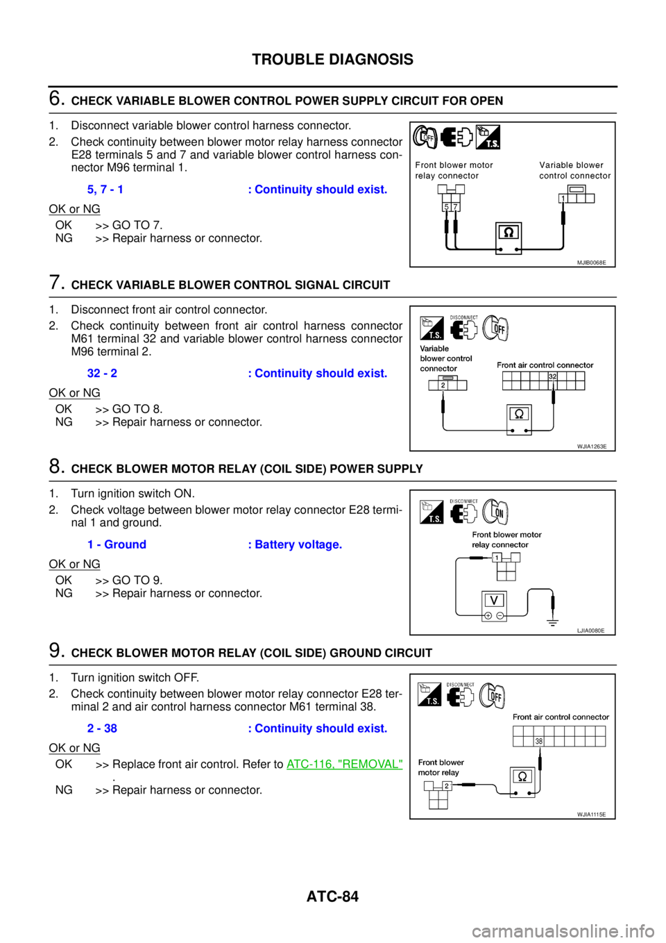
6.CHECK VARIABLE BLOWER CONTROL POWER SUPPLY CIRCUIT FOR OPEN
1. Disconnect variable blower control harness connector.
2. Check continuity between blower motor relay harness connector
E28 terminals 5 and 7 and variable blower control harness con-
nector M96 terminal 1.
OK or NG
OK >> GO TO 7.
NG >> Repair harness or connector.
7.CHECK VARIABLE BLOWER CONTROL SIGNAL CIRCUIT
1. Disconnect front air control connector.
2. Check continuity between front air control harness connector
M61 terminal 32 and variable blower control harness connector
M96 terminal 2.
OK or NG
OK >> GO TO 8.
NG >> Repair harness or connector.
8.CHECK BLOWER MOTOR RELAY (COIL SIDE) POWER SUPPLY
1. Turn ignition switch ON.
2. Check voltage between blower motor relay connector E28 termi-
nal 1 and ground.
OK or NG
OK >> GO TO 9.
NG >> Repair harness or connector.
9.CHECK BLOWER MOTOR RELAY (COIL SIDE) GROUND CIRCUIT
1. Turn ignition switch OFF.
2. Check continuity between blower motor relay connector E28 ter-
minal 2 and air control harness connector M61 terminal 38.
OK or NG
OK >> Replace front air control. Refer toAT C - 11 6 , "REMOVAL"
.
NG >> Repair harness or connector.5, 7 - 1 : Continuity should exist.
MJIB0068E
32 - 2 : Continuity should exist.
WJIA1263E
1 - Ground : Battery voltage.
LJIA0080E
2 - 38 : Continuity should exist.
WJIA1115E
Page 419 of 3171
TROUBLE DIAGNOSIS
ATC-85
C
D
E
F
G
H
I
K
L
MA
B
AT C
10.REPLACE FUSES
1. Replace fuses.
2. Activate the blower motor.
3. Do fuses blow?
YES or NO
YES >> GO TO 11.
NO >> Inspection End.
11 .CHECK BLOWER MOTOR POWER SUPPLY CIRCUIT FOR SHORT
1. Turn ignition switch OFF.
2. Disconnect blower motor connector and variable blower control
connector.
3. Check continuity between variable blower control harness con-
nector M96 terminal 1 and ground.
OK or NG
OK >> GO TO 12.
NG >> Repair harness or connector.
12.CHECK VARIABLE BLOWER CONTROL SIGNAL CIRCUIT
1. Disconnect front air control connector.
2. Check continuity between front air control harness connector
M61 terminal 32 and variable blower control harness connector
M96 terminal 2.
OK or NG
OK >> Check blower motor. If OK, replace variable blower con-
trol. Refer toATC-121, "
REMOVAL".
NG >> Repair harness or connector.1 - Ground : Continuity should not exist.
WJIA1264E
32 - 2 : Continuity should exist.
WJIA1263E