Page 525 of 3171

TERMINALS AND REFERENCE VALUE FOR CONTROL UNIT
AV-37
C
D
E
F
G
H
I
J
L
MA
B
AV
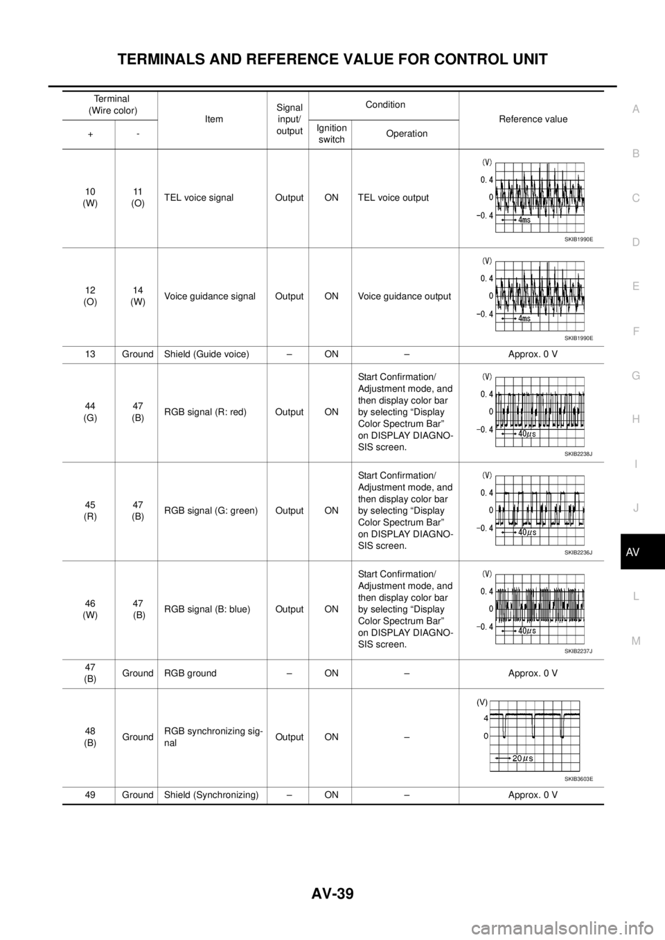
Audio Unit (With NAVI)EKS00Q6D
Terminal
(Wire color)
ItemSignal
input/
outputCondition
Reference value
+-Ignition
switchOperation
3
(Y)–Communication
signal (H)Input/
output–– –
4
(R)–Communication
signal (L)Input/
output–– –
10
(W)11
(O)TEL voice signal Input ON TEL voice output
12
(O)13
(W)Voice guidance signal Input ON Voice guidance output
17 Ground Shield (TEL voice) – ON – Approx. 0 V
18 Ground Shield (Guide voice) – ON – Approx. 0 V
22
(BR)23
(L)Audio signal front LH Output ON Sound output
24
(L)25
(V)Audio signal rear LH Output ON Sound output
26
(P)35
(L)Remote control signal A Input ONKeep pushing SOURCE
switch.approx. 0 V
Keep pushing MENU
UP switch.Approx. 1.2 V
Keep pushing MENU
DOWN switch.Approx. 2.5 V
Keep pushing ENTER
switch.Approx. 3.7 V
Except for above. Approx. 5 V
27
(V)Ground ACC power supply Input ACC – Battery voltage
28
(B)GroundIllumination control sig-
nalInput ONIllumination control
switch is operated by
lighting switch in ON
positionChanges between approx. 0 V
and approx. 12 V
SKIB1990E
SKIB1990E
SKIB1990E
SKIB1990E
Page 526 of 3171

AV-38
TERMINALS AND REFERENCE VALUE FOR CONTROL UNIT
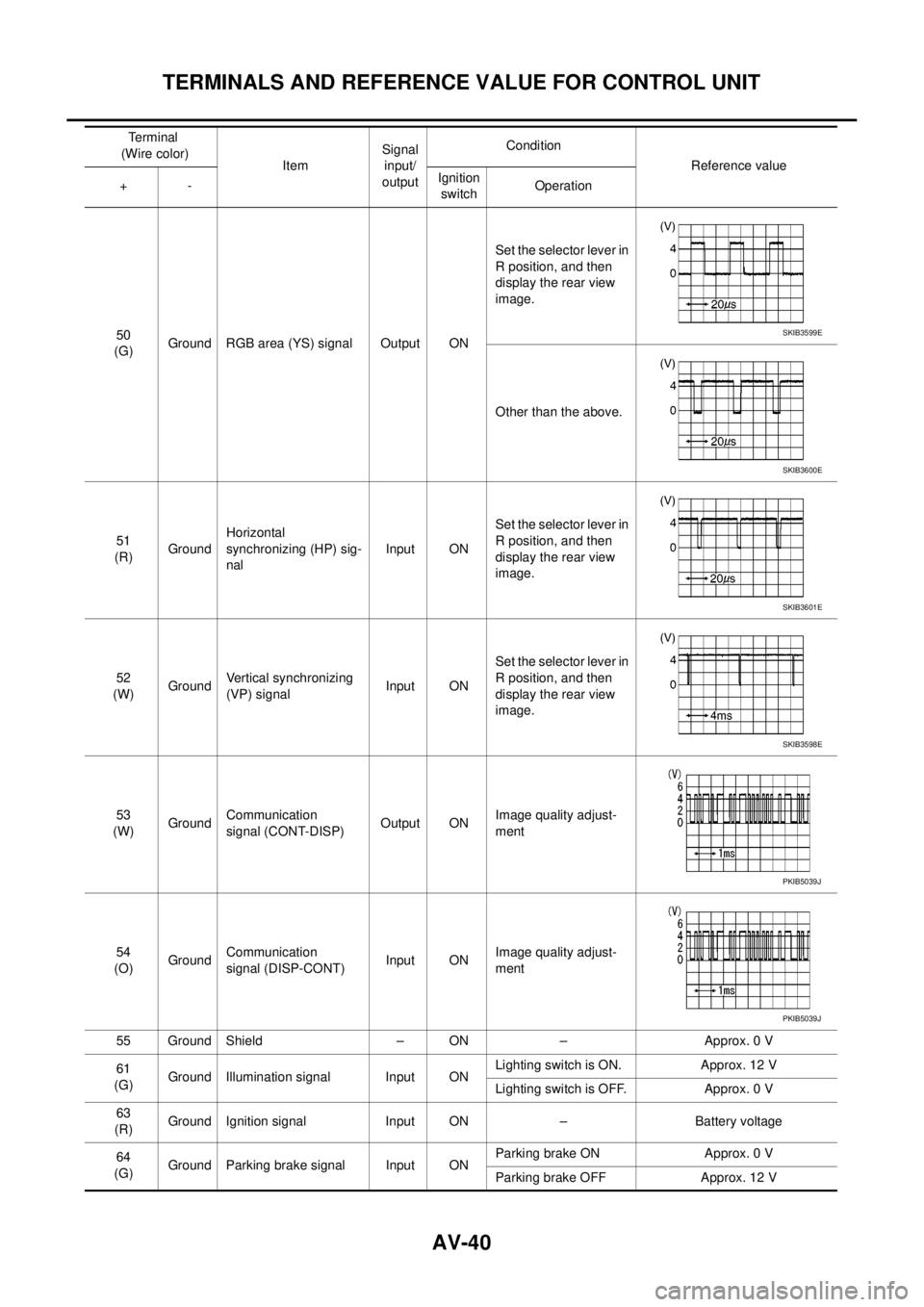
NAVI Control Unit
EKS00Q6E
29
(O)Ground Illumination signal Input ONLighting switch is ON. Approx. 12 V
Lighting switch is OFF. Approx. 0 V
31
(LG)32
(V)Audio signal front RH Output ON Sound output
33
(GR)34
(V)Audio signal rear RH Output ON Sound output
36
(W)35
(L)Remote control signal B Input ONKeep pushing VOL
DOWN switch.Approx. 0 V
Keep pushing VOL UP
switch.Approx. 1.2 V
Keep pushing TEL, PTT
switch.Approx. 2.5 V
Keep pushing BACK
switch.Approx. 3.7 V
Except for above. Approx. 5 V
39
(Y)Ground Battery power supply Input ON – Battery voltage Terminal
(Wire color)
ItemSignal
input/
outputCondition
Reference value
+-Ignition
switchOperation
SKIB1990E
SKIB1990E
Terminal
(Wire color)
ItemSignal
input/
outputCondition
Reference value
+-Ignition
switchOperation
1
(B)Ground Ground – ON – Approx. 0 V
2
(Y)Ground Battery power supply Input ON – Battery voltage
5
(V)Ground ACC power supply Input ACC – Battery voltage
6
(B)Ground MIC. power supply Output ON – Approx. 5 V
7 Ground Shield (MIC.) – ON – Approx. 0 V
8
(W)Ground MIC. signal Input ON Sounds
9 Ground Shield (TEL voice) – ON – Approx. 0 V
PKIB5037J
Page 527 of 3171

TERMINALS AND REFERENCE VALUE FOR CONTROL UNIT
AV-39
C
D
E
F
G
H
I
J
L
MA
B
AV
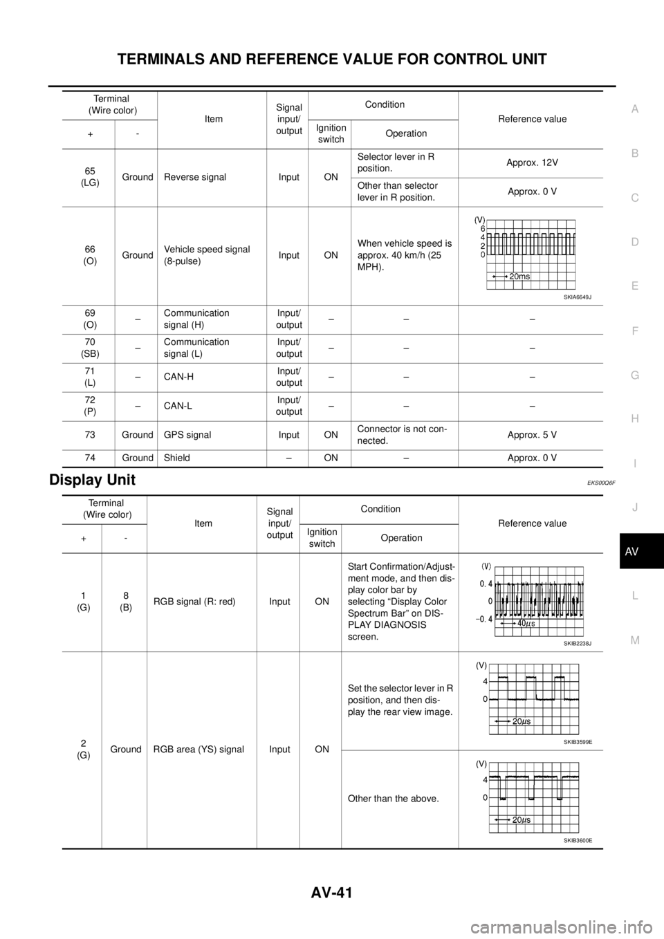
10
(W)11
(O)TEL voice signal Output ON TEL voice output
12
(O)14
(W)Voice guidance signal Output ON Voice guidance output
13 Ground Shield (Guide voice) – ON – Approx. 0 V
44
(G)47
(B)RGB signal (R: red) Output ONStart Confirmation/
Adjustment mode, and
then display color bar
by selecting “Display
Color Spectrum Bar”
on DISPLAY DIAGNO-
SIS screen.
45
(R)47
(B)RGB signal (G: green) Output ONStart Confirmation/
Adjustment mode, and
then display color bar
by selecting “Display
Color Spectrum Bar”
on DISPLAY DIAGNO-
SIS screen.
46
(W)47
(B)RGB signal (B: blue) Output ONStart Confirmation/
Adjustment mode, and
then display color bar
by selecting “Display
Color Spectrum Bar”
on DISPLAY DIAGNO-
SIS screen.
47
(B)Ground RGB ground – ON – Approx. 0 V
48
(B)GroundRGB synchronizing sig-
nalOutput ON –
49 Ground Shield (Synchronizing) – ON – Approx. 0 VTerminal
(Wire color)
ItemSignal
input/
outputCondition
Reference value
+-Ignition
switchOperation
SKIB1990E
SKIB1990E
SKIB2238J
SKIB2236J
SKIB2237J
SKIB3603E
Page 528 of 3171

AV-40
TERMINALS AND REFERENCE VALUE FOR CONTROL UNIT
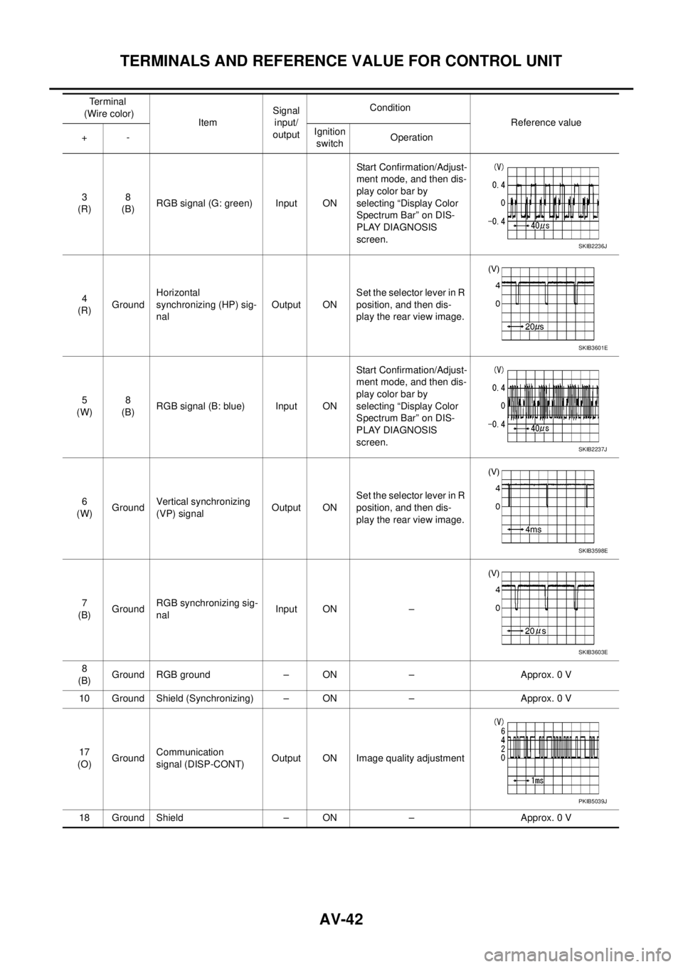
50
(G)Ground RGB area (YS) signal Output ONSet the selector lever in
R position, and then
display the rear view
image.
Other than the above.
51
(R)GroundHorizontal
synchronizing (HP) sig-
nalInput ONSet the selector lever in
R position, and then
display the rear view
image.
52
(W)GroundVertical synchronizing
(VP) signalInput ONSet the selector lever in
R position, and then
display the rear view
image.
53
(W)GroundCommunication
signal (CONT-DISP)Output ONImage quality adjust-
ment
54
(O)GroundCommunication
signal (DISP-CONT)Input ONImage quality adjust-
ment
55 Ground Shield – ON – Approx. 0 V
61
(G)Ground Illumination signal Input ONLighting switch is ON. Approx. 12 V
Lighting switch is OFF. Approx. 0 V
63
(R)Ground Ignition signal Input ON – Battery voltage
64
(G)Ground Parking brake signal Input ONParking brake ON Approx. 0 V
Parking brake OFF Approx. 12 V Terminal
(Wire color)
ItemSignal
input/
outputCondition
Reference value
+-Ignition
switchOperationSKIB3599E
SKIB3600E
SKIB3601E
SKIB3598E
PKIB5039J
PKIB5039J
Page 529 of 3171

TERMINALS AND REFERENCE VALUE FOR CONTROL UNIT
AV-41
C
D
E
F
G
H
I
J
L
MA
B
AV
Display UnitEKS00Q6F
65
(LG)Ground Reverse signal Input ONSelector lever in R
position.Approx. 12V
Other than selector
lever in R position.Approx. 0 V
66
(O)GroundVehicle speed signal
(8-pulse)Input ONWhen vehicle speed is
approx. 40 km/h (25
MPH).
69
(O)–Communication
signal (H)Input/
output–– –
70
(SB)–Communication
signal (L)Input/
output–– –
71
(L)–CAN-HInput/
output–– –
72
(P)–CAN-LInput/
output–– –
73 Ground GPS signal Input ONConnector is not con-
nected.Approx. 5 V
74 Ground Shield – ON – Approx. 0 VTerminal
(Wire color)
ItemSignal
input/
outputCondition
Reference value
+-Ignition
switchOperation
SKIA6649J
Terminal
(Wire color)
ItemSignal
input/
outputCondition
Reference value
+-Ignition
switchOperation
1
(G)8
(B)RGB signal (R: red) Input ONStart Confirmation/Adjust-
ment mode, and then dis-
play color bar by
selecting “Display Color
Spectrum Bar” on DIS-
PLAY DIAGNOSIS
screen.
2
(G)Ground RGB area (YS) signal Input ONSet the selector lever in R
position, and then dis-
play the rear view image.
Other than the above.
SKIB2238J
SKIB3599E
SKIB3600E
Page 530 of 3171

AV-42
TERMINALS AND REFERENCE VALUE FOR CONTROL UNIT
3
(R)8
(B)RGB signal (G: green) Input ONStart Confirmation/Adjust-
ment mode, and then dis-
play color bar by
selecting “Display Color
Spectrum Bar” on DIS-
PLAY DIAGNOSIS
screen.
4
(R)GroundHorizontal
synchronizing (HP) sig-
nalOutput ONSet the selector lever in R
position, and then dis-
play the rear view image.
5
(W)8
(B)RGB signal (B: blue) Input ONStart Confirmation/Adjust-
ment mode, and then dis-
play color bar by
selecting “Display Color
Spectrum Bar” on DIS-
PLAY DIAGNOSIS
screen.
6
(W)GroundVertical synchronizing
(VP) signalOutput ONSet the selector lever in R
position, and then dis-
play the rear view image.
7
(B)GroundRGB synchronizing sig-
nalInput ON –
8
(B)Ground RGB ground – ON – Approx. 0 V
10 Ground Shield (Synchronizing) – ON – Approx. 0 V
17
(O)GroundCommunication
signal (DISP-CONT)Output ON Image quality adjustment
18 Ground Shield – ON – Approx. 0 VTerminal
(Wire color)
ItemSignal
input/
outputCondition
Reference value
+-Ignition
switchOperation
SKIB2236J
SKIB3601E
SKIB2237J
SKIB3598E
SKIB3603E
PKIB5039J
Page 531 of 3171
TERMINALS AND REFERENCE VALUE FOR CONTROL UNIT
AV-43
C
D
E
F
G
H
I
J
L
MA
B
AV
19
(W)GroundCommunication
signal (CONT-DISP)Input ON Image quality adjustment
20
(V)Ground ACC power supply Input ACC – Battery voltage
21
(Y)Ground Battery power supply Input ON – Battery voltage
23
(B)Ground Ground – ON – Approx. 0 V Terminal
(Wire color)
ItemSignal
input/
outputCondition
Reference value
+-Ignition
switchOperation
PKIB5039J
Page 532 of 3171

AV-44
DIAGNOSIS SYSTEM
DIAGNOSIS SYSTEM
PFP:00000
Navigation System Diagnosis FunctionEKS00Q6H
lThere are 2 diagnosis functions (on board diagnosis and diagnosis using CONSULT-II), and it is neces-
sary to use them properly according to the condition. If the on board diagnosis starts, perform diagnosis
with on board diagnosis. If the on board diagnosis does not start (the cause being that the system is not
started, the switch operation is not activated, etc.), perform diagnosis using CONSULT-II.
lAt on board diagnosis, the NAVI control unit diagnosis function starts by switch operation and the NAVI
control unit performs the diagnosis for each unit of system.
lAt diagnosis using CONSULT-II, the NAVI control unit diagnosis function starts by the communication
between CONSULT-II and NAVI control unit, and the NAVI control unit performs the diagnosis for each
unit of system.
On Bord Self-Diagnosis FunctionEKS00Q6I
DESCRIPTION
lThe on board diagnosis function has a self-diagnosis mode for performing trouble diagnosis automatically
and a Confirmation/Adjustment mode for operating manually.
lSelf-diagnosis mode performs the diagnosis at NAVI control unit, connections between each unit that
composes the system, and connections between NAVI control unit and GPS antenna. It displays the
results on the display.
lConfirmation/Adjustment mode is used to monitor the vehicle signals requiring operation and judgement
by a technician (malfunctions that cannot be automatically judged by the system), the confirmation/adjust-
ment of setting value, the error history of system, and the communication condition of system.
DIAGNOSIS ITEM
Mode Description
Self Diagnosis
lNAVI control unit diagnosis (DVD-ROM drive will not be diagnosed when
no map DVD-ROM is in it.)
lThe connection diagnosis between NAVI control unit and GPS antenna
and the connection diagnosis between NAVI control unit and each unit
can be performed.
Confirma-
tion/Adjust-
mentDisplay DiagnosisThe tint can be confirmed by the color spectrum bar display. The shading
of color can be confirmed by the gradation bar display.
Vehicle SignalsDiagnosis of signals can be performed for vehicle speed, parking brake,
lights, ignition (ignition switch), and reverse.
Speaker Test The connection of a speaker can be confirmed by test tone.
NavigationSteering Angle
AdjustmentWhen there is a difference between the actual turning angle and the vehi-
cle mark turning angle, it can be adjusted.
Speed CalibrationWhen there is a difference between the current location mark and the
actual location, it can be adjusted.
Error HistoryThe system malfunction and its frequency that occurred in the past are dis-
played. When the malfunctioning item is selected, the time and place that
the selected malfunction last occurred are displayed.
Vehicle CAN Diagnosis The transmitting/receiving of CAN communication can be monitored.
AV COMM DiagnosisThe communication condition of each unit that composes the system can
be monitored.
Handsfree PhoneEach setting of hands-free volume adjustment, voice microphone test,
delete hands-free memory can be performed.
Bluetooth Passkey and device name can be confirmed/changed.
Delete Unit Commection Log The connection history and error history of unit can be deleted.