2005 NISSAN NAVARA ignition
[x] Cancel search: ignitionPage 558 of 3171
AV-70
TROUBLE DIAGNOSIS
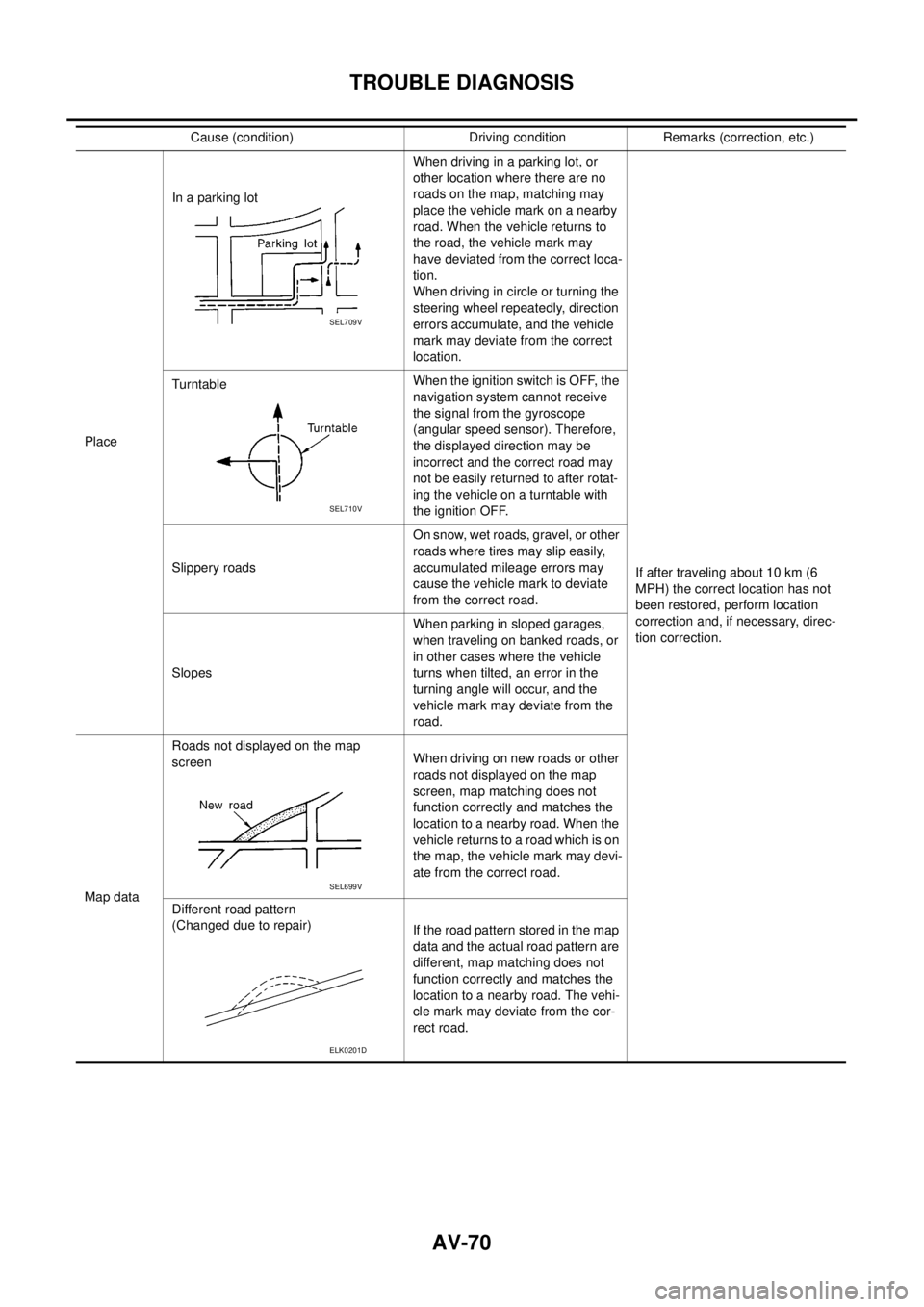
PlaceIn a parking lotWhen driving in a parking lot, or
other location where there are no
roads on the map, matching may
place the vehicle mark on a nearby
road. When the vehicle returns to
the road, the vehicle mark may
have deviated from the correct loca-
tion.
When driving in circle or turning the
steering wheel repeatedly, direction
errors accumulate, and the vehicle
mark may deviate from the correct
location.
If after traveling about 10 km (6
MPH) the correct location has not
been restored, perform location
correction and, if necessary, direc-
tion correction. TurntableWhentheignitionswitchisOFF,the
navigation system cannot receive
the signal from the gyroscope
(angular speed sensor). Therefore,
the displayed direction may be
incorrect and the correct road may
not be easily returned to after rotat-
ing the vehicle on a turntable with
the ignition OFF.
Slippery roadsOn snow, wet roads, gravel, or other
roads where tires may slip easily,
accumulated mileage errors may
cause the vehicle mark to deviate
from the correct road.
SlopesWhen parking in sloped garages,
when traveling on banked roads, or
in other cases where the vehicle
turns when tilted, an error in the
turning angle will occur, and the
vehicle mark may deviate from the
road.
Map dataRoads not displayed on the map
screenWhen driving on new roads or other
roads not displayed on the map
screen, map matching does not
function correctly and matches the
location to a nearby road. When the
vehicle returns to a road which is on
the map, the vehicle mark may devi-
ate from the correct road.
Different road pattern
(Changed due to repair)
If the road pattern stored in the map
data and the actual road pattern are
different, map matching does not
function correctly and matches the
location to a nearby road. The vehi-
cle mark may deviate from the cor-
rect road. Cause (condition) Driving condition Remarks (correction, etc.)
SEL709V
SEL710V
SEL699V
ELK0201D
Page 560 of 3171

AV-72
TROUBLE DIAGNOSIS
–Because calculation of the current location cannot be done when traveling with the ignition OFF, for exam-
ple when traveling by ferry or when being towed, the location before travel is displayed. If the precise loca-
tioncanbedetectedwithGPS,thelocationwillbecorrected.
THE CURRENT POSITION MARK JUMPS.
In the following cases, the current location mark may appear to jump as a result of automatic correction of the
current location.
lWhen map matching has been done
–If current location and the current location mark are different when map matching is done, the current
location mark may seem to jump. At this time, the location may be “corrected” to the incorrect road or to a
location which is not on a road.
lWhen GPS location correction has been done
–If current location and the current location mark are different when location is corrected using GPS mea-
surements, the current location mark may seem to jump. At this time, the location may be “corrected” to a
location which is not on a road.
THE CURRENT LOCATION MARK IS IN A RIVER OR THE SEA.
The navigation system moves the current location mark with no distinction between land and rivers or sea. If
the location mark is somehow out of place, it may appear that the vehicle is driving in a river or the sea.
CURRENT LOCATION MARK ROTATES WITHOUT OPERATION
If the ignition switch is turned ON with the turntable rotating, the rotating condition is recorded as the stop con-
dition. Therefore, the current location mark might rotate when actually stopping.
WHEN DRIVING ON THE SAME ROAD, SOMETIMES THE CURRENT LOCATION MARK IS IN
THE CORRECT PLACE AND SOMETIMES IT IS IN THE INCORRECT PLACE.
The conditions of the GPS antenna (GPS data) and gyroscope (angular speed sensor) change gradually.
Depending on the road traveled and operation of the steering wheel, the location detection results will be dif-
ferent. Therefore, even on a road on which the location has never been incorrect, conditions may cause the
vehicle mark to deviate.
LOCATION CORRECTION BY MAP MATCHING IS SLOW.
lThe map matching function needs to refer to the data of the surrounding area. It is necessary to drive
some distance for the function to work.
lBecause of the way map matching operates, when there are many roads running in similar directions in
the surrounding area a matching determination may be impossible. The location will remain uncorrected
until some special feature is found.
ALTHOUGH THE GPS RECEIVING DISPLAY IS GREEN, THE VEHICLE MARK DOES NOT
RETURN TO THE CORRECT LOCATION.
lGPS accuracy has a malfunction range of about 10 m. In some cases the current location mark may not
be on the correct street, even when GPS location correction is done.
lThe navigation system compares the results of GPS location detection with the results from map-match-
ing location detection. The one that is determined to have higher accuracy is used.
lPosition correction by GPS is not available while the vehicle is stopped.
THE NAME OF THE CURRENT PLACE IS NOT DISPLAYED.
The current place name might not be displayed when there is no name of place information in the map screen.
THE DISPLAY IS DIFFERENT BETWEEN BIRDVIEW®AND (FLAT) MAP DISPLAY.
The following is different at birdview®.
lThe current place name displays names that are primarily in the direction of vehicle travel.
lThe amount of time before the vehicle travel or turn angle is updated on the screen is longer than for the
(flat) map display.
lThe conditions for display of place names, roads, and other data are different for nearby areas and for
more distant areas.
lSome trimming of the character data is done to prevent the display from becoming too complex. In some
cases and in some locations, the display contents may differ.
lThe same place name, street name, etc. may be displayed multiple times.
Page 573 of 3171
BCM (BODY CONTROL MODULE)
BCS-7
C
D
E
F
G
H
I
J
L
MA
B
BCS
BCM STATUS CONTROL
BCM changes its status depending on the operation status in order to save power consumption.
1. CAN communication status
lWith ignition switch ON, CAN communicates with other control units normally.
lControl by BCM is being operated properly.
lWhen ignition switch is OFF, switching to sleep mode is possible.
lEven when ignition switch is OFF, if CAN communication with IPDM E/R and combination meter is
active, CAN communication status is active.
2. Sleep transient status
lThis status shuts down CAN communication when ignition switch is turned OFF.
lIt transmits sleep request signal to IPDM E/R and combination meter.
lTwo seconds after CAN communication of all control units stops, CAN communication switches to inac-
tive status.
3. CAN communication inactive status
lWith ignition switch OFF, CAN communication is not active.
lWith ignition switch OFF, control performed only by BCM is active.
lThree seconds after CAN communication of all control units stops, CAN communication switches to
inactive status.
4. Sleep status
lBCM is activated with low current consumption mode.
lCAN communication is not active.
lWhen CAN communication operation is detected, it switches to CAN communication status.
lWhen a state of the following switches changes, it switches to CAN communication state:
–Key switch
–Hazard switch
–Door lock/unlock switch
–Front door switch (driver side, passenger side)
–Rear door switch (LH, RH) (double cab)
–Rear door switch (driver side, passenger side) No.1 (king cab)
–Rear door switch (driver side, passenger side) No.2 (king cab)
–Combination switch (passing, lighting switch 1st position, front fog lamp)
–Keyfob (lock/unlock signal)
–Door lock assembly LH (key cylinder switch)
lWhen control performed only by BCM is required by switch, it shifts to CAN communication inactive
mode.
lStatus of combination switch reading function is changed.
Page 575 of 3171

BCM (BODY CONTROL MODULE)
BCS-9
C
D
E
F
G
H
I
J
L
MA
B
BCS
MAJOR COMPONENTS AND CONTROL SYSTEM
CAN Communication System DescriptionEKS00PA2
Refer toLAN-23, "CAN COMMUNICATION".
System Input Output
Remote keyless entry system Keyfob
lAll-door locking actuator
lTurn signal lamp (LH, RH)
lCombination meter (Turn signal
lamp)
Power door lock system Door lock/unlock switch All-door locking actuator
Power supply (IGN) to power win-
dow and sunroofIgnition power supply Power window and sunroof system
Power supply (BAT) to power
window and sunroofBattery power supply Power window and sunroof system
Headlamp Combination switch IPDM E/R
Tail lamp Combination switch IPDM E/R
Front fog lamp Combination switch IPDM E/R
Rear fog lamp Combination switch
lRear fog lamp
lCombination meter
Turn signal lamp Combination switch
lTurn signal lamp
lCombination meter
Hazard lamp Hazard switch
lTurn signal lamp
lCombination meter
Room lamp timer
lKey switch
lKeyfob
lDoor lock/unlock switch
lFront door switch driver side
lAll-door switchInterior room lamp
Light warning chime
lCombination switch
lKey switch
lFront door switch driver sideCombination meter (warning buzzer)
Rain-sensing intermittent wiper
lCombination switch
lLight and rain sensorIPDM E/R
Vehicle-speed-sensing intermit-
tent wiper
lCombination switch
lCombination meterIPDM E/R
Headlamp washer Combination switch IPDM E/R
Rear window defogger
lRear window defogger switch
lIgnition switch (ACC, ON)IPDM E/R
A/C switch signal Front air control ECM
Blower fan switch signal Front air control ECM
Page 580 of 3171
BCS-14
BCM (BODY CONTROL MODULE)
CONSULT-II Function (BCM)
EKS00PA4
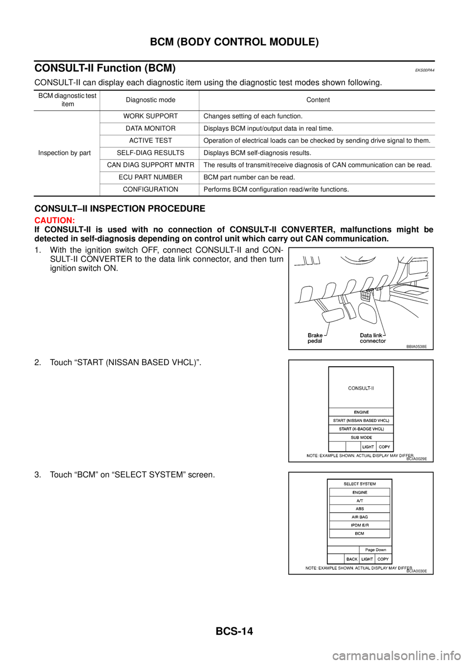
CONSULT-II can display each diagnostic item using the diagnostic test modes shown following.
CONSULT–II INSPECTION PROCEDURE
CAUTION:
If CONSULT-II is used with no connection of CONSULT-II CONVERTER, malfunctions might be
detected in self-diagnosis depending on control unit which carry out CAN communication.
1. With the ignition switch OFF, connect CONSULT-II and CON-
SULT-II CONVERTER to the data link connector, and then turn
ignition switch ON.
2. Touch “START (NISSAN BASED VHCL)”.
3. Touch “BCM” on “SELECT SYSTEM” screen.
BCM diagnostic test
itemDiagnostic mode Content
Inspection by partWORK SUPPORT Changes setting of each function.
DATA MONITOR Displays BCM input/output data in real time.
ACTIVE TEST Operation of electrical loads can be checked by sending drive signal to them.
SELF-DIAG RESULTS Displays BCM self-diagnosis results.
CAN DIAG SUPPORT MNTR The results of transmit/receive diagnosis of CAN communication can be read.
ECU PART NUMBER BCM part number can be read.
CONFIGURATION Performs BCM configuration read/write functions.
BBIA0538E
BCIA0029E
BCIA0030E
Page 583 of 3171
BCM (BODY CONTROL MODULE)
BCS-17
C
D
E
F
G
H
I
J
L
MA
B
BCS
ConfigurationEKS00PA6
Refer toGI-37, "Configuration (BCM)".
Removal and Installation of BCMEKS00PA7
REMOVAL
CAUTION:
If possible, before removing BCM, retrieve current BCM configuration to use for reference when con-
figuring brand-new BCM after installation. Refer toGI-37, "
Configuration (BCM)".
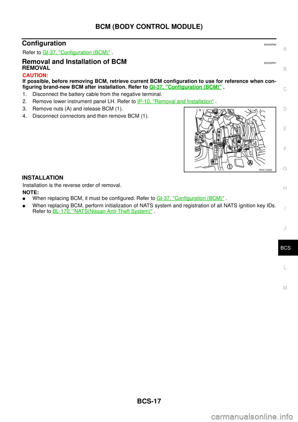
1. Disconnect the battery cable from the negative terminal.
2. Remove lower instrument panel LH. Refer toIP-10, "
Removal and Installation".
3. Remove nuts (A) and release BCM (1).
4. Disconnect connectors and then remove BCM (1).
INSTALLATION
Installation is the reverse order of removal.
NOTE:
lWhen replacing BCM, it must be configured. Refer toGI-37, "Configuration (BCM)".
lWhen replacing BCM, perform initialization of NATS system and registration of all NATS ignition key IDs.
Refer toBL-170, "
NATS(Nissan Anti-Theft System)".
PKIC1222E
Page 586 of 3171

BL-2
Model) ..................................................................... 51
Check RH and LH Rear Door Lock Actuator Switch... 51
Check Door Lock/Unlock Switch ............................ 52
Check Door Lock/Unlock Switch Indicator .............. 53
POWER DOOR LOCK — SUPER LOCK — ............ 55
Component Parts and Harness Connector Location... 55
KING CAB ........................................................... 55
DOUBLE CAB ..................................................... 56
System Description ................................................. 57
OUTLINE ............................................................. 58
OPERATION ........................................................ 58
CAN Communication System Description .............. 59
CAN Communication Unit ....................................... 59
Schematic ............................................................... 60
Wiring Diagram —D/LOCK— ................................. 61
Terminals and Reference Value for BCM ................ 69
CONSULT-II Function (BCM) .................................. 70
CONSULT-II BASIC OPERATION PROCEDURE
... 70
CONSULT-II APPLICATION ITEMS .................... 71
Work Flow ............................................................... 72
Trouble Diagnoses Chart by Symptom ................... 72
Check Power Supply and Ground Circuit ............... 73
Check Door Switch ................................................. 74
CHECK DOOR SWITCH (DOUBLE CAB) .......... 74
CHECK DOOR SWITCH (KING CAB) ................ 76
Check Key Switch ................................................... 78
Check Front Door Lock Actuator (Driver Side) ....... 80
Check Front Door Lock Actuator (Passenger Side)... 81
Check Front Door Lock Actuator Switch ................. 81
Check Rear Door Lock Actuator LH (Double Cab
Models) ................................................................... 82
Check Rear Door Lock Actuator RH (Double Cab
Models) ................................................................... 82
Check RH and LH Rear Door Lock Actuator Switch
(Double Cab Models) .............................................. 83
Check Super Lock Actuator (Driver Side) ............... 83
Check Super Lock Actuator (Passenger Side) ....... 84
Check Super Lock Actuator (Rear LH) ................... 84
Check Super Lock Actuator (Rear RH) .................. 85
Check Door Lock/Unlock Switch ............................ 86
Check Door Lock/Unlock Switch Indicator .............. 87
MULTI-REMOTE CONTROL SYSTEM ..................... 89
Component Parts and Harness Connector Location... 89
KING CAB ........................................................... 89
DOUBLE CAB ..................................................... 90
System Description ................................................. 91
INPUTS ............................................................... 91
OPERATING PROCEDURE ................................ 91
CAN Communication System Description .............. 92
Wiring Diagram — MULTI — For LHD Models ....... 93
Wiring Diagram — MULTI — For RHD Models ...... 97
Terminals and Reference Value for BCM ..............101
CONSULT-II Function (BCM) ................................102
CONSULT-II Inspection Procedure .......................102
“MULTI REMOTE ENT” .....................................102
CONSULT-II Application Items .............................103
“MULTI REMOTE ENT” .....................................103
Trouble Diagnosis Procedure ...............................104Trouble Diagnosis Chart by Symptom ..................105
Check Keyfob Battery and Function .....................106
Check ACC Switch ................................................107
Check Door Switch ...............................................108
CHECK DOOR SWITCH (DOUBLE CAB) .........108
CHECK DOOR SWITCH (KING CAB) ...............110
Check Key Switch .................................................113
Check Hazard Function ........................................114
Check Map Lamp and Ignition Keyhole Illumination
Function ................................................................114
ID Code Entry Procedure ......................................115
KEYFOB ID SET UP ..........................................115
CONSULT-II INSPECTION PROCEDURE ........115
Remote Controller Battery Replacement ..............116
DOOR ......................................................................117
Fitting Adjustment (King Cab) ...............................117
FRONT DOOR ...................................................118
REAR DOOR .....................................................118
STRIKER ADJUSTMENT ..................................118
Fitting Adjustment (Double Cab) ...........................119
FRONT DOOR ...................................................120
REAR DOOR .....................................................120
STRIKER ADJUSTMENT ..................................120
Removal and Installation of Front Door ................120
REMOVAL ..........................................................120
INSTALLATION ..................................................121
Removal and Installation of Rear Door (King Cab).121
REMOVAL ..........................................................121
INSTALLATION ..................................................122
Removal and Installation of Rear Door (Double Cab)
.123
REMOVAL ..........................................................123
INSTALLATION ..................................................123
Removal and Installation of Door Weather-strip
(King Cab) .............................................................124
REMOVAL ..........................................................124
INSTALLATION ..................................................124
Removal and Installation of Door Weather-strip
(Double Cab) .........................................................125
REMOVAL ..........................................................125
INSTALLATION ..................................................125
FRONT DOOR LOCK ..............................................126
Removal and Installation .......................................126
REMOVAL ..........................................................126
INSTALLATION ..................................................129
REAR DOOR LOCK ................................................130
Removal and Installation of Rear Door Lock (King
Cab) ......................................................................130
REMOVAL ..........................................................130
INSTALLATION ..................................................131
Removal and Installation of Rear Door Lock (Double
Cab) ......................................................................132
REMOVAL ..........................................................132
INSTALLATION ..................................................134
TAIL GATE ...............................................................135
Component Parts Location ...................................135
FUEL FILLER LID OPENER ...................................136
Removal and Installation of Fuel Filler Lid ............136
REMOVAL ..........................................................136
Page 607 of 3171
POWERDOORLOCKSYSTEM
BL-23
C
D
E
F
G
H
J
K
L
MA
B
BL
System DescriptionEIS00D7R
Power is supplied at all times
lthrough 50A fusible link (letterG, located in the fuse and fusible link box)
lto BCM terminal 57
lthrough 10A fuse [No. 21, located in the fuse block (J/B)]
lto BCM terminal 41
lthrough 10A fuse [No. 22, located in the fuse block (J/B)]
lto key switch terminal 2.
When key switch is ON, power is supplied
lthrough key switch terminal 1
lto BCM terminal 5.
When ignition switch is in ON or START position
lthrough 10A fuse [No. 1, located in the fuse block (J/B)]
lto BCM terminal 3.
Ground is supplied
lto BCM terminal 55
lthrough body grounds M21, M80 and M83.
Door switch operation
When front door switch (driver side) is ON (door is OPEN), ground is supplied
lto BCM terminal 15
lthrough front door switch (driver side) terminal 2
lthrough front door switch (driver side) case ground.
When front door switch (passenger side) is ON (door is OPEN), ground is supplied
lto BCM terminal 14
lthrough front door switch (passenger side) terminal 2
lthrough front door switch (passenger side) case ground.
When rear door switch LH is ON (door is OPEN), ground is supplied (Double cab model)
lto BCM terminal 16
lthrough rear door switch LH terminal 2
lthrough rear door switch LH case ground.
When rear door switch RH is ON (door is OPEN), ground is supplied (Double cab model)
lto BCM terminal 12
lthrough rear door switch RH terminal 2
lthrough rear door switch RH case ground.
Key cylinder switch operation (Without multi-remote control system)
When key cylinder is turned to lock position, ground is supplied
lthrough BCM terminal 34
lto key cylinder switch (driver and passenger side) terminals 4
lthrough key cylinder switch (driver and passenger side) terminals 5
lthrough body ground M21, M80 and M83
then all doors are locked.
When key cylinder is turned to unlock position, ground is supplied
lthrough BCM terminal 32
lto key cylinder switch (driver and passenger side) terminal 6
lthrough key cylinder switch (driver and passenger side) terminal 5
lthrough body ground M21, M80 and M83
then all doors are unlocked.
Power door lock operation with door lock/unlock switch
When doors are lock by door lock/unlock switch, ground is supplied