Page 608 of 3171

BL-24
POWER DOOR LOCK SYSTEM
lto BCM terminal 34
lthrough door lock /unlock switch terminals 1 and 3
lthrough body grounds M21, M80 and M83.
then all doors are locked.
When door lock/unlock switch is locked, ground is supplied
lthrough BCM terminal 56
lthrough all door actuators terminal 3
lthrough all door lock actuators terminal 2
lthrough back door lock actuator terminals 1 and 3
lto BCM terminals 54 and 60.
then all doors actuators are locked
Power door unlock operation with door lock/unlock switch
When doors are unlock by door lock/unlock switch, ground is supplied
lto BCM terminal 32
lthrough door lock/unlock switch terminals 2 and 3
lthrough body grounds M21, M80 and M83.
then all doors are locked.
When door lock/unlock switch is unlocked, ground is supplied
lthrough BCM terminals 54 and 60
lthrough all door lock actuators terminal 2
lthrough all door lock actuators terminal 3
lthen all door actuators are unlock
lto BCM terminal 56.
Door lock/unlock switch indicator operation
When door lock/unlock switch is locked, all doors are locked, door lock/unlock switch indicator is on, and
ground is supplied
lto BCM terminal 17
lthrough door lock/unlock switch terminals 5 and 3
lthrough body grounds M21, M80 and M83.
OUTLINE
Function Available by Operating the Door Lock/Unlock Switch
lOperating the door lock/unlock switch to “LOCK” will lock all doors.
lOperating the door lock/unlock switch to “UNLOCK” will unlock all doors.
NOTE:
Unlock via the interior door handles and door lock/unlock switch is always possible.
Door Lock Warning Function
Under following conditions lock actuators will not respond and buzzer warning will beeps while pressing door
lock/unlock switch in LOCK direction.
lIgnition switch is turned OFF
lMechanical key is out of ignition key cylinder
lDoor is opened (except driver side door)
Key Reminder Function
Under following conditions lock actuators will lock the door once, but then immediately unlock all doors and
buzzer warning will beeps while pressing door lock/unlock switch in LOCK direction.
lIgnition switch is turned OFF
lMechanical key is inserted in ignition key cylinder
lDriver side door is opened
Door Lock/Unlock Switch Indicator
The Door lock/unlock switch indicates door lock status. The indicator will illuminates when a lock operation is
accomplish, during this state, if any door is open, the indicator will turn OFF.
Page 609 of 3171

POWERDOORLOCKSYSTEM
BL-25
C
D
E
F
G
H
J
K
L
MA
B
BL
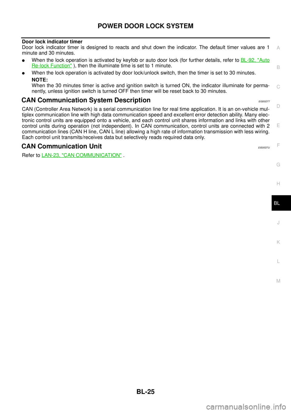
Door lock indicator timer
Door lock indicator timer is designed to reacts and shut down the indicator. The default timer values are 1
minute and 30 minutes.
lWhen the lock operation is activated by keyfob or auto door lock (for further details, refer toBL-92, "Auto
Re-lock Function"), then the illuminate time is set to 1 minute.
lWhen the lock operation is activated by door lock/unlock switch, then the timer is set to 30 minutes.
NOTE:
When the 30 minutes timer is active and ignition switch is turned ON, the indicator illuminate for perma-
nently, unless ignition switch is turned OFF then timer will be reset back to 30 minutes.
CAN Communication System DescriptionEIS00D7T
CAN (Controller Area Network) is a serial communication line for real time application. It is an on-vehicle mul-
tiplex communication line with high data communication speed and excellent error detection ability. Many elec-
tronic control units are equipped onto a vehicle, and each control unit shares information and links with other
control units during operation (not independent). In CAN communication, control units are connected with 2
communication lines (CAN H line, CAN L line) allowing a high rate of information transmission with less wiring.
Each control unit transmits/receives data but selectively reads required data only.
CAN Communication UnitEIS00D7U
Refer toLAN-23, "CAN COMMUNICATION".
Page 618 of 3171
![NISSAN NAVARA 2005 Repair Workshop Manual BL-34
POWER DOOR LOCK SYSTEM
Terminals and Reference Value for BCM
EIS00D7Z
*: Double cab modelTERMI-
NALWIRE
COLORITEM CONDITIONVOLTAGE [V]
(Approx.)
3 Y Ignition switch Ignition switch ON Battery vo NISSAN NAVARA 2005 Repair Workshop Manual BL-34
POWER DOOR LOCK SYSTEM
Terminals and Reference Value for BCM
EIS00D7Z
*: Double cab modelTERMI-
NALWIRE
COLORITEM CONDITIONVOLTAGE [V]
(Approx.)
3 Y Ignition switch Ignition switch ON Battery vo](/manual-img/5/57362/w960_57362-617.png)
BL-34
POWER DOOR LOCK SYSTEM
Terminals and Reference Value for BCM
EIS00D7Z
*: Double cab modelTERMI-
NALWIRE
COLORITEM CONDITIONVOLTAGE [V]
(Approx.)
3 Y Ignition switch Ignition switch ON Battery voltage
5RKeyswitchKey switch ON Battery voltage
Key switch OFF 0
12 L Rear door switch RH* ON (Door is opened)®OFF (Door is closed) 0®Battery voltage
14 LGFront door switch
(Passenger side)ON (Door is opened)®OFF (Door is closed) 0®Battery voltage
15 SBFront door switch
(Driver side)ON (Door is opened)®OFF (Door is closed) 0®Battery voltage
16 P Rear door switch LH* ON (Door is opened)®OFF (Door is closed) 0®Battery voltage
17 WDoor lock/unlock switch indi-
catorAll door closedLock operation
(Illuminates)Battery voltage
Other than above 0
21 P CAN-L — —
22 L CAN-H — —
32 GR Door lock/unlock switch All door closedUnlock 0
Other than above 5
34 O Door lock/unlock switch All door closedLock 0
Other than above 5
41 YPower switch
(Fuse)— Battery voltage
54 GPassenger and rear door lock
actuators*1 (unlock)Door lock/unlock switch (Free®Lock) 0®Battery voltage®0
55 B Ground — 0
56 V All door lock actuators (lock) Door lock/unlock switch (Free®Lock) 0®Battery voltage®0
57 WPower source
(Fusible link)— Battery voltage
60 GDriver door lock actuator
(unlock)Door lock/unlock switch (Free®Lock) 0®Battery voltage®0
Page 619 of 3171
POWERDOORLOCKSYSTEM
BL-35
C
D
E
F
G
H
J
K
L
MA
B
BL
CONSULT-II Function (BCM)EIS00D80
CONSULT-II and display each diagnostic item using the diagnostic test modes shown following.
CONSULT-II BASIC OPERATION PROCEDURE
CAUTION:
If CONSULT-II is used with no connection of CONSULT-II CONVERTER, malfunctions might be
detected in self-diagnosis depending on control unit which carry out CAN communication.
1. Turn ignition switch “OFF”.
2. Connect “CONSULT-II” and “CONSULT-II CONVERTER” to
data link connector.
3. Turn ignition switch “ON”.
4. Touch “START (NISSAN BASED VHCL)”.
5. Touch “BCM” on “SELECT SYSTEM” screen.
If “BCM” is not indicated, go toGI-50, "
CONSULT-II Data Link
Connector (DLC) Circuit".
BCM diagnosis partInspection item, self-diagnosis
modeContent
DOOR LOCKWORK SUPPORT Changes the setting for each function.
DATA MONITOR Displays the input data of BCM in real time.
ACTIVE TEST Give a drive signals to load to check the operation.
BBIA0538E
BCIA0029E
BCIA0030E
Page 620 of 3171

BL-36
POWER DOOR LOCK SYSTEM
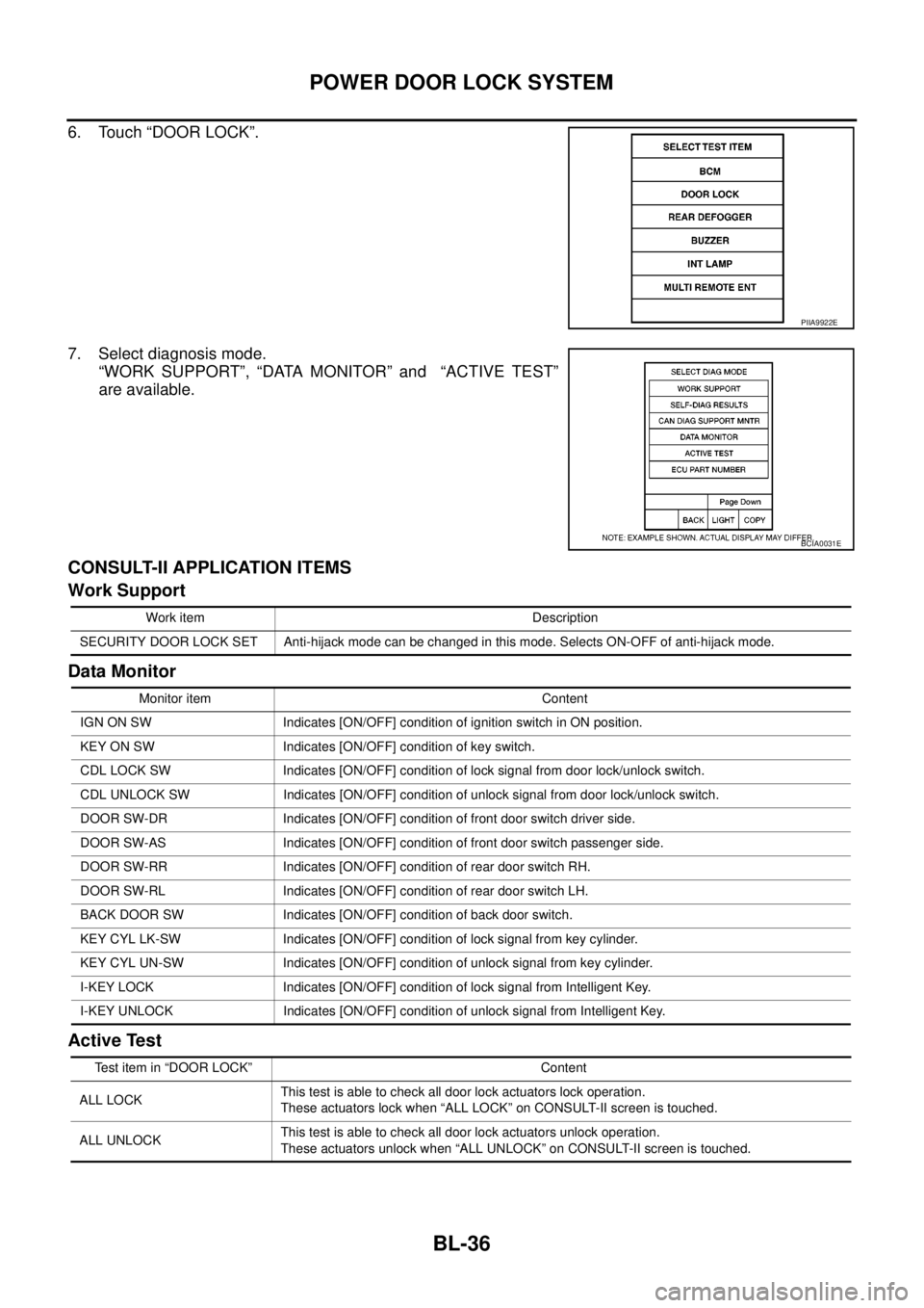
6. Touch “DOOR LOCK”.
7. Select diagnosis mode.
“WORK SUPPORT”, “DATA MONITOR” and “ACTIVE TEST”
are available.
CONSULT-II APPLICATION ITEMS
Work Support
Data Monitor
Active Test
PIIA9922E
BCIA0031E
Work item Description
SECURITY DOOR LOCK SET Anti-hijack mode can be changed in this mode. Selects ON-OFF of anti-hijack mode.
Monitor item Content
IGN ON SW Indicates [ON/OFF] condition of ignition switch in ON position.
KEY ON SW Indicates [ON/OFF] condition of key switch.
CDL LOCK SW Indicates [ON/OFF] condition of lock signal from door lock/unlock switch.
CDL UNLOCK SW Indicates [ON/OFF] condition of unlock signal from door lock/unlock switch.
DOOR SW-DR Indicates [ON/OFF] condition of front door switch driver side.
DOOR SW-AS Indicates [ON/OFF] condition of front door switch passenger side.
DOOR SW-RR Indicates [ON/OFF] condition of rear door switch RH.
DOOR SW-RL Indicates [ON/OFF] condition of rear door switch LH.
BACK DOOR SW Indicates [ON/OFF] condition of back door switch.
KEY CYL LK-SW Indicates [ON/OFF] condition of lock signal from key cylinder.
KEY CYL UN-SW Indicates [ON/OFF] condition of unlock signal from key cylinder.
I-KEY LOCK Indicates [ON/OFF] condition of lock signal from Intelligent Key.
I-KEY UNLOCK Indicates [ON/OFF] condition of unlock signal from Intelligent Key.
Test item in “DOOR LOCK” Content
ALL LOCKThis test is able to check all door lock actuators lock operation.
These actuators lock when “ALL LOCK” on CONSULT-II screen is touched.
ALL UNLOCKThis test is able to check all door lock actuators unlock operation.
These actuators unlock when “ALL UNLOCK” on CONSULT-II screen is touched.
Page 622 of 3171
BL-38
POWER DOOR LOCK SYSTEM
2.CHECK POWER SUPPLY CIRCUIT
1. Turn ignition switch OFF.
2. Disconnect BCM connector.
3. Check voltage between BCM and ground.
OK or NG
OK >> GO TO 3.
NG >> Repair or replace BCM power supply circuit.
3.CHECK GROUND CIRCUIT
Check continuity between BCM connector M44 terminal 55 and
ground.
OK or NG
OK >> BCM power supply and ground circuit is OK.
NG >> Repair or replace BCM ground circuit.
ConnectorTerminals Ignition switch position
(+) (-) OFF ACC ON
M42 3
Ground0V 0VBattery
voltage
M43 41
Battery
voltageBattery
voltageBattery
voltage
M44 57
MIIB0823E
55 – Ground : Continuity should exist.
MIIB0824E
Page 623 of 3171

POWERDOORLOCKSYSTEM
BL-39
C
D
E
F
G
H
J
K
L
MA
B
BL
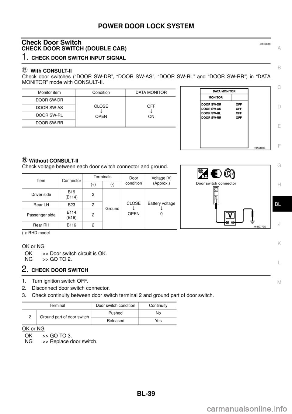
Check Door SwitchEIS00D85
CHECK DOOR SWITCH (DOUBLE CAB)
1.CHECK DOOR SWITCH INPUT SIGNAL
With CONSULT-II
Check door switches (“DOOR SW-DR”, “DOOR SW-AS”, “DOOR SW-RL” and “DOOR SW-RR”) in “DATA
MONITOR” mode with CONSULT-II.
Without CONSULT-II
Check voltage between each door switch connector and ground.
( ): RHD model
OK or NG
OK >> Door switch circuit is OK.
NG >> GO TO 2.
2.CHECK DOOR SWITCH
1. Turn ignition switch OFF.
2. Disconnect door switch connector.
3. Check continuity between door switch terminal 2 and ground part of door switch.
OK or NG
OK >> GO TO 3.
NG >> Replace door switch.
Monitor item Condition DATA MONITOR
DOOR SW-DR
CLOSE
¯
OPENOFF
¯
ON DOOR SW-AS
DOOR SW-RL
DOOR SW-RR
PIIA6469E
Item ConnectorTerminals
Door
conditionVo l ta g e [V ]
(Approx.)
(+) (-)
Driver sideB19
(B114)2
GroundCLOSE
¯
OPENBattery voltage
¯
0 Rear LH B23 2
Passenger sideB114
(B19)2
Rear RH B116 2
MIIB0773E
Terminal Door switch condition Continuity
2 Ground part of door switchPushed No
Released Yes
Page 626 of 3171

BL-42
POWER DOOR LOCK SYSTEM
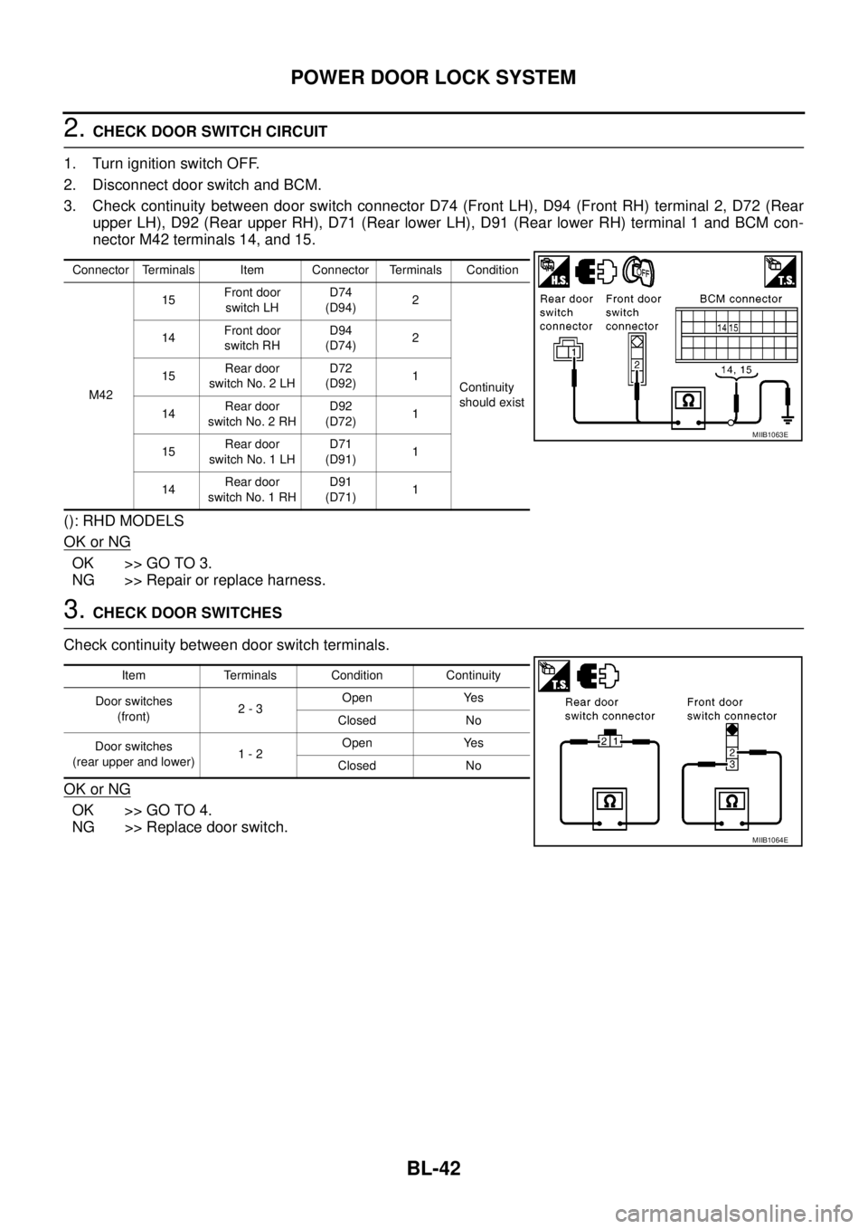
2.CHECK DOOR SWITCH CIRCUIT
1. Turn ignition switch OFF.
2. Disconnect door switch and BCM.
3. Check continuity between door switch connector D74 (Front LH), D94 (Front RH) terminal 2, D72 (Rear
upper LH), D92 (Rear upper RH), D71 (Rear lower LH), D91 (Rear lower RH) terminal 1 and BCM con-
nector M42 terminals 14, and 15.
(): RHD MODELS
OK or NG
OK >> GO TO 3.
NG >> Repair or replace harness.
3.CHECK DOOR SWITCHES
Check continuity between door switch terminals.
OK or NG
OK >> GO TO 4.
NG >> Replace door switch.
Connector Terminals Item Connector Terminals Condition
M4215Front door
switch LHD74
(D94)2
Continuity
should exist 14Front door
switch RHD94
(D74)2
15Rear door
switch No. 2 LHD72
(D92)1
14Rear door
switch No. 2 RHD92
(D72)1
15Rear door
switch No. 1 LHD71
(D91)1
14Rear door
switch No. 1 RHD91
(D71)1
MIIB1063E
Item Terminals Condition Continuity
Door switches
(front)2-3Open Yes
Closed No
Door switches
(rear upper and lower)1-2Open Yes
Closed No
MIIB1064E