Page 388 of 3171

ATC-54
TROUBLE DIAGNOSIS
19 GR Power supply for BAT - - Battery voltage
20 B Ground - - 0V
21 V Mode door motor feedback ON - 0 - 5V
22 SB Air mix door motor (Driver) feedback ON - 0 - 5V
23 G Sensor power ON - 5V
26 P Sensor return ON - 0V
27 R In-vehicle sensor signal ON - 0 - 5V
28 W Ambient sensor ON - 0 - 5V
29 G Optical sensor (Driver) ON - 0 - 5V
31 PPTC heater relay 1
(LHD models)ONRelay ON Battery voltage
Relay OFF 0V
32 V Variable blower control ON - 0 - 5V
33 BR In-vehicle sensor motor (+) ON - Battery voltage
34 O In-vehicle sensor motor (-) ON - 0V
35 LG Fan ON signalON Blower switch OFF 5V
ON Blower switch ON 0V
36 SBAir mix door motor (Passenger)
feedbackON - 0 - 5V
37 GR Optical sensor (Passenger) ON - 0 - 5V
38 B Blower request ONBlower motor OFF Battery voltage
Blower motor ON 0V
40 LGPTC heater relay 2
(LHD models)ONRelay ON Battery voltage
Relay OFF 0V
41 L CAN-H ON - 0 - 5V
42 P CAN-L ON - 0 - 5V
43 BRPTC heater relay 3
(LHD models)ONRelay ON Battery voltage
Relay OFF 0V
44 R Mirror heater (LHD models) ONHeater OFF 0V
Heater ON Battery voltage Te r m i -
nal No.Wire
colorItemIgnition
switchConditionVoltage (V)
(Approx.)
Page 391 of 3171

TROUBLE DIAGNOSIS
ATC-57
C
D
E
F
G
H
I
K
L
MA
B
AT C
Operational CheckEJS006BH
The purpose of the operational check is to confirm that the system operates properly.
CHECKING MEMORY FUNCTION
1. Set the temperature to 32°C(90°F).
2. Turn blower control dial counterclockwise until system shuts
OFF.
3. Turn ignition switch OFF.
4. Turn ignition switch ON.
5. Press the AUTO switch.
6. Confirm that the set temperature remains at previous tempera-
ture.
7. Turn blower control dial counterclockwise until system shuts
OFF.
If NG, go to trouble diagnosis procedure forATC-104, "
Memory
Function".
If OK, continue with next check.
CHECKING BLOWER
1. Press the AUTO switch. Blower should operate on low speed.
The blower symbol should have one blade lit (on display).
2. Turn the blower control dial again, and continue checking blower
speed and blower symbol until all speeds are checked.
3. Leave blower on MAX speed.
If NG, go to trouble diagnosis procedure forAT C - 8 2 , "
DIAGNOSTIC
PROCEDURE FOR BLOWER MOTOR".
If OK, continue with next check.Conditions : Engine running and at normal operating temperature
MJIB0335E
MJIB0336E
MJIB0335E
MJIB0337E
Page 396 of 3171

ATC-62
TROUBLE DIAGNOSIS
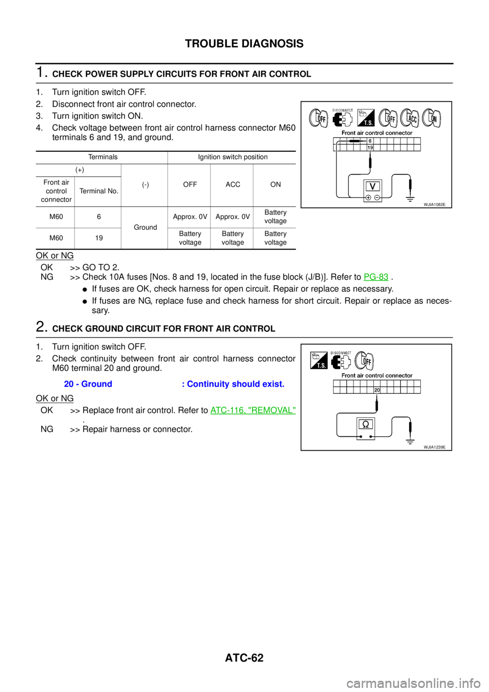
1.CHECK POWER SUPPLY CIRCUITS FOR FRONT AIR CONTROL
1. Turn ignition switch OFF.
2. Disconnect front air control connector.
3. Turn ignition switch ON.
4. Check voltage between front air control harness connector M60
terminals 6 and 19, and ground.
OK or NG
OK >> GO TO 2.
NG >> Check 10A fuses [Nos. 8 and 19, located in the fuse block (J/B)]. Refer toPG-83
.
lIf fuses are OK, check harness for open circuit. Repair or replace as necessary.
lIf fuses are NG, replace fuse and check harness for short circuit. Repair or replace as neces-
sary.
2.CHECK GROUND CIRCUIT FOR FRONT AIR CONTROL
1. Turn ignition switch OFF.
2. Check continuity between front air control harness connector
M60 terminal 20 and ground.
OK or NG
OK >> Replace front air control. Refer toAT C - 11 6 , "REMOVAL"
.
NG >> Repair harness or connector.
Terminals Ignition switch position
(+)
(-) OFF ACC ON Front air
control
connectorTerminal No.
M60 6
GroundApprox. 0V Approx. 0VBattery
voltage
M60 19Battery
voltageBattery
voltageBattery
voltage
WJIA1082E
20 - Ground : Continuity should exist.
WJIA1239E
Page 399 of 3171

TROUBLE DIAGNOSIS
ATC-65
C
D
E
F
G
H
I
K
L
MA
B
AT C
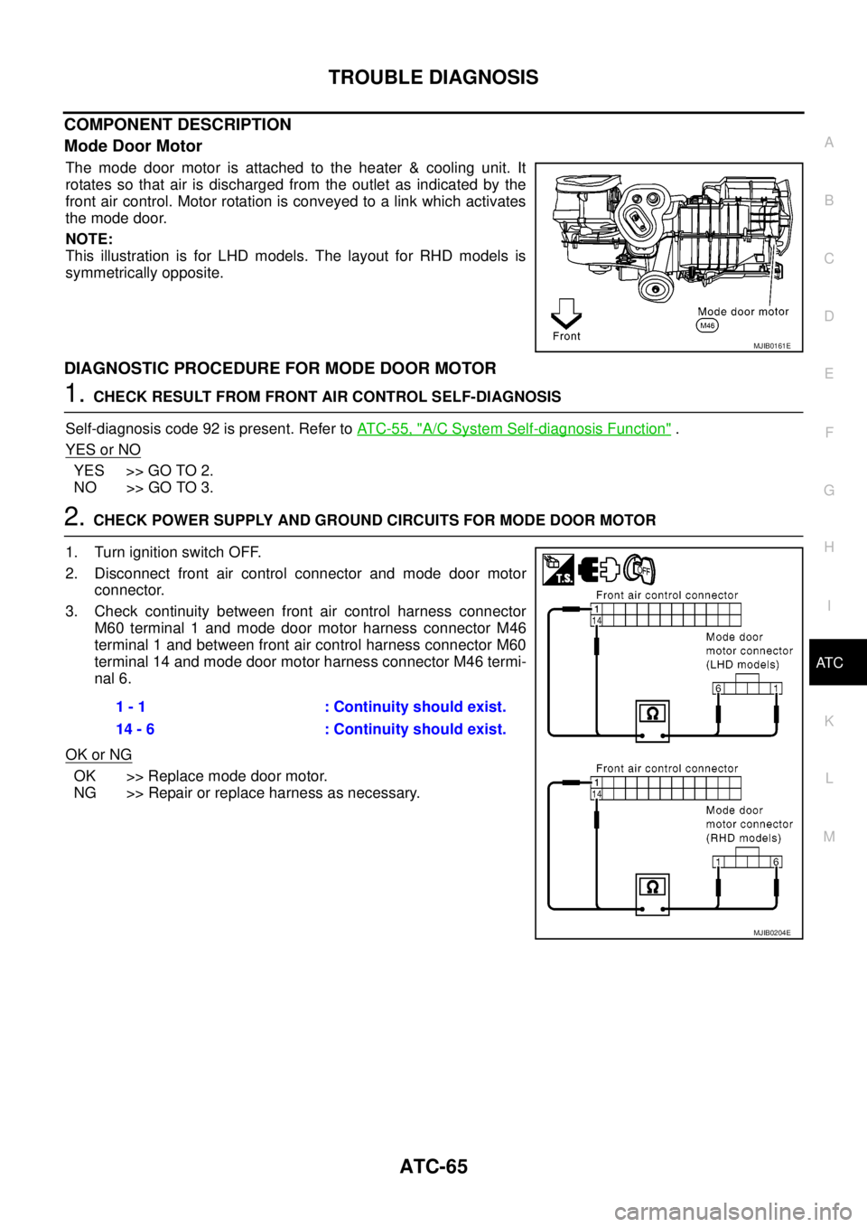
COMPONENT DESCRIPTION
Mode Door Motor
The mode door motor is attached to the heater & cooling unit. It
rotates so that air is discharged from the outlet as indicated by the
front air control. Motor rotation is conveyed to a link which activates
themodedoor.
NOTE:
This illustration is for LHD models. The layout for RHD models is
symmetrically opposite.
DIAGNOSTIC PROCEDURE FOR MODE DOOR MOTOR
1.CHECK RESULT FROM FRONT AIR CONTROL SELF-DIAGNOSIS
Self-diagnosis code 92 is present. Refer toAT C - 5 5 , "
A/C System Self-diagnosis Function".
YES or NO
YES >> GO TO 2.
NO >> GO TO 3.
2.CHECK POWER SUPPLY AND GROUND CIRCUITS FOR MODE DOOR MOTOR
1. Turn ignition switch OFF.
2. Disconnect front air control connector and mode door motor
connector.
3. Check continuity between front air control harness connector
M60 terminal 1 and mode door motor harness connector M46
terminal 1 and between front air control harness connector M60
terminal 14 and mode door motor harness connector M46 termi-
nal 6.
OK or NG
OK >> Replace mode door motor.
NG >> Repair or replace harness as necessary.
MJIB0161E
1 - 1 : Continuity should exist.
14 - 6 : Continuity should exist.
MJIB0204E
Page 400 of 3171
ATC-66
TROUBLE DIAGNOSIS
3.CHECK PBR REFERENCE SIGNAL VOLTAGE
1. Turn ignition switch OFF.
2. Disconnect the mode door motor connector.
3. Turn ignition switch ON.
4. Check voltage between mode door motor harness connector
M46 terminal 3 and ground.
OK or NG
OK >> GO TO 5.
NG >> GO TO 4.
4.CHECK PBR REFERENCE VOLTAGE CIRCUIT BETWEEN MODE DOOR AND FRONT AIR CONTROL
1. Turn ignition switch OFF.
2. Disconnect the front air control connector.
3. Check continuity between mode door motor harness connector
M46 terminal 3 and front air control harness connector M60 ter-
minal 23.
OK or NG
OK >> Replace front air control. Refer toAT C - 11 6 , "REMOVAL"
.
NG >> Repair or replace harness as necessary.3 - Ground : Approx. 5V
MJIB0205E
3 - 23 : Continuity should exist.
MJIB0206E
Page 401 of 3171

TROUBLE DIAGNOSIS
ATC-67
C
D
E
F
G
H
I
K
L
MA
B
AT C
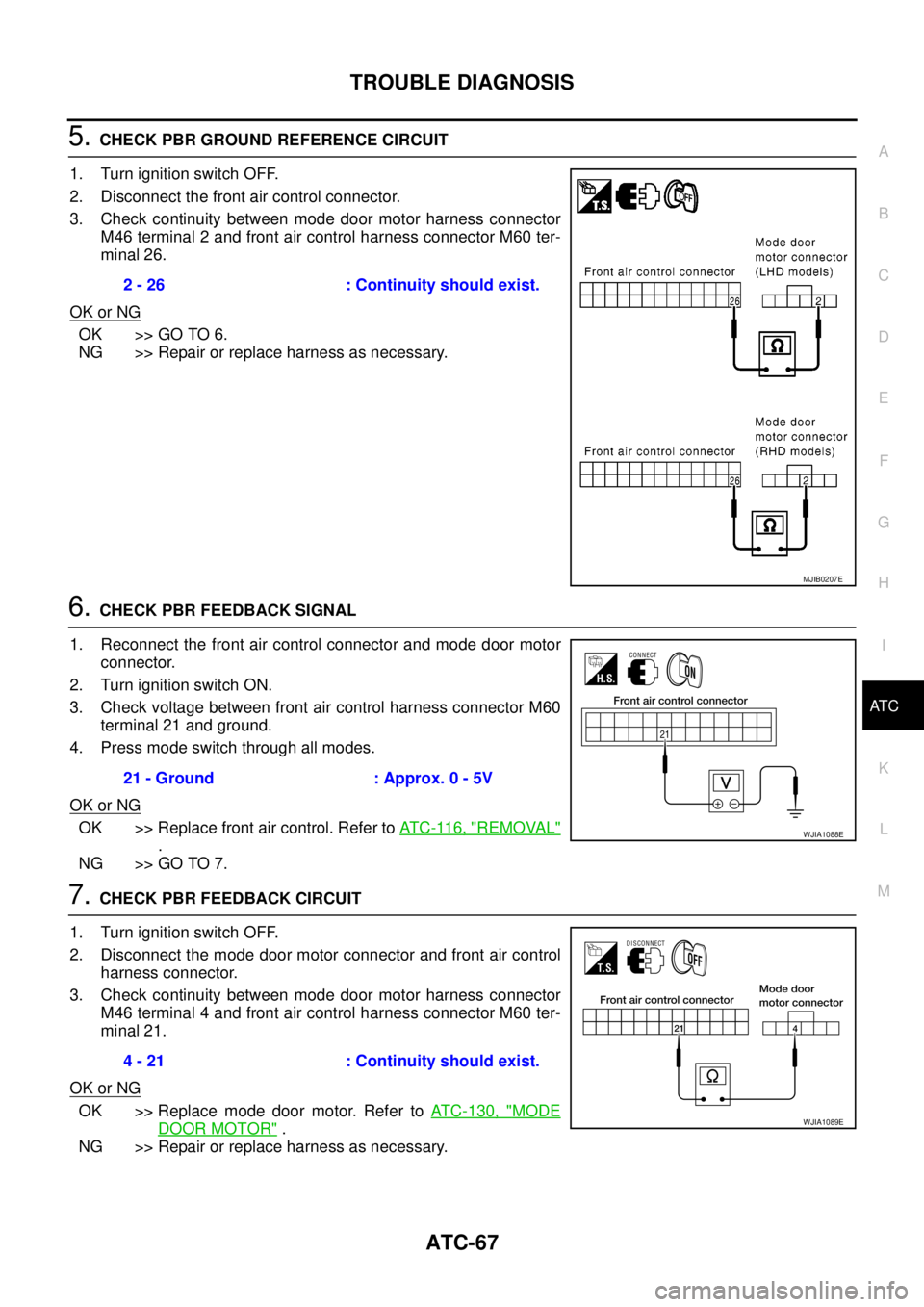
5.CHECK PBR GROUND REFERENCE CIRCUIT
1. Turn ignition switch OFF.
2. Disconnect the front air control connector.
3. Check continuity between mode door motor harness connector
M46 terminal 2 and front air control harness connector M60 ter-
minal 26.
OK or NG
OK >> GO TO 6.
NG >> Repair or replace harness as necessary.
6.CHECK PBR FEEDBACK SIGNAL
1. Reconnect the front air control connector and mode door motor
connector.
2. Turn ignition switch ON.
3. Check voltage between front air control harness connector M60
terminal 21 and ground.
4. Press mode switch through all modes.
OK or NG
OK >> Replace front air control. Refer toAT C - 11 6 , "REMOVAL"
.
NG >> GO TO 7.
7.CHECK PBR FEEDBACK CIRCUIT
1. Turn ignition switch OFF.
2. Disconnect the mode door motor connector and front air control
harness connector.
3. Check continuity between mode door motor harness connector
M46 terminal 4 and front air control harness connector M60 ter-
minal 21.
OK or NG
OK >> Replace mode door motor. Refer toATC-130, "MODE
DOOR MOTOR".
NG >> Repair or replace harness as necessary.2 - 26 : Continuity should exist.
MJIB0207E
21 - Ground : Approx. 0 - 5V
WJIA1088E
4 - 21 : Continuity should exist.
WJIA1089E
Page 405 of 3171

TROUBLE DIAGNOSIS
ATC-71
C
D
E
F
G
H
I
K
L
MA
B
AT C
DIAGNOSTIC PROCEDURE FOR AIR MIX DOOR MOTOR (DRIVER)
1.CHECK RESULT FROM FRONT AIR CONTROL SELF-DIAGNOSIS
Self-diagnosis code 22 is present. Refer toAT C - 5 5 , "
A/C System Self-diagnosis Function".
YES or NO
YES >> GO TO 2.
NO >> GO TO 3.
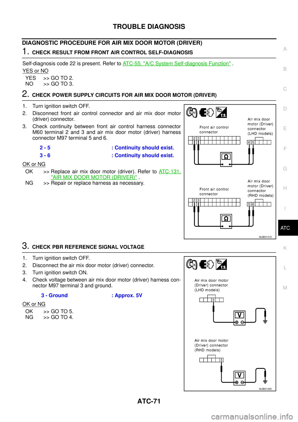
2.CHECK POWER SUPPLY CIRCUITS FOR AIR MIX DOOR MOTOR (DRIVER)
1. Turn ignition switch OFF.
2. Disconnect front air control connector and air mix door motor
(driver) connector.
3. Check continuity between front air control harness connector
M60 terminal 2 and 3 and air mix door motor (driver) harness
connector M97 terminal 5 and 6.
OK or NG
OK >> Replace air mix door motor (driver). Refer toATC-131,
"AIR MIX DOOR MOTOR (DRIVER)".
NG >> Repair or replace harness as necessary.
3.CHECK PBR REFERENCE SIGNAL VOLTAGE
1. Turn ignition switch OFF.
2. Disconnect the air mix door motor (driver) connector.
3. Turn ignition switch ON.
4. Check voltage between air mix door motor (driver) harness con-
nector M97 terminal 3 and ground.
OK or NG
OK >> GO TO 5.
NG >> GO TO 4.2 - 5 : Continuity should exist.
3 - 6 : Continuity should exist.
MJIB0101E
3 - Ground : Approx. 5V
MJIB0102E
Page 406 of 3171
ATC-72
TROUBLE DIAGNOSIS
4.CHECK PBR REFERENCE VOLTAGE CIRCUIT BETWEEN AIR MIX DOOR MOTOR (DRIVER) AND
FRONT AIR CONTROL
1. Turn ignition switch OFF.
2. Disconnect the front air control connector.
3. Check continuity between air mix door motor (driver) harness
connector M97 terminal 3 and front air control harness connec-
tor M60 terminal 23.
OK or NG
OK >> Replace front air control. Refer toAT C - 11 6 , "REMOVAL"
.
NG >> Repair or replace harness as necessary.
5.CHECK PBR GROUND REFERENCE CIRCUIT
1. Turn ignition switch OFF.
2. Disconnect the front air control connector.
3. Check continuity between air mix door motor (driver) harness
connector M97 terminal 1 and front air control harness connec-
tor M60 terminal 26.
OK or NG
OK >> GO TO 6.
NG >> Repair or replace harness as necessary.3 - 23 : Continuity should exist.
MJIB0103E
1 - 26 : Continuity should exist.
MJIB0104E