2005 MERCEDES-BENZ SPRINTER Steering wheel
[x] Cancel search: Steering wheelPage 241 of 1232
ACTIVE RESTRAINTS
The active restraints for this model include:
²Front Seat Belts- Both outboard front seating
positions are equipped with three-point seat belt sys-
tems employing a lower B-pillar mounted inertia
latch-type retractors, height-adjustable upper B-pil-
lar mounted turning loops, travelling lower seat belt
anchors secured to the outboard seat tracks, and
travelling end-release seat belt buckles secured to
the inboard seat track. The driver side front seat belt
buckle of all models includes an integral seat belt
switch that detects whether its seat belt has been
fastened.
²Rear Seat Belts- All rear seating positions are
equipped with three-point seat belt systems. Each
rear seating position belt employs an integral seat
cushion frame mounted inertia latch-type retractor, a
fixed position upper seat back frame mounted turn-
ing loop, and a fixed lower seat belt anchor secured
to the seat cushion frame. All rear seat belts have
fixed end-release seat belt buckles that are also
secured to the seat cushion frame.
PASSIVE RESTRAINTS
A Next Generation driver airbag is standard facto-
ry-installed safety equipment on this model, while a
passenger side front airbag is optional. This airbag
system is a passive, inflatable, Supplemental
Restraint System (SRS) and vehicles with this equip-
ment can be readily identified by the ªSRS - AIR-
BAGº logo molded into the driver airbag trim cover
in the center of the steering wheel and, if the vehicle
is so equipped, also into the passenger airbag door on
the instrument panel above the glove box (Fig. 2).
Vehicles with the airbag system can also be identified
by the airbag indicator, which will illuminate in the
instrument cluster for about six seconds as a bulb
test each time the ignition switch is turned to the On
position. A pyrotechnic-type seat belt tensioner is
integral to the front seat belt retractor mounted on
the lower B-pillar on the driver side, and to the pas-
senger side retractor of vehicles equipped with the
optional passenger side airbag.
The supplemental restraint system includes the
following major components, which are described in
further detail elsewhere in this service information:
²Airbag Control Module- The Airbag Control
Module (ACM) is located on a mount on the floor
panel within the driver side seat riser, beneath the
driver seat in the passenger compartment.
²Airbag (SRS) Indicator- The airbag indicator
is integral to the ElectroMechanical Instrument Clus-
ter (EMIC), which is located on the instrument panel
in front of the driver.²Clockspring- The clockspring is located near
the top of the steering column, directly beneath the
steering wheel.
²Driver Airbag- The driver airbag is located in
the center of the steering wheel, beneath the driver
airbag trim cover.
²Driver Knee Blocker- The structure of the
lower instrument panel serves as a knee blocker for
the driver.
²Passenger Airbag- The optional passenger air-
bag is located within the instrument panel, behind
the passenger airbag door on the instrument panel
above the glove box on the passenger side of the vehi-
cle.
²Passenger Knee Blocker- The structure of
the glove box door and the lower instrument panel
serve as a knee blocker for the front seat passenger.
²Seat Belt Tensioner- A seat belt tensioner is
integral to the driver side front seat belt retractor
unit, and to the passenger side front seat belt retrac-
tor unit on vehicles equipped with an optional pas-
senger airbag.
The ACM contains a central processing unit and
programming that allows it to communicate on a
serial data bus diagnostic circuit connected to the
16-way Data Link Connector (DLC) located below the
left end of the instrument panel. This method of com-
munication is used for initialization of the ACM and
for diagnosis of the SRS circuits and components
using a DRBIIItscan tool.
Hard wired circuitry connects the supplemental
restraint system components to each other through
the electrical system of the vehicle. These hard wired
circuits are integral to several wire harnesses, which
are routed throughout the vehicle and retained by
many different methods. These circuits may be con-
nected to each other, to the vehicle electrical system,
and to the supplemental restraint system compo-
nents through the use of a combination of soldered
Fig. 2 SRS Logo
VARESTRAINTS 8O - 3
RESTRAINTS (Continued)
Page 243 of 1232
WARNING
WARNINGS - RESTRAINT SYSTEM
WARNING: DURING AND FOLLOWING ANY SEAT
BELT SERVICE, CAREFULLY INSPECT ALL SEAT
BELTS, BUCKLES, MOUNTING HARDWARE,
RETRACTORS, TETHER STRAPS, AND ANCHORS
FOR PROPER INSTALLATION, OPERATION, OR
DAMAGE. REPLACE ANY BELT THAT IS CUT,
FRAYED, OR TORN. STRAIGHTEN ANY BELT THAT
IS TWISTED. TIGHTEN ANY LOOSE FASTENERS.
REPLACE ANY BELT THAT HAS A DAMAGED OR
INOPERATIVE BUCKLE OR RETRACTOR. REPLACE
ANY BELT THAT HAS A BENT OR DAMAGED
LATCH PLATE OR ANCHOR PLATE. NEVER
ATTEMPT TO REPAIR A SEAT BELT COMPONENT.
ALWAYS REPLACE DAMAGED OR FAULTY SEAT
BELT COMPONENTS WITH THE CORRECT, NEW
AND UNUSED REPLACEMENT PARTS LISTED IN
THE DAIMLERCHRYSLER MOPAR PARTS CATA-
LOG.
WARNING: ON VEHICLES EQUIPPED WITH AIR-
BAGS, DISABLE THE SUPPLEMENTAL RESTRAINT
SYSTEM BEFORE ATTEMPTING ANY STEERING
WHEEL, STEERING COLUMN, DRIVER AIRBAG,
PASSENGER AIRBAG, SEAT BELT TENSIONER, OR
INSTRUMENT PANEL COMPONENT DIAGNOSIS OR
SERVICE. DISCONNECT AND ISOLATE THE BAT-
TERY NEGATIVE (GROUND) CABLE, THEN WAIT
TWO MINUTES FOR THE SYSTEM CAPACITOR TO
DISCHARGE BEFORE PERFORMING FURTHER
DIAGNOSIS OR SERVICE. THIS IS THE ONLY SURE
WAY TO DISABLE THE SUPPLEMENTAL
RESTRAINT SYSTEM. FAILURE TO TAKE THE
PROPER PRECAUTIONS COULD RESULT IN ACCI-
DENTAL AIRBAG DEPLOYMENT AND POSSIBLE
PERSONAL INJURY.
WARNING: ON VEHICLES EQUIPPED WITH AIR-
BAGS, BEFORE PERFORMING ANY WELDING
OPERATIONS DISCONNECT AND ISOLATE THE
BATTERY NEGATIVE (GROUND) CABLE AND DIS-
CONNECT ALL WIRE HARNESS CONNECTORS
FROM THE AIRBAG CONTROL MODULE (ACM).
FAILURE TO TAKE THE PROPER PRECAUTIONS
COULD RESULT IN ACCIDENTAL AIRBAG DEPLOY-
MENT AND OTHER POSSIBLE DAMAGE TO THE
SUPPLEMENTAL RESTRAINT SYSTEM CIRCUITS
AND COMPONENTS.
WARNING: AN AIRBAG INFLATOR UNIT MAY CON-
TAIN SODIUM AZIDE AND POTASSIUM NITRATE.THESE MATERIALS ARE POISONOUS AND
EXTREMELY FLAMMABLE. CONTACT WITH ACID,
WATER, OR HEAVY METALS MAY PRODUCE HARM-
FUL AND IRRITATING GASES (SODIUM HYDROXIDE
IS FORMED IN THE PRESENCE OF MOISTURE) OR
COMBUSTIBLE COMPOUNDS. AN AIRBAG INFLA-
TOR UNIT MAY ALSO CONTAIN A GAS CANISTER
PRESSURIZED TO OVER 2500 PSI. DO NOT
ATTEMPT TO DISMANTLE AN AIRBAG UNIT OR
TAMPER WITH ITS INFLATOR. DO NOT PUNCTURE,
INCINERATE, OR BRING INTO CONTACT WITH
ELECTRICITY. DO NOT STORE AT TEMPERATURES
EXCEEDING 93É C (200É F).
WARNING: WHEN HANDLING A SEAT BELT TEN-
SIONER RETRACTOR, PROPER CARE SHOULD BE
EXERCISED TO KEEP FINGERS OUT FROM UNDER
THE RETRACTOR COVER AND AWAY FROM THE
SEAT BELT WEBBING WHERE IT EXITS FROM THE
RETRACTOR COVER.
WARNING: REPLACE ALL RESTRAINT SYSTEM
COMPONENTS ONLY WITH PARTS SPECIFIED IN
THE DAIMLERCHRYSLER MOPAR PARTS CATA-
LOG. SUBSTITUTE PARTS MAY APPEAR INTER-
CHANGEABLE, BUT INTERNAL DIFFERENCES MAY
RESULT IN INFERIOR OCCUPANT PROTECTION.
WARNING: THE FASTENERS, SCREWS, AND
BOLTS ORIGINALLY USED FOR THE RESTRAINT
SYSTEM COMPONENTS HAVE SPECIAL COATINGS
AND ARE SPECIFICALLY DESIGNED FOR THE
RESTRAINT SYSTEM. THEY MUST NEVER BE
REPLACED WITH ANY SUBSTITUTES. ANY TIME A
NEW FASTENER IS NEEDED, REPLACE IT WITH
THE CORRECT FASTENERS PROVIDED IN THE
SERVICE PACKAGE OR SPECIFIED IN THE
DAIMLERCHRYSLER MOPAR PARTS CATALOG.
WARNING: WHEN A STEERING COLUMN HAS AN
AIRBAG UNIT ATTACHED, NEVER PLACE THE COL-
UMN ON THE FLOOR OR ANY OTHER SURFACE
WITH THE STEERING WHEEL OR AIRBAG UNIT
FACE DOWN.
DIAGNOSIS AND TESTING - SUPPLEMENTAL
RESTRAINT SYSTEM
Proper diagnosis and testing of the supplemental
restraint system components or the Airbag Control
Module (ACM), initialization of the ACM, as well as
the retrieval or erasure of a Diagnostic Trouble Code
(DTC) from the ACM requires the use of a DRBIIIt
scan tool. Refer to the appropriate diagnostic infor-
mation.
VARESTRAINTS 8O - 5
RESTRAINTS (Continued)
Page 244 of 1232
WARNING: ON VEHICLES EQUIPPED WITH AIR-
BAGS, DISABLE THE SUPPLEMENTAL RESTRAINT
SYSTEM BEFORE ATTEMPTING ANY STEERING
WHEEL, STEERING COLUMN, DRIVER AIRBAG,
PASSENGER AIRBAG, SEAT BELT TENSIONER, OR
INSTRUMENT PANEL COMPONENT DIAGNOSIS OR
SERVICE. DISCONNECT AND ISOLATE THE BAT-
TERY NEGATIVE (GROUND) CABLE, THEN WAIT
TWO MINUTES FOR THE SYSTEM CAPACITOR TO
DISCHARGE BEFORE PERFORMING FURTHER
DIAGNOSIS OR SERVICE. THIS IS THE ONLY SURE
WAY TO DISABLE THE SUPPLEMENTAL
RESTRAINT SYSTEM. FAILURE TO TAKE THE
PROPER PRECAUTIONS COULD RESULT IN ACCI-
DENTAL AIRBAG DEPLOYMENT AND POSSIBLE
PERSONAL INJURY.
STANDARD PROCEDURE
STANDARD PROCEDURE - HANDLING
NON-DEPLOYED SUPPLEMENTAL RESTRAINTS
At no time should any source of electricity be per-
mitted near the inflator on the back of a non-de-
ployed airbag or seat belt tensioner. When carrying a
non-deployed airbag, the trim cover or airbag cushion
side of the unit should be pointed away from the
body to minimize injury in the event of an accidental
deployment. If the airbag unit is placed on a bench or
any other surface, the trim cover or airbag cushion
side of the unit should be face up to minimize move-
ment in the event of an accidental deployment. When
handling a non-deployed seat belt tensioner, take
proper care to keep fingers out from under the
retractor cover and away from the seat belt webbing
where it exits from the retractor cover. In addition,
the supplemental restraint system should be dis-
armed whenever any steering wheel, steering col-
umn, seat belt tensioner, driver airbag, passenger
airbag, or instrument panel components require diag-
nosis or service. Failure to observe this warning
could result in accidental deployment and possible
personal injury.
All damaged, faulty or non-deployed airbags and
seat belt tensioners which are replaced on vehicles
are to be handled and disposed of properly. If an air-
bag or seat belt tensioner unit is faulty or damaged
and non-deployed, refer to the Hazardous Substance
Control System for proper disposal. Dispose of all
non-deployed and deployed airbags and seat belt ten-
sioners in a manner consistent with state, provincial,
local and federal regulations.
SUPPLEMENTAL RESTRAINT STORAGE
Airbags and seat belt tensioners must be stored in
their original, special container until they are used
for service. Also, they must be stored in a clean, dry
environment; away from sources of extreme heat,
sparks, and high electrical energy. Always place or
store any airbag on a surface with its trim cover or
airbag cushion side facing up, to minimize movement
in case of an accidental deployment.
STANDARD PROCEDURE - SERVICE AFTER A
SUPPLEMENTAL RESTRAINT DEPLOYMENT
Any vehicle which is to be returned to use follow-
ing a supplemental restraint deployment, must have
the deployed restraints replaced. In addition, if the
driver airbag has been deployed, the clockspring and
the steering wheel must be replaced. The seat belt
tensioners are deployed by the same signal that
deploys the driver and passenger airbags and must
also be replaced if either airbag has been deployed.
These components are not intended for reuse and
will be damaged or weakened as a result of a supple-
mental restraint deployment, which may or may not
be obvious during a visual inspection.
It is also critical that the mounting surfaces and/or
mounting brackets for the Airbag Control Module
(ACM) be closely inspected and restored to their orig-
inal conditions following any vehicle impact damage.
Because the ACM contains the impact sensor that is
used by the supplemental restraint system to moni-
tor or confirm the direction and severity of a vehicle
impact, improper orientation or insecure fastening of
this component may cause airbags not to deploy
when required, or to deploy when not required. All
other vehicle components should be closely inspected
following any supplemental restraint deployment, but
are to be replaced only as required by the extent of
the visible damage incurred.
CLEANUP PROCEDURE
Following a supplemental restraint deployment,
the vehicle interior will contain a powdery residue.
This residue consists primarily of harmless particu-
late by-products of the small pyrotechnic charge that
initiates the propellant used to deploy a supplemen-
tal restraint. However, this residue may also contain
traces of sodium hydroxide powder, a chemical
by-product of the propellant material that is used to
generate the inert gas that inflates the airbag. Since
sodium hydroxide powder can irritate the skin, eyes,
nose, or throat, be certain to wear safety glasses,
rubber gloves, and a long-sleeved shirt during
cleanup (Fig. 3).
8O - 6 RESTRAINTSVA
RESTRAINTS (Continued)
Page 245 of 1232
WARNING: IF YOU EXPERIENCE SKIN IRRITATION
DURING CLEANUP, RUN COOL WATER OVER THE
AFFECTED AREA. ALSO, IF YOU EXPERIENCE
IRRITATION OF THE NOSE OR THROAT, EXIT THE
VEHICLE FOR FRESH AIR UNTIL THE IRRITATION
CEASES. IF IRRITATION CONTINUES, SEE A PHYSI-
CIAN.
(1) Begin the cleanup by using a vacuum cleaner
to remove any residual powder from the vehicle inte-
rior. Clean from outside the vehicle and work your
way inside, so that you avoid kneeling or sitting on a
non-cleaned area.
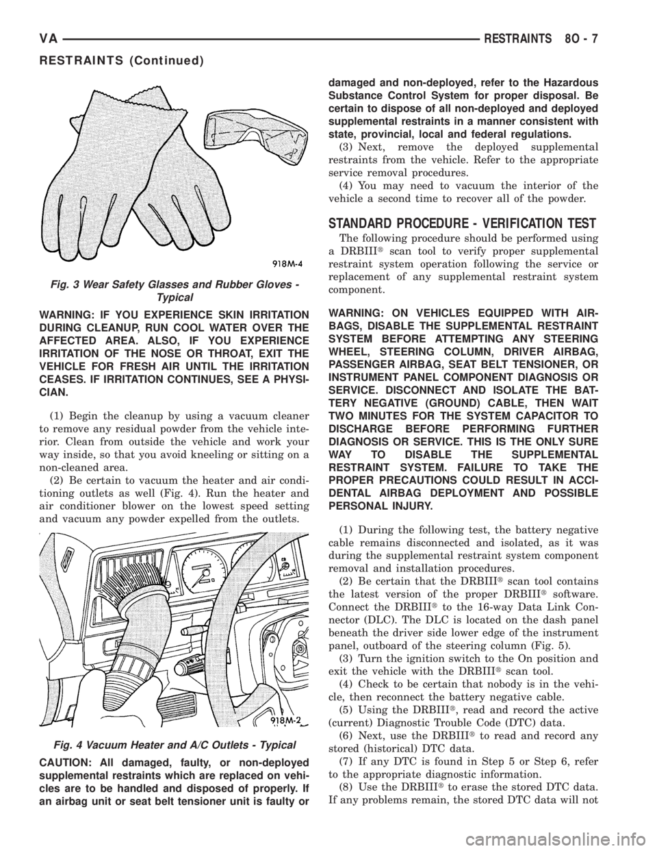
(2) Be certain to vacuum the heater and air condi-
tioning outlets as well (Fig. 4). Run the heater and
air conditioner blower on the lowest speed setting
and vacuum any powder expelled from the outlets.
CAUTION: All damaged, faulty, or non-deployed
supplemental restraints which are replaced on vehi-
cles are to be handled and disposed of properly. If
an airbag unit or seat belt tensioner unit is faulty ordamaged and non-deployed, refer to the Hazardous
Substance Control System for proper disposal. Be
certain to dispose of all non-deployed and deployed
supplemental restraints in a manner consistent with
state, provincial, local and federal regulations.
(3) Next, remove the deployed supplemental
restraints from the vehicle. Refer to the appropriate
service removal procedures.
(4) You may need to vacuum the interior of the
vehicle a second time to recover all of the powder.
STANDARD PROCEDURE - VERIFICATION TEST
The following procedure should be performed using
a DRBIIItscan tool to verify proper supplemental
restraint system operation following the service or
replacement of any supplemental restraint system
component.
WARNING: ON VEHICLES EQUIPPED WITH AIR-
BAGS, DISABLE THE SUPPLEMENTAL RESTRAINT
SYSTEM BEFORE ATTEMPTING ANY STEERING
WHEEL, STEERING COLUMN, DRIVER AIRBAG,
PASSENGER AIRBAG, SEAT BELT TENSIONER, OR
INSTRUMENT PANEL COMPONENT DIAGNOSIS OR
SERVICE. DISCONNECT AND ISOLATE THE BAT-
TERY NEGATIVE (GROUND) CABLE, THEN WAIT
TWO MINUTES FOR THE SYSTEM CAPACITOR TO
DISCHARGE BEFORE PERFORMING FURTHER
DIAGNOSIS OR SERVICE. THIS IS THE ONLY SURE
WAY TO DISABLE THE SUPPLEMENTAL
RESTRAINT SYSTEM. FAILURE TO TAKE THE
PROPER PRECAUTIONS COULD RESULT IN ACCI-
DENTAL AIRBAG DEPLOYMENT AND POSSIBLE
PERSONAL INJURY.
(1) During the following test, the battery negative
cable remains disconnected and isolated, as it was
during the supplemental restraint system component
removal and installation procedures.
(2) Be certain that the DRBIIItscan tool contains
the latest version of the proper DRBIIItsoftware.
Connect the DRBIIItto the 16-way Data Link Con-
nector (DLC). The DLC is located on the dash panel
beneath the driver side lower edge of the instrument
panel, outboard of the steering column (Fig. 5).
(3) Turn the ignition switch to the On position and
exit the vehicle with the DRBIIItscan tool.
(4) Check to be certain that nobody is in the vehi-
cle, then reconnect the battery negative cable.
(5) Using the DRBIIIt, read and record the active
(current) Diagnostic Trouble Code (DTC) data.
(6) Next, use the DRBIIItto read and record any
stored (historical) DTC data.
(7) If any DTC is found in Step 5 or Step 6, refer
to the appropriate diagnostic information.
(8) Use the DRBIIItto erase the stored DTC data.
If any problems remain, the stored DTC data will not
Fig. 3 Wear Safety Glasses and Rubber Gloves -
Typical
Fig. 4 Vacuum Heater and A/C Outlets - Typical
VARESTRAINTS 8O - 7
RESTRAINTS (Continued)
Page 248 of 1232
nosed and tested using conventional diagnostic tools
and procedures. However, conventional diagnostic
methods will not prove conclusive in the diagnosis of
the ACM or the supplemental restraint system. The
most reliable, efficient, and accurate means to diag-
nose the ACM or the supplemental restraint system
requires the use of a DRBIIItscan tool. Refer to the
appropriate diagnostic information.
REMOVAL
WARNING: ON VEHICLES EQUIPPED WITH AIR-
BAGS, DISABLE THE SUPPLEMENTAL RESTRAINT
SYSTEM BEFORE ATTEMPTING ANY STEERING
WHEEL, STEERING COLUMN, DRIVER AIRBAG,
PASSENGER AIRBAG, SEAT BELT TENSIONER, OR
INSTRUMENT PANEL COMPONENT DIAGNOSIS OR
SERVICE. DISCONNECT AND ISOLATE THE BAT-
TERY NEGATIVE (GROUND) CABLE, THEN WAIT
TWO MINUTES FOR THE SYSTEM CAPACITOR TO
DISCHARGE BEFORE PERFORMING FURTHER
DIAGNOSIS OR SERVICE. THIS IS THE ONLY SURE
WAY TO DISABLE THE SUPPLEMENTAL
RESTRAINT SYSTEM. FAILURE TO TAKE THE
PROPER PRECAUTIONS COULD RESULT IN ACCI-
DENTAL AIRBAG DEPLOYMENT AND POSSIBLE
PERSONAL INJURY.
WARNING: THE AIRBAG CONTROL MODULE CON-
TAINS THE IMPACT SENSOR, WHICH ENABLES
THE SYSTEM TO DEPLOY THE SUPPLEMENTAL
RESTRAINTS. NEVER STRIKE OR DROP THE AIR-
BAG CONTROL MODULE, AS IT CAN DAMAGE THE
IMPACT SENSOR OR AFFECT ITS CALIBRATION. IF
AN AIRBAG CONTROL MODULE IS ACCIDENTALLY
DROPPED DURING SERVICE, THE MODULE MUST
BE SCRAPPED AND REPLACED WITH A NEW UNIT.
FAILURE TO OBSERVE THIS WARNING COULD
RESULT IN ACCIDENTAL, INCOMPLETE, OR
IMPROPER SUPPLEMENTAL RESTRAINT DEPLOY-
MENT AND POSSIBLE OCCUPANT INJURIES.
(1) Disconnect and isolate the battery negative
cable. Wait two minutes for the system capacitor to
discharge before further service.
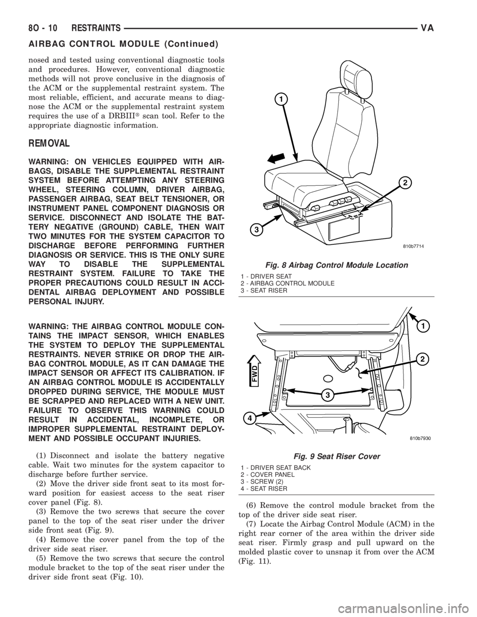
(2) Move the driver side front seat to its most for-
ward position for easiest access to the seat riser
cover panel (Fig. 8).
(3) Remove the two screws that secure the cover
panel to the top of the seat riser under the driver
side front seat (Fig. 9).
(4) Remove the cover panel from the top of the
driver side seat riser.
(5) Remove the two screws that secure the control
module bracket to the top of the seat riser under the
driver side front seat (Fig. 10).(6) Remove the control module bracket from the
top of the driver side seat riser.
(7) Locate the Airbag Control Module (ACM) in the
right rear corner of the area within the driver side
seat riser. Firmly grasp and pull upward on the
molded plastic cover to unsnap it from over the ACM
(Fig. 11).
Fig. 8 Airbag Control Module Location
1 - DRIVER SEAT
2 - AIRBAG CONTROL MODULE
3 - SEAT RISER
Fig. 9 Seat Riser Cover
1 - DRIVER SEAT BACK
2 - COVER PANEL
3 - SCREW (2)
4 - SEAT RISER
8O - 10 RESTRAINTSVA
AIRBAG CONTROL MODULE (Continued)
Page 249 of 1232
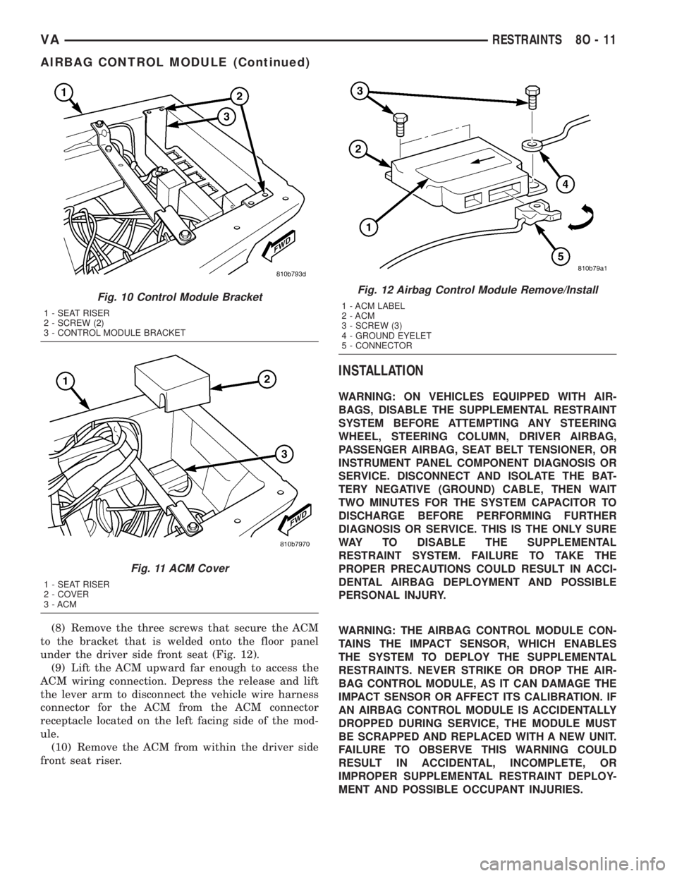
(8) Remove the three screws that secure the ACM
to the bracket that is welded onto the floor panel
under the driver side front seat (Fig. 12).
(9) Lift the ACM upward far enough to access the
ACM wiring connection. Depress the release and lift
the lever arm to disconnect the vehicle wire harness
connector for the ACM from the ACM connector
receptacle located on the left facing side of the mod-
ule.
(10) Remove the ACM from within the driver side
front seat riser.
INSTALLATION
WARNING: ON VEHICLES EQUIPPED WITH AIR-
BAGS, DISABLE THE SUPPLEMENTAL RESTRAINT
SYSTEM BEFORE ATTEMPTING ANY STEERING
WHEEL, STEERING COLUMN, DRIVER AIRBAG,
PASSENGER AIRBAG, SEAT BELT TENSIONER, OR
INSTRUMENT PANEL COMPONENT DIAGNOSIS OR
SERVICE. DISCONNECT AND ISOLATE THE BAT-
TERY NEGATIVE (GROUND) CABLE, THEN WAIT
TWO MINUTES FOR THE SYSTEM CAPACITOR TO
DISCHARGE BEFORE PERFORMING FURTHER
DIAGNOSIS OR SERVICE. THIS IS THE ONLY SURE
WAY TO DISABLE THE SUPPLEMENTAL
RESTRAINT SYSTEM. FAILURE TO TAKE THE
PROPER PRECAUTIONS COULD RESULT IN ACCI-
DENTAL AIRBAG DEPLOYMENT AND POSSIBLE
PERSONAL INJURY.
WARNING: THE AIRBAG CONTROL MODULE CON-
TAINS THE IMPACT SENSOR, WHICH ENABLES
THE SYSTEM TO DEPLOY THE SUPPLEMENTAL
RESTRAINTS. NEVER STRIKE OR DROP THE AIR-
BAG CONTROL MODULE, AS IT CAN DAMAGE THE
IMPACT SENSOR OR AFFECT ITS CALIBRATION. IF
AN AIRBAG CONTROL MODULE IS ACCIDENTALLY
DROPPED DURING SERVICE, THE MODULE MUST
BE SCRAPPED AND REPLACED WITH A NEW UNIT.
FAILURE TO OBSERVE THIS WARNING COULD
RESULT IN ACCIDENTAL, INCOMPLETE, OR
IMPROPER SUPPLEMENTAL RESTRAINT DEPLOY-
MENT AND POSSIBLE OCCUPANT INJURIES.
Fig. 10 Control Module Bracket
1 - SEAT RISER
2 - SCREW (2)
3 - CONTROL MODULE BRACKET
Fig. 11 ACM Cover
1 - SEAT RISER
2 - COVER
3 - ACM
Fig. 12 Airbag Control Module Remove/Install
1 - ACM LABEL
2 - ACM
3 - SCREW (3)
4 - GROUND EYELET
5 - CONNECTOR
VARESTRAINTS 8O - 11
AIRBAG CONTROL MODULE (Continued)
Page 250 of 1232
(1) Reconnect and latch the vehicle wire harness
connector for the ACM to the ACM connector recep-
tacle located on the left facing side of the module
(Fig. 12).
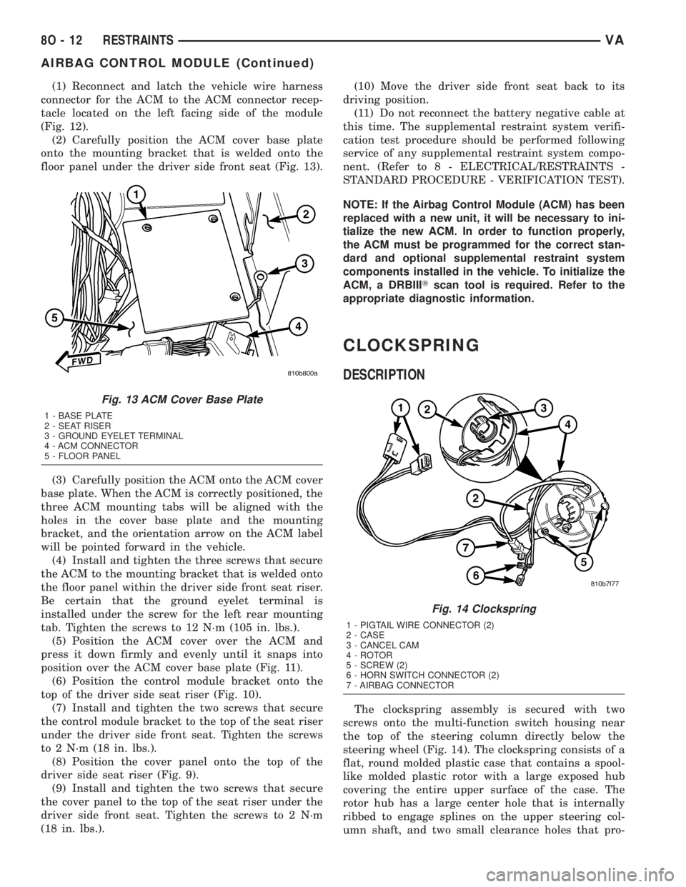
(2) Carefully position the ACM cover base plate
onto the mounting bracket that is welded onto the
floor panel under the driver side front seat (Fig. 13).
(3) Carefully position the ACM onto the ACM cover
base plate. When the ACM is correctly positioned, the
three ACM mounting tabs will be aligned with the
holes in the cover base plate and the mounting
bracket, and the orientation arrow on the ACM label
will be pointed forward in the vehicle.
(4) Install and tighten the three screws that secure
the ACM to the mounting bracket that is welded onto
the floor panel within the driver side front seat riser.
Be certain that the ground eyelet terminal is
installed under the screw for the left rear mounting
tab. Tighten the screws to 12 N´m (105 in. lbs.).
(5) Position the ACM cover over the ACM and
press it down firmly and evenly until it snaps into
position over the ACM cover base plate (Fig. 11).
(6) Position the control module bracket onto the
top of the driver side seat riser (Fig. 10).
(7) Install and tighten the two screws that secure
the control module bracket to the top of the seat riser
under the driver side front seat. Tighten the screws
to 2 N´m (18 in. lbs.).
(8) Position the cover panel onto the top of the
driver side seat riser (Fig. 9).
(9) Install and tighten the two screws that secure
the cover panel to the top of the seat riser under the
driver side front seat. Tighten the screws to 2 N´m
(18 in. lbs.).(10) Move the driver side front seat back to its
driving position.
(11) Do not reconnect the battery negative cable at
this time. The supplemental restraint system verifi-
cation test procedure should be performed following
service of any supplemental restraint system compo-
nent. (Refer to 8 - ELECTRICAL/RESTRAINTS -
STANDARD PROCEDURE - VERIFICATION TEST).
NOTE: If the Airbag Control Module (ACM) has been
replaced with a new unit, it will be necessary to ini-
tialize the new ACM. In order to function properly,
the ACM must be programmed for the correct stan-
dard and optional supplemental restraint system
components installed in the vehicle. To initialize the
ACM, a DRBIIITscan tool is required. Refer to the
appropriate diagnostic information.
CLOCKSPRING
DESCRIPTION
The clockspring assembly is secured with two
screws onto the multi-function switch housing near
the top of the steering column directly below the
steering wheel (Fig. 14). The clockspring consists of a
flat, round molded plastic case that contains a spool-
like molded plastic rotor with a large exposed hub
covering the entire upper surface of the case. The
rotor hub has a large center hole that is internally
ribbed to engage splines on the upper steering col-
umn shaft, and two small clearance holes that pro-
Fig. 13 ACM Cover Base Plate
1 - BASE PLATE
2 - SEAT RISER
3 - GROUND EYELET TERMINAL
4 - ACM CONNECTOR
5 - FLOOR PANEL
Fig. 14 Clockspring
1 - PIGTAIL WIRE CONNECTOR (2)
2 - CASE
3 - CANCEL CAM
4 - ROTOR
5 - SCREW (2)
6 - HORN SWITCH CONNECTOR (2)
7 - AIRBAG CONNECTOR
8O - 12 RESTRAINTSVA
AIRBAG CONTROL MODULE (Continued)
Page 251 of 1232
vide access to the case mounting screws. The lower
side of the rotor hub also serves as an integral
molded plastic turn signal cancel cam.
A single connector receptacle on the upper surface
of the rotor has pigtail wires that connect to the horn
switch and the driver airbag on the steering wheel,
while a single connector receptacle on the lower sur-
face of the case has pigtail wires that connect the
clockspring to the vehicle wire harness on the steer-
ing column. Within the plastic case and wound
around the rotor spool is a long ribbon-like tape that
consists of several thin copper wire leads sandwiched
between two thin plastic membranes. The outer end
of the tape terminates at the connector receptacle
that faces the steering column, while the inner end of
the tape terminates at the connector receptacle on
the hub of the clockspring rotor that faces the steer-
ing wheel.
Service replacement clocksprings are shipped pre-
centered and with the mounting screws backed out
from the case far enough to engage the access holes
in the upper surface of the rotor. The mounting
screws secure the centered clockspring rotor to the
clockspring case during shipment, but allow free
rotation of the rotor once the clockspring is properly
installed on the steering column. (Refer to 8 - ELEC-
TRICAL/RESTRAINTS/CLOCKSPRING - STAN-
DARD PROCEDURE - CLOCKSPRING
CENTERING).
The clockspring cannot be repaired. If the clock-
spring is faulty, damaged, or if the driver airbag has
been deployed, the clockspring must be replaced.
OPERATION
The clockspring is a mechanical electrical circuit
component that is used to provide continuous electri-
cal continuity between the fixed vehicle wire harness
and the electrical components mounted on or in the
rotating steering wheel. On this model the rotating
electrical components include the driver airbag and
the horn switch. The clockspring case is positioned
and secured to the multi-function switch housing
near the top of the steering column. The connector
receptacle on the underside of the fixed clockspring
case connects the clockspring to the vehicle electrical
system through two take outs with connectors from
the vehicle wire harness.
The clockspring rotor is movable and is keyed by
integral molded ribs on the inner circumference of
the rotor hub to the splines on the external circum-
ference of the upper steering column shaft. The two
integral lobes of the turn signal cancel cam formation
on the lower surface of the clockspring rotor hub con-
tact the turn signal cancel actuator of the multi-func-
tion switch to provide automatic turn signal
cancellation. The yellow sleeved pigtail wire on theupper surface of the clockspring rotor connects the
clockspring to the driver airbag, while two single pig-
tail wires connect to the feed and ground terminals of
the horn switch located within the hub cavity of the
steering wheel.
Like the clockspring in a timepiece, the clockspring
tape has travel limits and can be damaged by being
wound too tightly during full stop-to-stop steering
wheel rotation. To prevent this from occurring, the
clockspring is centered when it is installed on the
steering column. Centering the clockspring indexes
the clockspring tape to the movable steering compo-
nents so that the tape can operate within its
designed travel limits. However, if the clockspring is
removed from the steering column or if the steering
shaft is disconnected from the steering gear, the
clockspring spool can change position relative to the
movable steering components. The clockspring must
be re-centered following completion of this service or
the tape may be damaged.
Service replacement clocksprings are shipped pre-
centered and with the mounting screws backed out
from the case far enough to engage the access holes
in the upper surface of the rotor. The mounting
screws secure the centered clockspring rotor to the
clockspring case during shipment, but allow free
rotation of the rotor once the clockspring is properly
installed on the steering column. The clockspring
mounting screws should not be tightened into the
clockspring case until the clockspring has been
installed on the steering column. If the screws are
tightened into or removed from the case before the
clockspring is installed on a steering column, the
clockspring centering procedure must be performed.
(Refer to 8 - ELECTRICAL/RESTRAINTS/CLOCK-
SPRING - STANDARD PROCEDURE - CLOCK-
SPRING CENTERING).
STANDARD PROCEDURE - CLOCKSPRING
CENTERING
The clockspring is designed to wind and unwind
when the steering wheel is rotated, but is only
designed to rotate the same number of turns (about
six to seven complete rotations) as the steering wheel
can be turned from stop to stop. Centering the clock-
spring indexes the clockspring tape to other steering
components so that it can operate within its designed
travel limits. The rotor of a centered clockspring can
be rotated three to three and one-half turns in either
direction from the centered position, without damag-
ing the clockspring tape.
However, if the clockspring is removed for service
or if the steering column is disconnected from the
steering gear, the clockspring tape can change posi-
tion relative to the other steering components. The
clockspring must then be re-centered following com-
VARESTRAINTS 8O - 13
CLOCKSPRING (Continued)