2005 MERCEDES-BENZ SPRINTER clutch
[x] Cancel search: clutchPage 14 of 1232
Full synthetic oils, such as Mobilt1 0W-40, is
required if the ASSYST Oil Service Reminder is fol-
lowed. Use of a lower quality oil on this service
schedule may cause severe engine damage.
DESCRIPTION - AUTOMATIC TRANSMISSION
FLUID - NAG1
NOTE: Refer to Service Procedures in this group for
fluid level checking procedures.
Shellt3403 Automatic Transmission Fluid is the
recommended fluid for the NAG1 DaimlerChrysler
automatic transmission.
Dexron II fluid IS NOT recommended. Clutch
chatter can result from the use of improper
fluid.
MopartATF+4, Automatic Transmission Fluid, or
other fluids meeting MS-9602, may be used if Shellt
3403 Automatic Transmission Fluid is not available.
Shellt3403 Automatic Transmission Fluid when
new is red in color. The ATF is dyed red so it can be
identified from other fluids used in the vehicle such
as engine oil or antifreeze. The red color is not per-
manent and is not an indicator of fluid condition. As
the vehicle is driven, the ATF will begin to look
darker in color and may eventually become brown.
This is normal.
FLUID ADDITIVES
DaimlerChrysler strongly recommends against the
addition of any fluids to the transmission, other than
those automatic transmission fluids listed above.
Exceptions to this policy are the use of special dyes
to aid in detecting fluid leaks.
Various ªspecialº additives and supplements exist
that claim to improve shift feel and/or quality. These
additives and others also claim to improve converter
clutch operation and inhibit overheating, oxidation,
varnish, and sludge. These claims have not been sup-
ported to the satisfaction of DaimlerChrysler and
these additivesmust not be used.The use of trans-
mission ªsealersº should also be avoided, since they
may adversely affect the integrity of transmission
seals.
OPERATION - AUTOMATIC TRANSMISSION
FLUID
The automatic transmission fluid is selected based
upon several qualities. The fluid must provide a high
level of protection for the internal components by
providing a lubricating film between adjacent metal
components. The fluid must also be thermally stable
so that it can maintain a consistent viscosity through
a large temperature range. If the viscosity stays con-
stant through the temperature range of operation,transmission operation and shift feel will remain con-
sistent. Transmission fluid must also be a good con-
ductor of heat. The fluid must absorb heat from the
internal transmission components and transfer that
heat to the transmission case.
FLUID CAPACITIES
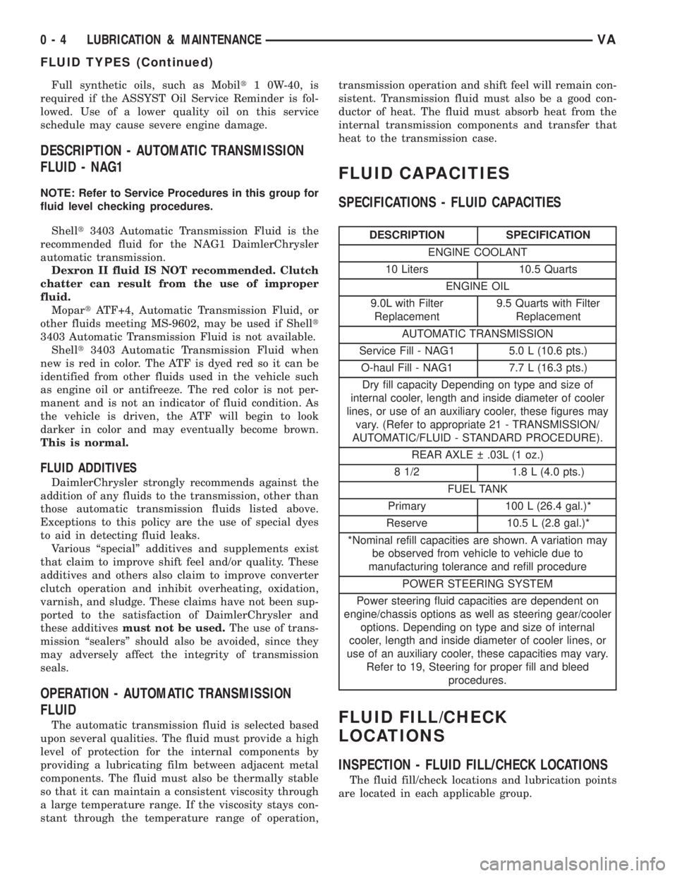
SPECIFICATIONS - FLUID CAPACITIES
DESCRIPTION SPECIFICATION
ENGINE COOLANT
10 Liters 10.5 Quarts
ENGINE OIL
9.0L with Filter
Replacement9.5 Quarts with Filter
Replacement
AUTOMATIC TRANSMISSION
Service Fill - NAG1 5.0 L (10.6 pts.)
O-haul Fill - NAG1 7.7 L (16.3 pts.)
Dry fill capacity Depending on type and size of
internal cooler, length and inside diameter of cooler
lines, or use of an auxiliary cooler, these figures may
vary. (Refer to appropriate 21 - TRANSMISSION/
AUTOMATIC/FLUID - STANDARD PROCEDURE).
REAR AXLE .03L (1 oz.)
8 1/2 1.8 L (4.0 pts.)
FUEL TANK
Primary 100 L (26.4 gal.)*
Reserve 10.5 L (2.8 gal.)*
*Nominal refill capacities are shown. A variation may
be observed from vehicle to vehicle due to
manufacturing tolerance and refill procedure
POWER STEERING SYSTEM
Power steering fluid capacities are dependent on
engine/chassis options as well as steering gear/cooler
options. Depending on type and size of internal
cooler, length and inside diameter of cooler lines, or
use of an auxiliary cooler, these capacities may vary.
Refer to 19, Steering for proper fill and bleed
procedures.
FLUID FILL/CHECK
LOCATIONS
INSPECTION - FLUID FILL/CHECK LOCATIONS
The fluid fill/check locations and lubrication points
are located in each applicable group.
0 - 4 LUBRICATION & MAINTENANCEVA
FLUID TYPES (Continued)
Page 18 of 1232
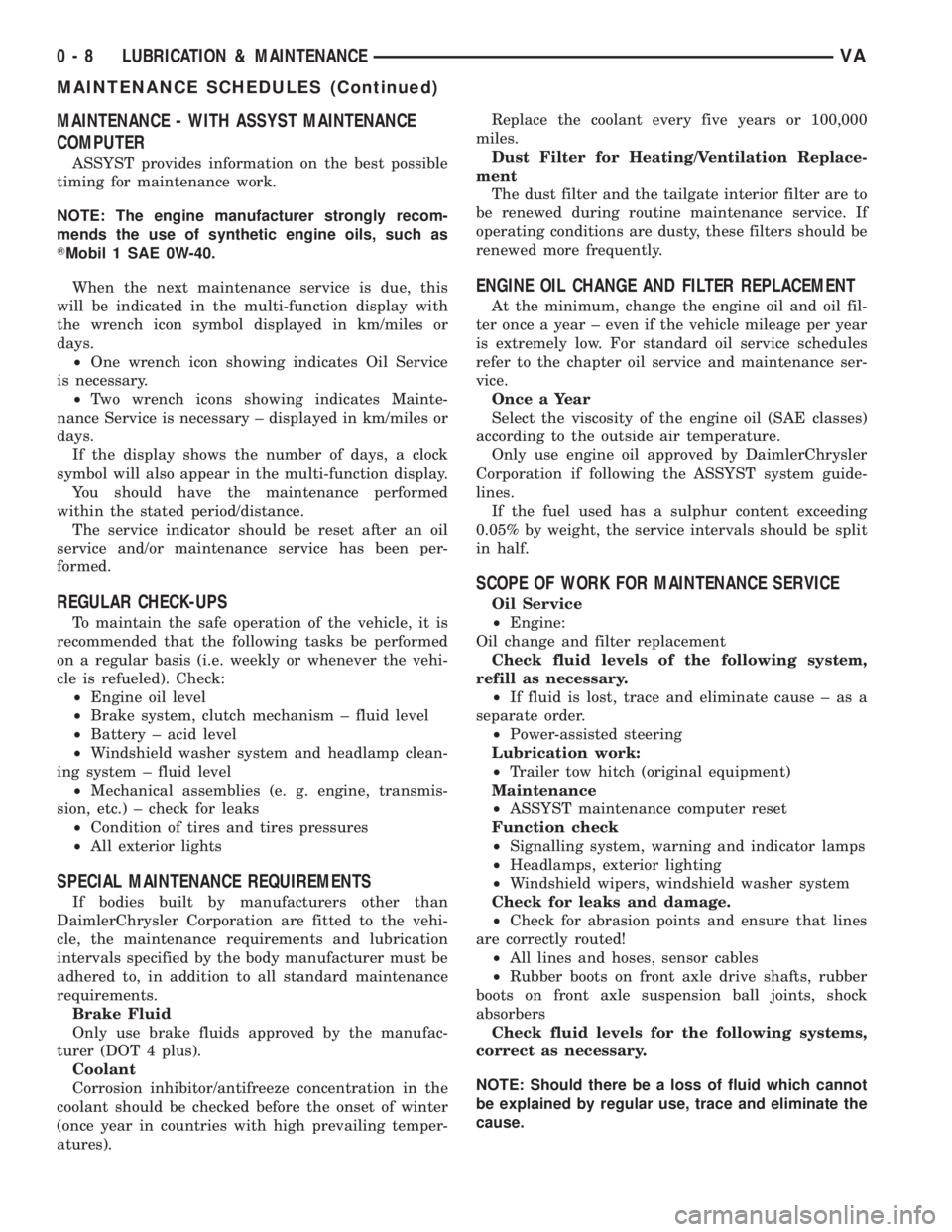
MAINTENANCE - WITH ASSYST MAINTENANCE
COMPUTER
ASSYST provides information on the best possible
timing for maintenance work.
NOTE: The engine manufacturer strongly recom-
mends the use of synthetic engine oils, such as
TMobil 1 SAE 0W-40.
When the next maintenance service is due, this
will be indicated in the multi-function display with
the wrench icon symbol displayed in km/miles or
days.
²One wrench icon showing indicates Oil Service
is necessary.
²Two wrench icons showing indicates Mainte-
nance Service is necessary ± displayed in km/miles or
days.
If the display shows the number of days, a clock
symbol will also appear in the multi-function display.
You should have the maintenance performed
within the stated period/distance.
The service indicator should be reset after an oil
service and/or maintenance service has been per-
formed.
REGULAR CHECK-UPS
To maintain the safe operation of the vehicle, it is
recommended that the following tasks be performed
on a regular basis (i.e. weekly or whenever the vehi-
cle is refueled). Check:
²Engine oil level
²Brake system, clutch mechanism ± fluid level
²Battery ± acid level
²Windshield washer system and headlamp clean-
ing system ± fluid level
²Mechanical assemblies (e. g. engine, transmis-
sion, etc.) ± check for leaks
²Condition of tires and tires pressures
²All exterior lights
SPECIAL MAINTENANCE REQUIREMENTS
If bodies built by manufacturers other than
DaimlerChrysler Corporation are fitted to the vehi-
cle, the maintenance requirements and lubrication
intervals specified by the body manufacturer must be
adhered to, in addition to all standard maintenance
requirements.
Brake Fluid
Only use brake fluids approved by the manufac-
turer (DOT 4 plus).
Coolant
Corrosion inhibitor/antifreeze concentration in the
coolant should be checked before the onset of winter
(once year in countries with high prevailing temper-
atures).Replace the coolant every five years or 100,000
miles.
Dust Filter for Heating/Ventilation Replace-
ment
The dust filter and the tailgate interior filter are to
be renewed during routine maintenance service. If
operating conditions are dusty, these filters should be
renewed more frequently.
ENGINE OIL CHANGE AND FILTER REPLACEMENT
At the minimum, change the engine oil and oil fil-
ter once a year ± even if the vehicle mileage per year
is extremely low. For standard oil service schedules
refer to the chapter oil service and maintenance ser-
vice.
Once a Year
Select the viscosity of the engine oil (SAE classes)
according to the outside air temperature.
Only use engine oil approved by DaimlerChrysler
Corporation if following the ASSYST system guide-
lines.
If the fuel used has a sulphur content exceeding
0.05% by weight, the service intervals should be split
in half.
SCOPE OF WORK FOR MAINTENANCE SERVICE
Oil Service
²Engine:
Oil change and filter replacement
Check fluid levels of the following system,
refill as necessary.
²If fluid is lost, trace and eliminate cause ± as a
separate order.
²Power-assisted steering
Lubrication work:
²Trailer tow hitch (original equipment)
Maintenance
²ASSYST maintenance computer reset
Function check
²Signalling system, warning and indicator lamps
²Headlamps, exterior lighting
²Windshield wipers, windshield washer system
Check for leaks and damage.
²Check for abrasion points and ensure that lines
are correctly routed!
²All lines and hoses, sensor cables
²Rubber boots on front axle drive shafts, rubber
boots on front axle suspension ball joints, shock
absorbers
Check fluid levels for the following systems,
correct as necessary.
NOTE: Should there be a loss of fluid which cannot
be explained by regular use, trace and eliminate the
cause.
0 - 8 LUBRICATION & MAINTENANCEVA
MAINTENANCE SCHEDULES (Continued)
Page 51 of 1232
heard during a coast, the front pinion bearing is the
source.
Differential bearings usually produce a low pitch
noise. Differential bearing noise is similar to pinion
bearing noise. The pitch of differential bearing noise
is also constant and varies only with vehicle speed.
Axle shaft bearingsproduce noise and vibration
when worn or damaged. The noise generally changes
when the bearings are loaded. Road test the vehicle.
Turn the vehicle sharply to the left and to the right.
This will load the bearings and change the noise
level. Where axle bearing damage is slight, the noise
is usually not noticeable at speeds above 30 mph.
LOW SPEED KNOCK
Low speed knock is generally caused by a worn
U-joint or by worn side-gear thrust washers. A worn
pinion shaft bore will also cause low speed knock.
VIBRATION
Vibration at the rear of the vehicle is usually
caused by a:
²Damaged drive shaft.
²Missing drive shaft balance weight(s).
²Worn or out-of-balance wheels.
²Loose wheel lug nuts.
²Worn U-joint(s).
²Loose/broken springs.
²Damaged axle shaft bearing(s).
²Loose pinion gear nut.
²Excessive pinion yoke run out.
²Bent axle shaft(s).
Check for loose or damaged front-end components
or engine/transmission mounts. These components
can contribute to what appears to be a rearend vibra-
tion. Do not overlook engine accessories, brackets
and drive belts.
NOTE: All driveline components should be exam-
ined before starting any repair.
DRIVELINE SNAP
A snap or clunk noise when the vehicle is shifted
into gear (or the clutch engaged), can be caused by:
²High engine idle speed.
²Transmission shift operation.
²Loose engine/transmission/transfer case mounts.
²Worn U-joints.
²Loose spring mounts.
²Loose pinion gear nut and yoke.
²Excessive ring gear backlash.
²Excessive side gear to case clearance.
The source of a snap or a clunk noise can be deter-
mined with the assistance of a helper. Raise the vehi-
cle on a hoist with the wheels free to rotate. Instruct
the helper to shift the transmission into gear. Listenfor the noise, a mechanics stethoscope is helpful in
isolating the source of a noise.
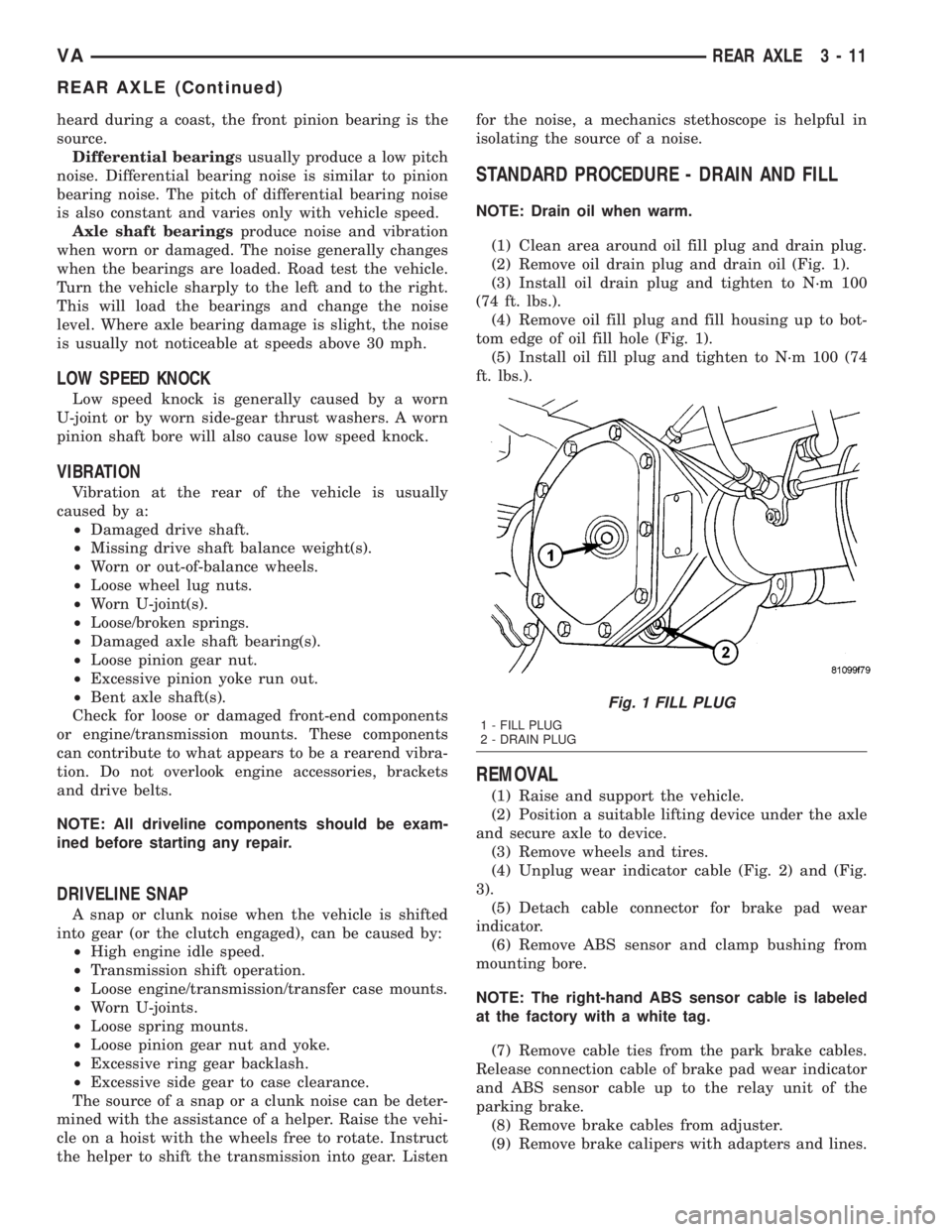
STANDARD PROCEDURE - DRAIN AND FILL
NOTE: Drain oil when warm.
(1) Clean area around oil fill plug and drain plug.
(2) Remove oil drain plug and drain oil (Fig. 1).
(3) Install oil drain plug and tighten to N´m 100
(74 ft. lbs.).
(4) Remove oil fill plug and fill housing up to bot-
tom edge of oil fill hole (Fig. 1).
(5) Install oil fill plug and tighten to N´m 100 (74
ft. lbs.).
REMOVAL
(1) Raise and support the vehicle.
(2) Position a suitable lifting device under the axle
and secure axle to device.
(3) Remove wheels and tires.
(4) Unplug wear indicator cable (Fig. 2) and (Fig.
3).
(5) Detach cable connector for brake pad wear
indicator.
(6) Remove ABS sensor and clamp bushing from
mounting bore.
NOTE: The right-hand ABS sensor cable is labeled
at the factory with a white tag.
(7) Remove cable ties from the park brake cables.
Release connection cable of brake pad wear indicator
and ABS sensor cable up to the relay unit of the
parking brake.
(8) Remove brake cables from adjuster.
(9) Remove brake calipers with adapters and lines.
Fig. 1 FILL PLUG
1 - FILL PLUG
2 - DRAIN PLUG
VAREAR AXLE 3 - 11
REAR AXLE (Continued)
Page 98 of 1232
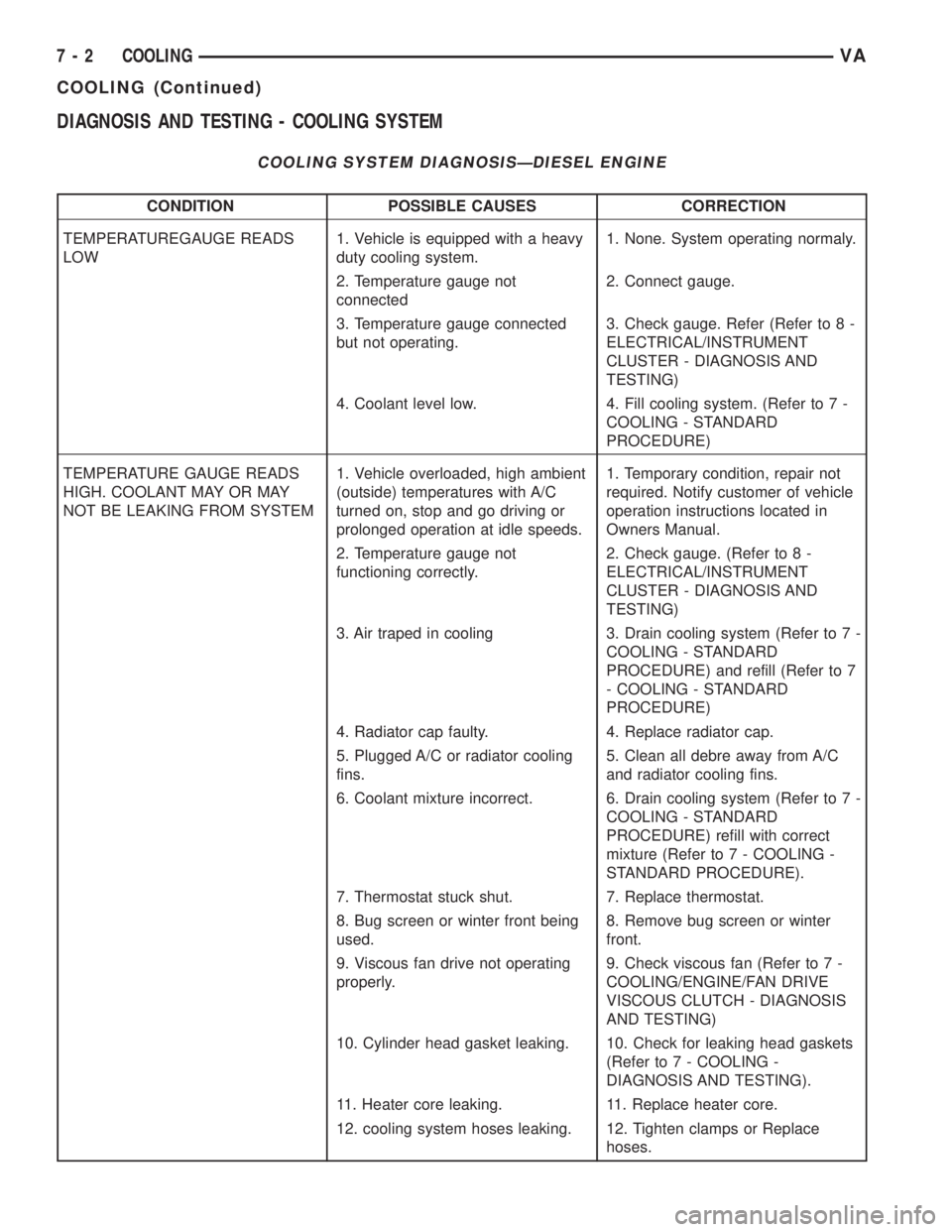
DIAGNOSIS AND TESTING - COOLING SYSTEM
COOLING SYSTEM DIAGNOSISÐDIESEL ENGINE
CONDITION POSSIBLE CAUSES CORRECTION
TEMPERATUREGAUGE READS
LOW1. Vehicle is equipped with a heavy
duty cooling system.1. None. System operating normaly.
2. Temperature gauge not
connected2. Connect gauge.
3. Temperature gauge connected
but not operating.3. Check gauge. Refer (Refer to 8 -
ELECTRICAL/INSTRUMENT
CLUSTER - DIAGNOSIS AND
TESTING)
4. Coolant level low. 4. Fill cooling system. (Refer to 7 -
COOLING - STANDARD
PROCEDURE)
TEMPERATURE GAUGE READS
HIGH. COOLANT MAY OR MAY
NOT BE LEAKING FROM SYSTEM1. Vehicle overloaded, high ambient
(outside) temperatures with A/C
turned on, stop and go driving or
prolonged operation at idle speeds.1. Temporary condition, repair not
required. Notify customer of vehicle
operation instructions located in
Owners Manual.
2. Temperature gauge not
functioning correctly.2. Check gauge. (Refer to 8 -
ELECTRICAL/INSTRUMENT
CLUSTER - DIAGNOSIS AND
TESTING)
3. Air traped in cooling 3. Drain cooling system (Refer to 7 -
COOLING - STANDARD
PROCEDURE) and refill (Refer to 7
- COOLING - STANDARD
PROCEDURE)
4. Radiator cap faulty. 4. Replace radiator cap.
5. Plugged A/C or radiator cooling
fins.5. Clean all debre away from A/C
and radiator cooling fins.
6. Coolant mixture incorrect. 6. Drain cooling system (Refer to 7 -
COOLING - STANDARD
PROCEDURE) refill with correct
mixture (Refer to 7 - COOLING -
STANDARD PROCEDURE).
7. Thermostat stuck shut. 7. Replace thermostat.
8. Bug screen or winter front being
used.8. Remove bug screen or winter
front.
9. Viscous fan drive not operating
properly.9. Check viscous fan (Refer to 7 -
COOLING/ENGINE/FAN DRIVE
VISCOUS CLUTCH - DIAGNOSIS
AND TESTING)
10. Cylinder head gasket leaking. 10. Check for leaking head gaskets
(Refer to 7 - COOLING -
DIAGNOSIS AND TESTING).
11. Heater core leaking. 11. Replace heater core.
12. cooling system hoses leaking. 12. Tighten clamps or Replace
hoses.
7 - 2 COOLINGVA
COOLING (Continued)
Page 100 of 1232
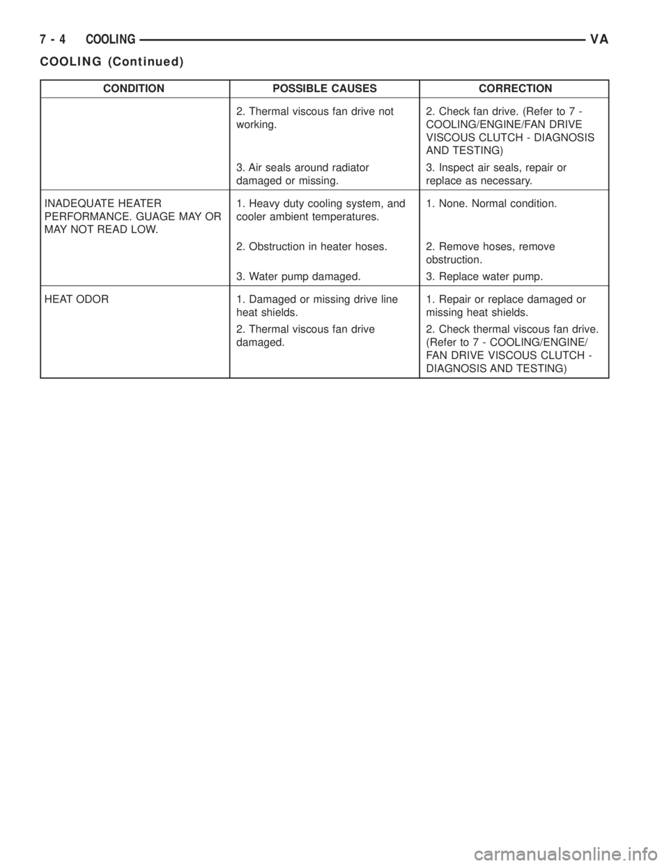
CONDITION POSSIBLE CAUSES CORRECTION
2. Thermal viscous fan drive not
working.2. Check fan drive. (Refer to 7 -
COOLING/ENGINE/FAN DRIVE
VISCOUS CLUTCH - DIAGNOSIS
AND TESTING)
3. Air seals around radiator
damaged or missing.3. Inspect air seals, repair or
replace as necessary.
INADEQUATE HEATER
PERFORMANCE. GUAGE MAY OR
MAY NOT READ LOW.1. Heavy duty cooling system, and
cooler ambient temperatures.1. None. Normal condition.
2. Obstruction in heater hoses. 2. Remove hoses, remove
obstruction.
3. Water pump damaged. 3. Replace water pump.
HEAT ODOR 1. Damaged or missing drive line
heat shields.1. Repair or replace damaged or
missing heat shields.
2. Thermal viscous fan drive
damaged.2. Check thermal viscous fan drive.
(Refer to 7 - COOLING/ENGINE/
FAN DRIVE VISCOUS CLUTCH -
DIAGNOSIS AND TESTING)
7 - 4 COOLINGVA
COOLING (Continued)
Page 105 of 1232
ENGINE
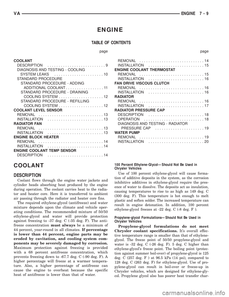
TABLE OF CONTENTS
page page
COOLANT
DESCRIPTION..........................9
DIAGNOSIS AND TESTING - COOLING
SYSTEM LEAKS......................10
STANDARD PROCEDURE
STANDARD PROCEDURE - ADDING
ADDITIONAL COOLANT.................11
STANDARD PROCEDURE - DRAINING
COOLING SYSTEM....................12
STANDARD PROCEDURE - REFILLING
COOLING SYSTEM....................12
COOLANT LEVEL SENSOR
REMOVAL.............................13
INSTALLATION.........................13
RADIATOR FAN
REMOVAL.............................13
INSTALLATION.........................13
ENGINE BLOCK HEATER
REMOVAL.............................14
INSTALLATION.........................14
ENGINE COOLANT TEMP SENSOR
DESCRIPTION.........................14REMOVAL.............................14
INSTALLATION.........................15
ENGINE COOLANT THERMOSTAT
REMOVAL.............................15
INSTALLATION.........................16
FAN DRIVE VISCOUS CLUTCH
REMOVAL.............................16
INSTALLATION.........................16
RADIATOR
REMOVAL.............................16
INSTALLATION.........................17
RADIATOR PRESSURE CAP
DESCRIPTION.........................18
OPERATION...........................18
DIAGNOSIS AND TESTING - RADIATOR
PRESSURE CAP......................19
WATER PUMP
REMOVAL.............................19
INSTALLATION.........................20
COOLANT
DESCRIPTION
Coolant flows through the engine water jackets and
cylinder heads absorbing heat produced by the engine
during operation. The coolant carries heat to the radia-
tor and heater core. Here it is transferred to ambient
air passing through the radiator and heater core fins.
The required ethylene-glycol (antifreeze) and water
mixture depends upon the climate and vehicle oper-
ating conditions. The recommended mixture of 50/50
ethylene-glycol and water will provide protection
against freezing to -37 deg. C (-35 deg. F). The anti-
freeze concentrationmust alwaysbe a minimum of
44 percent, year-round in all climates.If percentage
is lower than 44 percent, engine parts may be
eroded by cavitation, and cooling system com-
ponents may be severely damaged by corrosion.
Maximum protection against freezing is provided
with a 68 percent antifreeze concentration, which
prevents freezing down to -67.7 deg. C (-90 deg. F). A
higher percentage will freeze at a warmer tempera-
ture. Also, a higher percentage of antifreeze can
cause the engine to overheat because the specific
heat of antifreeze is lower than that of water.100 Percent Ethylene-GlycolÐShould Not Be Used in
Chrysler Vehicles
Use of 100 percent ethylene-glycol will cause forma-
tion of additive deposits in the system, as the corrosion
inhibitive additives in ethylene-glycol require the pres-
ence of water to dissolve. The deposits act as insulation,
causing temperatures to rise to as high as 149 deg. C
(300 deg. F). This temperature is hot enough to melt
plastic and soften solder. The increased temperature can
result in engine detonation. In addition, 100 percent
ethylene-glycol freezes at -22 deg. C (-8 deg. F ).
Propylene-glycol FormulationsÐShould Not Be Used in
Chrysler Vehicles
Propylene-glycol formulations do not meet
Chrysler coolant specifications.
It's overall effec-
tive temperature range is smaller than that of ethylene-
glycol. The freeze point of 50/50 propylene-glycol and
water is -32 deg. C (-26 deg. F). 5 deg. C higher than
ethylene-glycol's freeze point. The boiling point (protec-
tion against summer boil-over) of propylene-glycol is 125
deg. C (257 deg.F)at96.5 kPa (14 psi), compared to
128 deg. C (263 deg. F) for ethylene-glycol. Use of pro-
pylene-glycol can result in boil-over or freeze-up in
Chrysler vehicles, which are designed for ethylene-gly-
col. Propylene glycol also has poorer heat transfer char-
VAENGINE 7 - 9
Page 109 of 1232
COOLANT LEVEL SENSOR
REMOVAL
WARNING: RISK OF INJURY TO SKIN AND EYES
DUE TO SCALDING FROM HOT COOLANT. DO NOT
OPEN THE COOLING SYSTEM UNLESS THE TEM-
PERATURE IS BELOW 194ÉF (90ÉC). WEAR PRO-
TECTIVE CLOTHING AND EYE WEAR. RISK OF
POISONING IF COOLANT IS SWALLOWED. STORE
COOLANT IN PROPER AND APPROPRIATELY
MARKED CONTAINERS.
NOTE: Drain coolant from radiator drain plug only.
(1) Drain coolant until the coolant reservoir is
emptied.
(2) Disconnect the wiring harness electrical con-
nector.
(3) Turn the level sensor 90 degrees clockwises, lift
up and out of the container.
INSTALLATION
(1) Align coolant level sensor with coolant
reservior access whole, press down while turning
counterclockwise 90 degrees to seat sensor (Fig. 4).
(2) Connect coolant level sensor electrical connec-
tor (Fig. 4).
(3) Refill cooling system to proper level.
(4) Inspect for leaks.
RADIATOR FAN
REMOVAL
(1) Disconnect the negative battery cable.
(2) Remove the front end cross member.
(3) Push complete radiator assembly forward and
unclip the fan shroud at the radiator.
(4) Detach coolant line from lower radiator shroud.
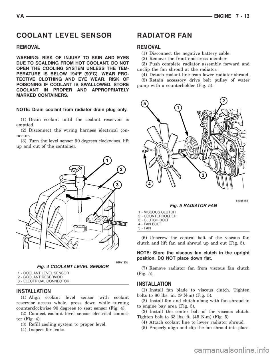
(5) Retain accessory drive belt pulley of water
pump with a counterholder (Fig. 5).
(6) Unscrew the central bolt of the viscous fan
clutch and lift fan and shroud up and out (Fig. 5).
NOTE: Store the viscous fan clutch in the upright
position. DO NOT place down flat.
(7) Remove radiator fan from viscous fan clutch
(Fig. 5).
INSTALLATION
(1) Install fan blade to viscous clutch. Tighten
bolts to 80 lbs. in. (9 N´m) (Fig. 5).
(2) Install fan and clutch along with fan shroud in
to engine bay area (Fig. 5).
(3) Install the center bolt of the viscous clutch.
Tighten bolt to 33 lbs. ft. (45 N´m) (Fig. 5)
(4) Attach coolant line to lower radiator shroud.
(5)
Properly align and clip the fan shroud into place.
Fig. 4 COOLANT LEVEL SENSOR
1 - COOLANT LEVEL SENSOR
2 - COOLANT RESERVIOR
3 - ELECTRICAL CONNECTOR
Fig. 5 RADIATOR FAN
1 - VISCOUS CLUTCH
2 - COUNTERHOLDER
3 - CLUTCH BOLT
4 - FAN BOLT
5-FAN
VAENGINE 7 - 13
Page 112 of 1232
INSTALLATION
(1) Clean all sealing surfaces.
(2) Position and install thermostat housing with
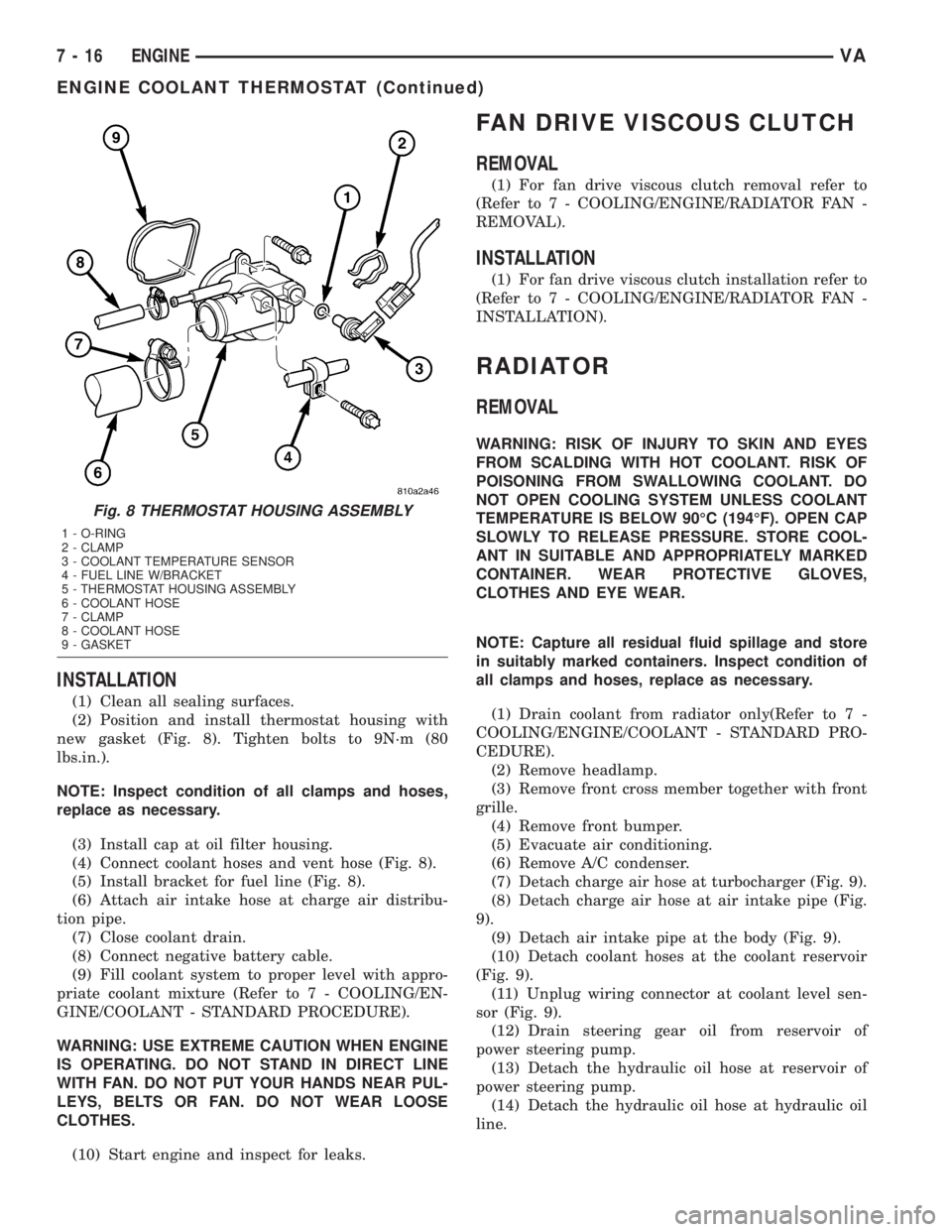
new gasket (Fig. 8). Tighten bolts to 9N´m (80
lbs.in.).
NOTE: Inspect condition of all clamps and hoses,
replace as necessary.
(3) Install cap at oil filter housing.
(4) Connect coolant hoses and vent hose (Fig. 8).
(5) Install bracket for fuel line (Fig. 8).
(6) Attach air intake hose at charge air distribu-
tion pipe.
(7) Close coolant drain.
(8) Connect negative battery cable.
(9) Fill coolant system to proper level with appro-
priate coolant mixture (Refer to 7 - COOLING/EN-
GINE/COOLANT - STANDARD PROCEDURE).
WARNING: USE EXTREME CAUTION WHEN ENGINE
IS OPERATING. DO NOT STAND IN DIRECT LINE
WITH FAN. DO NOT PUT YOUR HANDS NEAR PUL-
LEYS, BELTS OR FAN. DO NOT WEAR LOOSE
CLOTHES.
(10) Start engine and inspect for leaks.
FAN DRIVE VISCOUS CLUTCH
REMOVAL
(1) For fan drive viscous clutch removal refer to
(Refer to 7 - COOLING/ENGINE/RADIATOR FAN -
REMOVAL).
INSTALLATION
(1) For fan drive viscous clutch installation refer to
(Refer to 7 - COOLING/ENGINE/RADIATOR FAN -
INSTALLATION).
RADIATOR
REMOVAL
WARNING: RISK OF INJURY TO SKIN AND EYES
FROM SCALDING WITH HOT COOLANT. RISK OF
POISONING FROM SWALLOWING COOLANT. DO
NOT OPEN COOLING SYSTEM UNLESS COOLANT
TEMPERATURE IS BELOW 90ÉC (194ÉF). OPEN CAP
SLOWLY TO RELEASE PRESSURE. STORE COOL-
ANT IN SUITABLE AND APPROPRIATELY MARKED
CONTAINER. WEAR PROTECTIVE GLOVES,
CLOTHES AND EYE WEAR.
NOTE: Capture all residual fluid spillage and store
in suitably marked containers. Inspect condition of
all clamps and hoses, replace as necessary.
(1) Drain coolant from radiator only(Refer to 7 -
COOLING/ENGINE/COOLANT - STANDARD PRO-
CEDURE).
(2) Remove headlamp.
(3) Remove front cross member together with front
grille.
(4) Remove front bumper.
(5) Evacuate air conditioning.
(6) Remove A/C condenser.
(7) Detach charge air hose at turbocharger (Fig. 9).
(8) Detach charge air hose at air intake pipe (Fig.
9).
(9) Detach air intake pipe at the body (Fig. 9).
(10) Detach coolant hoses at the coolant reservoir
(Fig. 9).
(11) Unplug wiring connector at coolant level sen-
sor (Fig. 9).
(12) Drain steering gear oil from reservoir of
power steering pump.
(13) Detach the hydraulic oil hose at reservoir of
power steering pump.
(14) Detach the hydraulic oil hose at hydraulic oil
line.
Fig. 8 THERMOSTAT HOUSING ASSEMBLY
1 - O-RING
2 - CLAMP
3 - COOLANT TEMPERATURE SENSOR
4 - FUEL LINE W/BRACKET
5 - THERMOSTAT HOUSING ASSEMBLY
6 - COOLANT HOSE
7 - CLAMP
8 - COOLANT HOSE
9 - GASKET
7 - 16 ENGINEVA
ENGINE COOLANT THERMOSTAT (Continued)