2005 MERCEDES-BENZ SPRINTER coolant reservoir
[x] Cancel search: coolant reservoirPage 99 of 1232
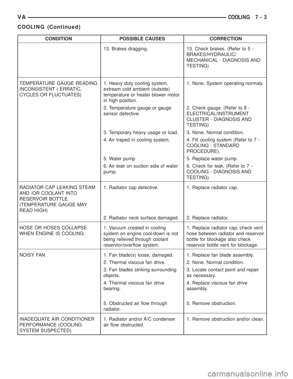
CONDITION POSSIBLE CAUSES CORRECTION
13. Brakes dragging. 13. Check brakes. (Refer to 5 -
BRAKES/HYDRAULIC/
MECHANICAL - DIAGNOSIS AND
TESTING)
TEMPERATURE GAUGE READING
INCONSISTENT ( ERRATIC,
CYCLES OR FLUCTUATES)1. Heavy duty cooling system,
extream cold ambient (outside)
temperature or heater blower motor
in high position.1. None. System operating normaly.
2. Temperature gauge or gauge
sensor defective.2. Check gauge. (Refer to 8 -
ELECTRICAL/INSTRUMENT
CLUSTER - DIAGNOSIS AND
TESTING)
3. Temporary heavy usage or load. 3. None. Normal condition.
4. Air traped in cooling system. 4. Fill cooling system (Refer to 7 -
COOLING - STANDARD
PROCEDURE).
5. Water pump 5. Replace water pump.
6. Air leak on suction side of water
pump.6. Check for leak. (Refer to 7 -
COOLING - DIAGNOSIS AND
TESTING)
RADIATOR CAP LEAKING STEAM
AND /OR COOLANT INTO
RESERVOIR BOTTLE.
(TEMPERATURE GAUGE MAY
READ HIGH)1. Radiator cap defective. 1. Replace radiator cap.
2. Radiator neck surface damaged. 2. Replace radiator.
HOSE OR HOSES COLLAPSE
WHEN ENGINE IS COOLING.1. Vacuum created in cooling
system on engine cool-down is not
being relieved through coolant
reservior/overflow system.1. Replace radiator cap, check vent
hose between radiator and reservoir
bottle for blockage also check
reservoir bottle vent for blockage.
NOISY FAN 1. Fan blade(s) loose, damaged. 1. Replace fan blade assembly.
2. Thermal viscous fan drive. 2. None. Normal condition.
3. Fan blades striking surrounding
objects.3. Locate contact point and repair
as necessary.
4. Thermal viscous fan drive
bearing.4. Replace viscous fan drive
assembly.
5. Obstructed air flow through
radiator.5. Remove obstruction.
INADEQUATE AIR CONDITIONER
PERFORMANCE (COOLING
SYSTEM SUSPECTED)1. Radiator and/or A/C condenser
air flow obstructed.1. Remove obstruction and/or clean.
VACOOLING 7 - 3
COOLING (Continued)
Page 106 of 1232
acteristics than ethylene glycol. This can increase
cylinder head temperatures under certain conditions.
Propylene-glycol/Ethylene-glycol MixturesÐShould Not Be
Used in Chrysler Vehicles
Propylene-glycol/ethylene-glycol Mixtures can
cause the destabilization of various corrosion inhibi-
tors, causing damage to the various cooling system
components. Also, once ethylene-glycol and propy-
lene-glycol based coolants are mixed in the vehicle,
conventional methods of determining freeze point will
not be accurate. Both the refractive index and spe-
cific gravity differ between ethylene glycol and propy-
lene glycol.
CAUTION: Richer antifreeze mixtures cannot be
measured with normal field equipment and can
cause problems associated with 100 percent ethyl-
ene-glycol.
DIAGNOSIS AND TESTING - COOLING SYSTEM
LEAKS
ULTRAVIOLET LIGHT METHOD
A leak detection additive is available through the
parts department that can be added to cooling sys-
tem. The additive is highly visible under ultraviolet
light (black light). Pour one ounce of additive into
cooling system. Place heater control unit in HEAT
position. Start and operate engine until radiator
upper hose is warm to touch. Aim the commercially
available black light tool at components to be
checked. If leaks are present, black light will cause
additive to glow a bright green color.
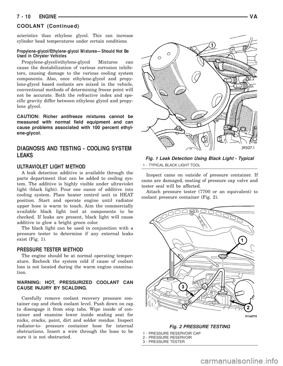
The black light can be used in conjunction with a
pressure tester to determine if any external leaks
exist (Fig. 1).
PRESSURE TESTER METHOD
The engine should be at normal operating temper-
ature. Recheck the system cold if cause of coolant
loss is not located during the warm engine examina-
tion.
WARNING: HOT, PRESSURIZED COOLANT CAN
CAUSE INJURY BY SCALDING.
Carefully remove coolant recovery pressure con-
tainer cap and check coolant level. Push down on cap
to disengage it from stop tabs. Wipe inside of con-
tainer and examine lower inside sealing seat for
nicks, cracks, paint, dirt and solder residue. Inspect
radiator-to- pressure container hose for internal
obstructions. Insert a wire through the hose to be
sure it is not obstructed.Inspect cams on outside of pressure container. If
cams are damaged, seating of pressure cap valve and
tester seal will be affected.
Attach pressure tester (7700 or an equivalent) to
coolant pressure container (Fig. 2).
Fig. 1 Leak Detection Using Black Light - Typical
1 - TYPICAL BLACK LIGHT TOOL
Fig. 2 PRESSURE TESTING
1 - PRESSURE RESERVOIR CAP
2 - PRESSURE RESERVOIR
3 - PRESSURE TESTER
7 - 10 ENGINEVA
COOLANT (Continued)
Page 109 of 1232
COOLANT LEVEL SENSOR
REMOVAL
WARNING: RISK OF INJURY TO SKIN AND EYES
DUE TO SCALDING FROM HOT COOLANT. DO NOT
OPEN THE COOLING SYSTEM UNLESS THE TEM-
PERATURE IS BELOW 194ÉF (90ÉC). WEAR PRO-
TECTIVE CLOTHING AND EYE WEAR. RISK OF
POISONING IF COOLANT IS SWALLOWED. STORE
COOLANT IN PROPER AND APPROPRIATELY
MARKED CONTAINERS.
NOTE: Drain coolant from radiator drain plug only.
(1) Drain coolant until the coolant reservoir is
emptied.
(2) Disconnect the wiring harness electrical con-
nector.
(3) Turn the level sensor 90 degrees clockwises, lift
up and out of the container.
INSTALLATION
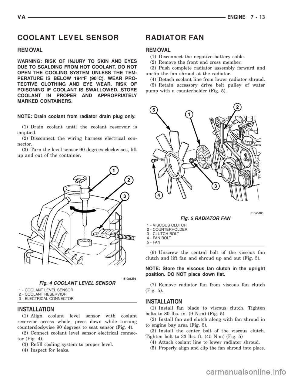
(1) Align coolant level sensor with coolant
reservior access whole, press down while turning
counterclockwise 90 degrees to seat sensor (Fig. 4).
(2) Connect coolant level sensor electrical connec-
tor (Fig. 4).
(3) Refill cooling system to proper level.
(4) Inspect for leaks.
RADIATOR FAN
REMOVAL
(1) Disconnect the negative battery cable.
(2) Remove the front end cross member.
(3) Push complete radiator assembly forward and
unclip the fan shroud at the radiator.
(4) Detach coolant line from lower radiator shroud.
(5) Retain accessory drive belt pulley of water
pump with a counterholder (Fig. 5).
(6) Unscrew the central bolt of the viscous fan
clutch and lift fan and shroud up and out (Fig. 5).
NOTE: Store the viscous fan clutch in the upright
position. DO NOT place down flat.
(7) Remove radiator fan from viscous fan clutch
(Fig. 5).
INSTALLATION
(1) Install fan blade to viscous clutch. Tighten
bolts to 80 lbs. in. (9 N´m) (Fig. 5).
(2) Install fan and clutch along with fan shroud in
to engine bay area (Fig. 5).
(3) Install the center bolt of the viscous clutch.
Tighten bolt to 33 lbs. ft. (45 N´m) (Fig. 5)
(4) Attach coolant line to lower radiator shroud.
(5)
Properly align and clip the fan shroud into place.
Fig. 4 COOLANT LEVEL SENSOR
1 - COOLANT LEVEL SENSOR
2 - COOLANT RESERVIOR
3 - ELECTRICAL CONNECTOR
Fig. 5 RADIATOR FAN
1 - VISCOUS CLUTCH
2 - COUNTERHOLDER
3 - CLUTCH BOLT
4 - FAN BOLT
5-FAN
VAENGINE 7 - 13
Page 112 of 1232
INSTALLATION
(1) Clean all sealing surfaces.
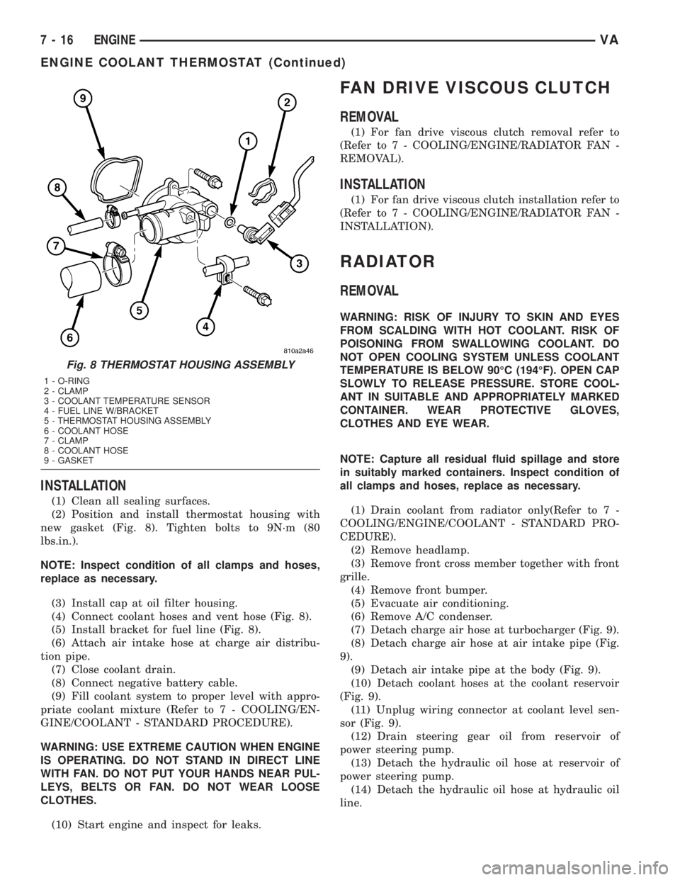
(2) Position and install thermostat housing with
new gasket (Fig. 8). Tighten bolts to 9N´m (80
lbs.in.).
NOTE: Inspect condition of all clamps and hoses,
replace as necessary.
(3) Install cap at oil filter housing.
(4) Connect coolant hoses and vent hose (Fig. 8).
(5) Install bracket for fuel line (Fig. 8).
(6) Attach air intake hose at charge air distribu-
tion pipe.
(7) Close coolant drain.
(8) Connect negative battery cable.
(9) Fill coolant system to proper level with appro-
priate coolant mixture (Refer to 7 - COOLING/EN-
GINE/COOLANT - STANDARD PROCEDURE).
WARNING: USE EXTREME CAUTION WHEN ENGINE
IS OPERATING. DO NOT STAND IN DIRECT LINE
WITH FAN. DO NOT PUT YOUR HANDS NEAR PUL-
LEYS, BELTS OR FAN. DO NOT WEAR LOOSE
CLOTHES.
(10) Start engine and inspect for leaks.
FAN DRIVE VISCOUS CLUTCH
REMOVAL
(1) For fan drive viscous clutch removal refer to
(Refer to 7 - COOLING/ENGINE/RADIATOR FAN -
REMOVAL).
INSTALLATION
(1) For fan drive viscous clutch installation refer to
(Refer to 7 - COOLING/ENGINE/RADIATOR FAN -
INSTALLATION).
RADIATOR
REMOVAL
WARNING: RISK OF INJURY TO SKIN AND EYES
FROM SCALDING WITH HOT COOLANT. RISK OF
POISONING FROM SWALLOWING COOLANT. DO
NOT OPEN COOLING SYSTEM UNLESS COOLANT
TEMPERATURE IS BELOW 90ÉC (194ÉF). OPEN CAP
SLOWLY TO RELEASE PRESSURE. STORE COOL-
ANT IN SUITABLE AND APPROPRIATELY MARKED
CONTAINER. WEAR PROTECTIVE GLOVES,
CLOTHES AND EYE WEAR.
NOTE: Capture all residual fluid spillage and store
in suitably marked containers. Inspect condition of
all clamps and hoses, replace as necessary.
(1) Drain coolant from radiator only(Refer to 7 -
COOLING/ENGINE/COOLANT - STANDARD PRO-
CEDURE).
(2) Remove headlamp.
(3) Remove front cross member together with front
grille.
(4) Remove front bumper.
(5) Evacuate air conditioning.
(6) Remove A/C condenser.
(7) Detach charge air hose at turbocharger (Fig. 9).
(8) Detach charge air hose at air intake pipe (Fig.
9).
(9) Detach air intake pipe at the body (Fig. 9).
(10) Detach coolant hoses at the coolant reservoir
(Fig. 9).
(11) Unplug wiring connector at coolant level sen-
sor (Fig. 9).
(12) Drain steering gear oil from reservoir of
power steering pump.
(13) Detach the hydraulic oil hose at reservoir of
power steering pump.
(14) Detach the hydraulic oil hose at hydraulic oil
line.
Fig. 8 THERMOSTAT HOUSING ASSEMBLY
1 - O-RING
2 - CLAMP
3 - COOLANT TEMPERATURE SENSOR
4 - FUEL LINE W/BRACKET
5 - THERMOSTAT HOUSING ASSEMBLY
6 - COOLANT HOSE
7 - CLAMP
8 - COOLANT HOSE
9 - GASKET
7 - 16 ENGINEVA
ENGINE COOLANT THERMOSTAT (Continued)
Page 113 of 1232
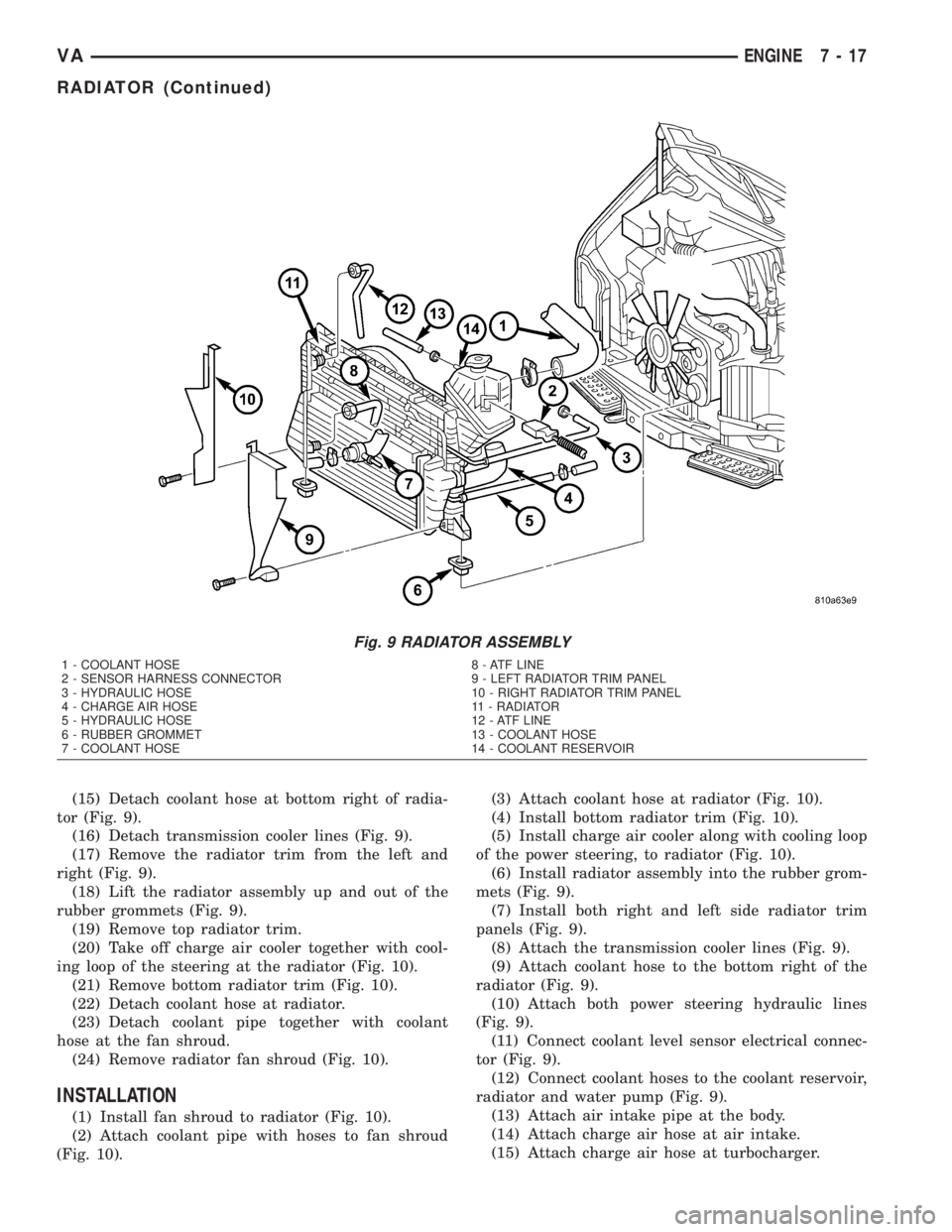
(15) Detach coolant hose at bottom right of radia-
tor (Fig. 9).
(16) Detach transmission cooler lines (Fig. 9).
(17) Remove the radiator trim from the left and
right (Fig. 9).
(18) Lift the radiator assembly up and out of the
rubber grommets (Fig. 9).
(19) Remove top radiator trim.
(20) Take off charge air cooler together with cool-
ing loop of the steering at the radiator (Fig. 10).
(21) Remove bottom radiator trim (Fig. 10).
(22) Detach coolant hose at radiator.
(23) Detach coolant pipe together with coolant
hose at the fan shroud.
(24) Remove radiator fan shroud (Fig. 10).
INSTALLATION
(1) Install fan shroud to radiator (Fig. 10).
(2) Attach coolant pipe with hoses to fan shroud
(Fig. 10).(3) Attach coolant hose at radiator (Fig. 10).
(4) Install bottom radiator trim (Fig. 10).
(5) Install charge air cooler along with cooling loop
of the power steering, to radiator (Fig. 10).
(6) Install radiator assembly into the rubber grom-
mets (Fig. 9).
(7) Install both right and left side radiator trim
panels (Fig. 9).
(8) Attach the transmission cooler lines (Fig. 9).
(9) Attach coolant hose to the bottom right of the
radiator (Fig. 9).
(10) Attach both power steering hydraulic lines
(Fig. 9).
(11) Connect coolant level sensor electrical connec-
tor (Fig. 9).
(12) Connect coolant hoses to the coolant reservoir,
radiator and water pump (Fig. 9).
(13) Attach air intake pipe at the body.
(14) Attach charge air hose at air intake.
(15) Attach charge air hose at turbocharger.
Fig. 9 RADIATOR ASSEMBLY
1 - COOLANT HOSE 8 - ATF LINE
2 - SENSOR HARNESS CONNECTOR 9 - LEFT RADIATOR TRIM PANEL
3 - HYDRAULIC HOSE 10 - RIGHT RADIATOR TRIM PANEL
4 - CHARGE AIR HOSE 11 - RADIATOR
5 - HYDRAULIC HOSE 12 - ATF LINE
6 - RUBBER GROMMET 13 - COOLANT HOSE
7 - COOLANT HOSE 14 - COOLANT RESERVOIR
VAENGINE 7 - 17
RADIATOR (Continued)
Page 197 of 1232
the wait-to-start indicator will be illuminated. The
indicator remains illuminated until the cluster
receives a wait-to-start lamp-off message indicating
that the pre-heat mode of the glow plugs has been
completed, until the ECM detects that the engine is
running, or until the ignition switch is turned to the
Off position, whichever occurs first.
The ECM continually monitors the engine coolant
temperature sensor to determine when the glow
plugs need to be energized in their pre-heat operat-
ing mode. The ECM then sends the proper wait-to-
start lamp-on and lamp-off messages to the
instrument cluster. If the instrument cluster turns on
the indicator after the engine is started, it may indi-
cate that a malfunction has occurred and that the
engine glow control system requires service. The
ECM will store a Diagnostic Trouble Code (DTC) for
any malfunction it detects. For proper diagnosis of
the engine coolant temperature sensor, the engine
glow control system and circuits, the ECM, the CAN
data bus, or the electronic message inputs to the
instrument cluster that control the wait-to-start indi-
cator, a DRBIIItscan tool is required. Refer to the
appropriate diagnostic information.
WASHER FLUID INDICATOR
DESCRIPTION
A washer fluid indicator is standard equipment on
all instrument clusters. However, this indicator is
only functional on vehicles equipped with an optional
washer fluid level switch integral to the washer
pump/motor unit on the washer reservoir. The
washer fluid indicator is located near the lower edge
of the instrument cluster, to the right of the multi-
function indicator display. The washer fluid indicator
consists of the International Control and Display
Symbol icon for ªWindshield Washer Fluidº imprinted
within a rectangular cutout in the opaque layer of
the instrument cluster overlay. The dark outer layer
of the overlay prevents the indicator from being
clearly visible when it is not illuminated. An amber
Light Emitting Diode (LED) behind the cutout in the
opaque layer of the overlay causes the icon to appear
silhouetted against an amber field through the trans-
lucent outer layer of the overlay when the indicator
is illuminated from behind by the LED, which is sol-
dered onto the instrument cluster electronic circuit
board. The washer fluid indicator is serviced as a
unit with the instrument cluster.
OPERATION
The washer fluid indicator gives an indication to
the vehicle operator that the fluid level in the washer
reservoir is low. This indicator is controlled by theinstrument cluster circuit board based upon cluster
programming and a hard wired input from the
optional washer fluid level switch that is integral to
the washer pump/motor unit. The washer fluid indi-
cator is completely controlled by the instrument clus-
ter logic circuit, and that logic will only allow this
indicator to operate when the instrument cluster
detects that the ignition switch is in the On position.
Therefore, the indicator will always be off when the
ignition switch is in any position except On. The indi-
cator only illuminates when it is switched to ground
by the instrument cluster circuitry. The instrument
cluster will turn on the washer fluid indicator for the
following reasons:
²Bulb Test- Each time the ignition switch is
turned to the On position the brake wear indicator is
illuminated by the instrument cluster for about two
seconds as a bulb test.
²Washer Fluid Level Switch Input- Each time
the cluster detects ground on the washer fluid switch
sense circuit (washer fluid level switch closed =
washer fluid level low) while the ignition switch is in
the On position, the washer fluid indicator is illumi-
nated. The indicator remains illuminated until the
washer fluid level switch input to the cluster is an
open circuit (washer fluid level switch open = washer
fluid level acceptable), or until the ignition switch is
turned to the Off position, whichever occurs first.
The instrument cluster continually monitors the
washer fluid level switch to determine the level of
the washer fluid. The instrument cluster logic applies
a delay strategy to this input to reduce the negative
effect that fluid sloshing within the reservoir can
have on reliable indicator operation. The washer
fluid level switch and circuit can be diagnosed using
conventional diagnostic tools and methods. For
proper diagnosis of the instrument cluster circuitry
that controls the washer fluid indicator, a DRBIIIt
scan tool is required. Refer to the appropriate diag-
nostic information.
WATER-IN-FUEL INDICATOR
DESCRIPTION
A water-in-fuel indicator is standard equipment in
all instrument clusters. The water-in-fuel indicator is
located near the lower edge of the instrument cluster,
to the left of the multi-function indicator display. The
water-in-fuel indicator consists of the International
Control and Display Symbol icon for ªWater In Fuelº
imprinted within a rectangular cutout in the opaque
layer of the instrument cluster overlay. The dark
outer layer of the overlay prevents the indicator from
being clearly visible when it is not illuminated. An
amber Light Emitting Diode (LED) behind the cutout
VAINSTRUMENT CLUSTER 8J - 27
WAIT-TO-START INDICATOR (Continued)
Page 742 of 1232
CYLINDER LEAK DOWN VALUES
CYLINDER LEAK DOWN
PERMISSIBLE TOTAL
LOSS 25%
CYLINDER LEAK DOWN
PERMISSIBLE LOSS AT
VALVES AND CYLINDER
HEAD 10%
CYLINDER LEAK DOWN
PERMISSIBLE LOSS AT
PISTON AND RINGS 20%
STANDARD PROCEDURE - DETERMINING
CYLINDER PRESSURE LOSS
If an increased pressure loss was found with the
cylinder leak test, inspect the engine by listening at
the cylinder head gasket, air intake area, exhaust, oil
fill opening and where injectors and glow plugs enter
the cylinder head. Also check the engine coolant in
the radiator or expansion reservoir for the formation
of bubbles.
Possible causes for the pressure loss are:
POSSIBLE CAUSE FOR PRESSURE LOSS
CONDITION POSSIBLE
CAUSESCORRECTION
AIR LOSS
THROUGH
GLOW PLUG,
INJECTOR,
ADJACENT
CYLINDERS,
OR AIR
BUBBLES IN
COOLANT1. Sealing
SurfacesRepair Sealing
Surfaces
2. Gaskets 2. Replace
Component or
Gasket
3. Cylinder
Head Gasket3. Replace
Cylinder Head
Gasket
AIR LOSS
THROUGH AIR
INTAKE AREA1. Sealing
Surfaces1. Remove
Cylinder Head
for Further
Inspection
2. Intake Valves
and Seats2. Replace
Valves, Guides
or Seats
CONDITION POSSIBLE
CAUSESCORRECTION
AIR LOSS
THROUGH
EXHAUSTSealing
SurfacesRemove
Cylinder Head
for Further
Inspection
2. Exhaust
Valves and
Seats2. Replace
Valves, Guides
or Seats
AIR LOSS
THROUGH OIL
FILL OPENING1. Sealing
SurfacesRemove Engine
for Further
Inspection
2. Pistons,
Piston Rings2. Replace
Pistons or
Piston Rings
It is possible to pin point the pressure loss of the
relevant cylinder by spraying with clean engine oil.
Engine oil seals off the gap between the piston and
cylinder wall briefly. If a reduced pressure loss now
occurs for a short time, the cause is very likely to be
the pistons, piston rings or cylinder contact surfaces
of the relevant cylinder.
Determining the cause can be falsified by the posi-
tion of the piston ring joints. If suspicion exists that
the loss of pressure is caused by the piston ring
joints being positioned directly one above the other,
fit the parts to the engine and repeat this test after
running the engine for a short time.
REMOVAL
REMOVAL - ENGINE COVER
(1) Remove the retaining screws and remove cover
(Fig. 2).
REMOVAL
WARNING: RISK OF INJURY TO SKIN AND EYES
FROM SCALDING WITH HOT COOLANT. RISK OF
POISONING FROM SWALLOWING COOLANT. DO
NOT OPEN COOLING SYSTEM UNLESS COOLANT
TEMPERATURE IS BELOW 90ÉC (194ÉF). OPEN CAP
SLOWLY TO RELEASE PRESSURE. STORE COOL-
ANT IN SUITABLE AND APPROPRIATELY MARKED
CONTAINER. WEAR PROTECTIVE GLOVES,
CLOTHES, AND EYE WEAR.
CAUTION: STORE OR DISCARD ALL FLUIDS IN
SUITABLE AND APPROPRIATELY MARKED CON-
TAINERS.
(1) Disconnect the negative battery cable.
9 - 4 ENGINEVA
ENGINE (Continued)
Page 851 of 1232
NOTE: Always replace the seals that seal off the
injectors at the cylinder head to the combustion
chamber and replace the retaining screws.
REMOVAL
WARNING: HIGH-PRESSURE FUEL LINES DELIVER
DIESEL FUEL UNDER EXTREME PRESSURE FROM
THE INJECTION PUMP TO THE FUEL INJECTORS.
THIS MAY BE AS HIGH AS 1600BAR (23,200 PSI).
USE EXTREME CAUTION WHEN INSPECTING FOR
HIGH-PRESSURE FUEL LEAKS. FUEL UNDER THIS
AMOUNT OF PRESSURE CAN PENETRATE SKIN
CAUSING PERSONAL INJURY OR DEATH. INSPECT
FOR HIGH-PRESSURE LEAKS WITH A SHEET OF
CARD BOARD. WEAR SAFETY GOGGLES AND
ADEQUATE PROTECTIVE CLOTHING WHEN SER-
VICING FUEL SYSTEM.
WARNING: NO SPARKS, OPEN FLAMES OR SMOK-
ING. RISK OF POISONING FROM INHALING AND
SWALLOWING FUEL. RISK OF INJURY TO EYES
AND SKIN FROM CONTACT WITH FUEL. POUR
FUELS ONLY INTO SUITABLE AND APPROPRI-
ATELY MARKED CONTAINERS. WEAR PROTECTIVE
CLOTHING.
NOTE: The engine must be lowered in the vehicle to
remove the fourth and fifth cylinders fuel injectors.
(1) Disconnect negative battery cable.
(2) Remove engine cover (Refer to 9 - ENGINE -
REMOVAL).
(3) Raise and suitably support the vehicle.
(4) Remove lower radiator deflector plate.
(5) Drain cooling system (Refer to 7 - COOLING/
ENGINE/COOLANT - STANDARD PROCEDURE).
(6) Remove turbocharger down pipe assembly.
(7) Remove oil dipstick tube retaining bolt and pull
tube from oil pan.
(8) Lower vehicle.
(9) Remove upper radiator hose.
(10) Remove air cleaner box assembly and hoses.
(11) Remove charge air cooler inlet hose.
(12) Remove charge air cooler to turbocharger inlet
adaptor.
(13) Remove turbocharger to right engine mount
bracket.
(14) Disconnect steering coupler at gear box (RHD
Only).
(15) Remove battery (Refer to 8 - ELECTRICAL/
BATTERY SYSTEM/BATTERY - REMOVAL).
(16) Unclip PDC from battery tray and set aside.(17) Remove battery tray (Refer to 8 - ELECTRI-
CAL/BATTERY SYSTEM/TRAY - REMOVAL).
(18) Remove power steering reservoir (Refer to 19 -
STEERING/PUMP/RESERVOIR - REMOVAL).
(19) Remove charger air cooler outlet hose.
(20) Remove intake manifold to left engine mount
bracket.
(21) Evacuate air conditioning system (Refer to 24
- HEATING & AIR CONDITIONING/PLUMBING -
STANDARD PROCEDURE).
(22) Disconnect air conditioning suction / discharge
lines at A/C compressor.
(23) Disconnect pedal position sensor electrical
connector.
(24) Unplug injector electrical connectors.
(25) Remove fuel / water separator to intake man-
ifold retaining bolts.
(26) Support engine with hoist.
(27) Remove engine mount through bolts.
(28) Remove right engine mount sill plate.
NOTE: Counterhold injection lines with wrench
socket at threaded connections of injectors.
(29) Disconnect fuel injector high pressure line.
(30) Remove fuel injector retaining bolt and ten-
sion claw.
(31) Suitably lower engine to gain fuel injector
access and remove injector.
NOTE: If injectors are tight, remove with extraction
claw in place of tensioning claw. If extraction claw
contacts cylinder head cover, remove cylinder head
cover. If necessary, remove injectors with threaded
adaptor and discard injector.
(32) Remove injectors (Fig. 10).
(33) Clean injectors and recesses (Refer to 14 -
FUEL SYSTEM/FUEL INJECTION/FUEL INJEC-
TOR - STANDARD PROCEDURE).
INSTALLATION
WARNING: HIGH-PRESSURE FUEL LINES DELIVER
DIESEL FUEL UNDER EXTREME PRESSURE FROM
THE INJECTION PUMP TO THE FUEL INJECTORS.
THIS MAY BE AS HIGH AS 1600BAR (23,200 PSI).
USE EXTREME CAUTION WHEN INSPECTING FOR
HIGH-PRESSURE FUEL LEAKS. FUEL UNDER THIS
AMOUNT OF PRESSURE CAN PENETRATE SKIN
CAUSING PERSONAL INJURY OR DEATH. INSPECT
FOR HIGH-PRESSURE LEAKS WITH A SHEET OF
CARD BOARD. WEAR SAFETY GOGGLES AND
ADEQUATE PROTECTIVE CLOTHING WHEN SER-
VICING FUEL SYSTEM.
VAFUEL INJECTION 14 - 23
FUEL INJECTOR (Continued)