2005 MERCEDES-BENZ SPRINTER window
[x] Cancel search: windowPage 4 of 1232
INTERNATIONAL SYMBOLS
DESCRIPTION
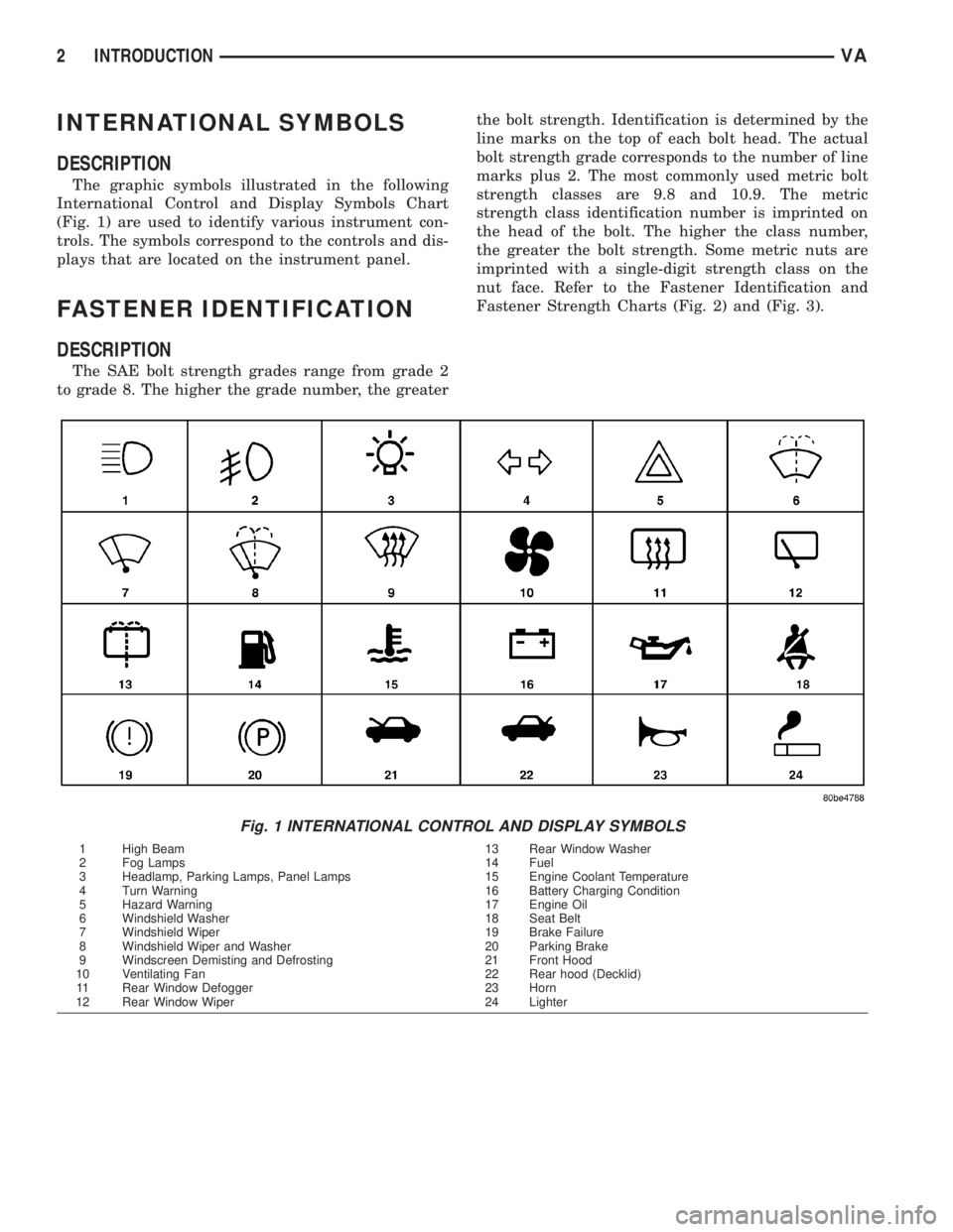
The graphic symbols illustrated in the following
International Control and Display Symbols Chart
(Fig. 1) are used to identify various instrument con-
trols. The symbols correspond to the controls and dis-
plays that are located on the instrument panel.
FASTENER IDENTIFICATION
DESCRIPTION
The SAE bolt strength grades range from grade 2
to grade 8. The higher the grade number, the greaterthe bolt strength. Identification is determined by the
line marks on the top of each bolt head. The actual
bolt strength grade corresponds to the number of line
marks plus 2. The most commonly used metric bolt
strength classes are 9.8 and 10.9. The metric
strength class identification number is imprinted on
the head of the bolt. The higher the class number,
the greater the bolt strength. Some metric nuts are
imprinted with a single-digit strength class on the
nut face. Refer to the Fastener Identification and
Fastener Strength Charts (Fig. 2) and (Fig. 3).
Fig. 1 INTERNATIONAL CONTROL AND DISPLAY SYMBOLS
1 High Beam 13 Rear Window Washer
2 Fog Lamps 14 Fuel
3 Headlamp, Parking Lamps, Panel Lamps 15 Engine Coolant Temperature
4 Turn Warning 16 Battery Charging Condition
5 Hazard Warning 17 Engine Oil
6 Windshield Washer 18 Seat Belt
7 Windshield Wiper 19 Brake Failure
8 Windshield Wiper and Washer 20 Parking Brake
9 Windscreen Demisting and Defrosting 21 Front Hood
10 Ventilating Fan 22 Rear hood (Decklid)
11 Rear Window Defogger 23 Horn
12 Rear Window Wiper 24 Lighter
2 INTRODUCTIONVA
Page 173 of 1232
arate take out and connector of the vehicle wire
harness.
Located between the rear cover and the cluster
hood is the cluster housing. The molded plastic clus-
ter housing serves as the carrier for the cluster elec-
tronic circuit board and circuitry, the cluster
connector receptacles, the gauges, a Light Emitting
Diode (LED) for each cluster indicator and general
illumination lamp, the multi-function indicator LCD
unit, electronic tone generators, the cluster overlay,
the gauge pointers, the multi-function indicator
switches and the four switch push buttons.
The cluster overlay is a laminated plastic unit. The
dark, visible, outer surface of the overlay is marked
with all of the gauge dial faces and graduations, but
this layer is also translucent. The darkness of this
outer layer prevents the cluster from appearing clut-
tered or busy by concealing the cluster indicators
that are not illuminated, while the translucence of
this layer allows those indicators and icons that are
illuminated to be readily visible. The underlying
layer of the overlay is opaque and allows light from
the LED for each of the various indicators and illu-
mination lamps behind it to be visible through the
outer layer of the overlay only through predeter-
mined cutouts. A rectangular opening in the overlay
at the base of the speedometer provides a window
through which the illuminated multi-function indica-
tor LCD unit can be viewed.
Several versions of the EMIC module are offered
on this model. These versions accommodate all of the
variations of optional equipment and regulatory
requirements for the various markets in which the
vehicle will be offered. The microprocessor-based
EMIC utilizes integrated circuitry, Electrically Eras-
able Programmable Read Only Memory (EEPROM)
type memory storage, information carried on the
Controller Area Network (CAN) data bus, along with
several hard wired analog and multiplexed inputs to
monitor systems, sensors and switches throughout
the vehicle.
In response to those inputs, the hardware and soft-
ware of the EMIC allow it to control and integrate
many electronic functions and features of the vehicle
through both hard wired outputs and the transmis-
sion of electronic message outputs to other electronic
modules in the vehicle over the CAN data bus. (Refer
to 8 - ELECTRICAL/ELECTRONIC CONTROL
MODULES/COMMUNICATION - DESCRIPTION -
CAN BUS).
Besides typical instrument cluster gauge and indi-
cator support, the electronic functions and features
that the EMIC supports or controls include the fol-
lowing:
²Active Service System- In vehicles equipped
with the Active Service SYSTem (ASSYST) engine oilmaintenance indicator option, the EMIC electronic
circuit board includes a second dedicated micropro-
cessor. This second microprocessor evaluates various
data including time, mileage, and driving conditions
to calculate the required engine oil service intervals,
and provides both visual and audible alerts to the
vehicle operator when certain engine oil maintenance
services are required.
²Audible Warnings- The EMIC electronic cir-
cuit board is equipped with an audible tone generator
and programming that allows it to provide various
audible alerts to the vehicle operator, including buzz-
ing and chime tones. An audible contactless elec-
tronic relay is also soldered onto the circuit board to
produce audible clicks that is synchronized with turn
signal indicator flashing to emulate the sounds of a
conventional turn signal or hazard warning flasher.
These audible clicks can occur at one of two rates to
emulate both normal and bulb-out turn or hazard
flasher operation. (Refer to 8 - ELECTRICAL/
CHIME/BUZZER - DESCRIPTION).
²Panel Lamps Dimming Control- The EMIC
provides a hard wired 12-volt Pulse-Width Modulated
(PWM) output that synchronizes the dimming level
of all panel lamps dimmer controlled lamps with that
of the cluster general illumination lamps and multi-
function indicator.
The EMIC houses four analog gauges and has pro-
visions for up to nineteen indicators (Fig. 3). The
EMIC includes the following analog gauges:
²Coolant Temperature Gauge
²Fuel Gauge
²Speedometer
²Tachometer
The EMIC includes provisions for the following
indicators (Fig. 3):
²Airbag (SRS) Indicator
²Antilock Brake System (ABS) Indicator
²Brake Indicator
²Brake Wear Indicator
²Charging Indicator
²Clogged Fuel Filter Indicator
²Coolant Low Indicator
²High Beam Indicator
²Low Fuel Indicator
²Malfunction Indicator Lamp (MIL)
²Multi-Function Indicator (LCD)
²Seatbelt Indicator
²Traction Control (ASR) Indicator
²Traction Control (ASR) Malfunction Indica-
tor
²Turn Signal (Right and Left) Indicators
²Washer Fluid Indicator
²Wait-To-Start Indicator
²Water-In-Fuel Indicator
VAINSTRUMENT CLUSTER 8J - 3
INSTRUMENT CLUSTER (Continued)
Page 209 of 1232
(1) Disconnect and isolate the battery negative
cable.
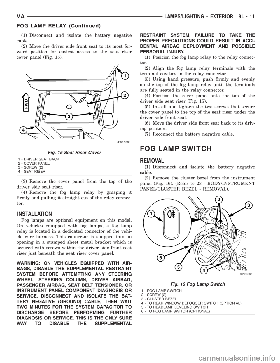
(2) Move the driver side front seat to its most for-
ward position for easiest access to the seat riser
cover panel (Fig. 15).
(3) Remove the cover panel from the top of the
driver side seat riser.
(4) Remove the fog lamp relay by grasping it
firmly and pulling it straight out of the relay connec-
tor.
INSTALLATION
Fog lamps are optional equipment on this model.
On vehicles equipped with fog lamps, a fog lamp
relay is located in a dedicated connector of the vehi-
cle wire harness. This connector is snapped into an
opening in a stamped sheet metal bracket which is
secured with screws within the driver side front seat
riser just beneath the seat riser cover panel.
WARNING: ON VEHICLES EQUIPPED WITH AIR-
BAGS, DISABLE THE SUPPLEMENTAL RESTRAINT
SYSTEM BEFORE ATTEMPTING ANY STEERING
WHEEL, STEERING COLUMN, DRIVER AIRBAG,
PASSENGER AIRBAG, SEAT BELT TENSIONER, OR
INSTRUMENT PANEL COMPONENT DIAGNOSIS OR
SERVICE. DISCONNECT AND ISOLATE THE BAT-
TERY NEGATIVE (GROUND) CABLE, THEN WAIT
TWO MINUTES FOR THE SYSTEM CAPACITOR TO
DISCHARGE BEFORE PERFORMING FURTHER
DIAGNOSIS OR SERVICE. THIS IS THE ONLY SURE
WAY TO DISABLE THE SUPPLEMENTALRESTRAINT SYSTEM. FAILURE TO TAKE THE
PROPER PRECAUTIONS COULD RESULT IN ACCI-
DENTAL AIRBAG DEPLOYMENT AND POSSIBLE
PERSONAL INJURY.
(1) Position the fog lamp relay to the relay connec-
tor.
(2) Align the fog lamp relay terminals with the
terminal cavities in the relay connector.
(3) Using hand pressure, push firmly and evenly
on the top of the fog lamp relay until the terminals
are fully seated in the relay connector.
(4) Position the cover panel onto the top of the
driver side seat riser (Fig. 15).
(5) Install and tighten the two screws that secure
the cover panel to the top of the seat riser under the
driver side front seat.
(6) Move the driver side front seat back to its driv-
ing position.
(7) Reconnect the battery negative cable.
FOG LAMP SWITCH
REMOVAL
(1) Disconnect and isolate the battery negative
cable.
(2) Remove the cluster bezel from the instrument
panel (Fig. 16). (Refer to 23 - BODY/INSTRUMENT
PANEL/CLUSTER BEZEL - REMOVAL).
Fig. 15 Seat Riser Cover
1 - DRIVER SEAT BACK
2 - COVER PANEL
3 - SCREW (2)
4 - SEAT RISER
Fig. 16 Fog Lamp Switch
1 - FOG LAMP SWITCH
2 - SCREW (2)
3 - CLUSTER BEZEL
4 - TO REAR WINDOW DEFOGGER SWITCH (OPTION AL)
5 - TO HEADLAMP LEVELING SWITCH
6 - TO FOG LAMP SWITCH (OPTIONAL)
VALAMPS/LIGHTING - EXTERIOR 8L - 11
FOG LAMP RELAY (Continued)
Page 214 of 1232
(4)Rotate the headlamp leveling motor counterclock-
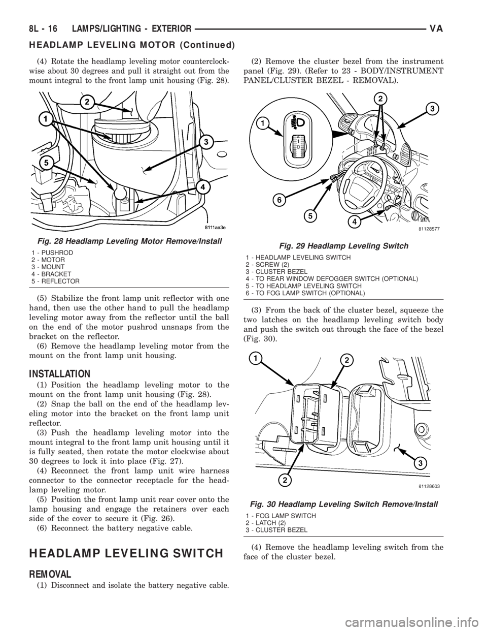
wise about 30 degrees and pull it straight out from the
mount integral to the front lamp unit housing (Fig. 28).
(5) Stabilize the front lamp unit reflector with one
hand, then use the other hand to pull the headlamp
leveling motor away from the reflector until the ball
on the end of the motor pushrod unsnaps from the
bracket on the reflector.
(6) Remove the headlamp leveling motor from the
mount on the front lamp unit housing.
INSTALLATION
(1) Position the headlamp leveling motor to the
mount on the front lamp unit housing (Fig. 28).
(2) Snap the ball on the end of the headlamp lev-
eling motor into the bracket on the front lamp unit
reflector.
(3) Push the headlamp leveling motor into the
mount integral to the front lamp unit housing until it
is fully seated, then rotate the motor clockwise about
30 degrees to lock it into place (Fig. 27).
(4) Reconnect the front lamp unit wire harness
connector to the connector receptacle for the head-
lamp leveling motor.
(5) Position the front lamp unit rear cover onto the
lamp housing and engage the retainers over each
side of the cover to secure it (Fig. 26).
(6) Reconnect the battery negative cable.
HEADLAMP LEVELING SWITCH
REMOVAL
(1)Disconnect and isolate the battery negative cable.
(2) Remove the cluster bezel from the instrument
panel (Fig. 29). (Refer to 23 - BODY/INSTRUMENT
PANEL/CLUSTER BEZEL - REMOVAL).
(3) From the back of the cluster bezel, squeeze the
two latches on the headlamp leveling switch body
and push the switch out through the face of the bezel
(Fig. 30).
(4) Remove the headlamp leveling switch from the
face of the cluster bezel.
Fig. 28 Headlamp Leveling Motor Remove/Install
1 - PUSHROD
2 - MOTOR
3 - MOUNT
4 - BRACKET
5 - REFLECTORFig. 29 Headlamp Leveling Switch
1 - HEADLAMP LEVELING SWITCH
2 - SCREW (2)
3 - CLUSTER BEZEL
4 - TO REAR WINDOW DEFOGGER SWITCH (OPTIONAL)
5 - TO HEADLAMP LEVELING SWITCH
6 - TO FOG LAMP SWITCH (OPTIONAL)
Fig. 30 Headlamp Leveling Switch Remove/Install
1 - FOG LAMP SWITCH
2 - LATCH (2)
3 - CLUSTER BEZEL
8L - 16 LAMPS/LIGHTING - EXTERIORVA
HEADLAMP LEVELING MOTOR (Continued)
Page 233 of 1232
POWER SYSTEMS
TABLE OF CONTENTS
page page
POWER LOCKS............................ 1
POWER MIRRORS......................... 3POWER WINDOWS......................... 5
POWER LOCKS
TABLE OF CONTENTS
page page
POWER LOCKS
DESCRIPTION..........................1
DOOR LOCK MOTOR
REMOVAL.............................1
INSTALLATION..........................1
REMOTE KEYLESS ENTRY TRANSMITTER
DESCRIPTION..........................2MASTER LOCK SWITCH
DESCRIPTION..........................2
DIAGNOSIS AND TESTING - MASTER LOCK
SWITCH.............................2
REMOVAL.............................2
INSTALLATION..........................2
POWER LOCKS
DESCRIPTION
CENTRAL LOCKING
The central locking system locks all vehicle doors if
any door is locked from the inside or mechanically
locked with the key from the outside. the master door
lock switch on the instrument panel enables the
operator to lock/unlock all doors.
REMOTE KEYLESS ENTRY
The SKREEM is a combination of the Remote Key-
less Entry (RKE) module and the Sentry Key Immo-
bilizer (SKIM) module. It is located behind the
instrument cluster and has an antenna that mounts
to the A-pillar.
AUTO DOOR LOCKS
Whenever the engine is started, the CTM receivers
a message to lock all doors except the drivers door.
This is accomplished through a relay. The relay is
controlled by the Instrument Cluster which receives
a command from the ECM.
ACCIDENT RESPONSE
The CTM is hardwired to the Airbag Control Mod-
ule through the Enhanced Accident Report Driver cir-
cuit. Anytime the vehicles airbags are deployed, the
CTM will unlock all doors and a ªcrashº DTC will be
stored in memory. The door locks will be inoperative
until that code is cleared.
DOOR LOCK MOTOR
REMOVAL
(1) Disconnect and isolate the battery negative
cable.
(2) Remove the door trim panel.
(3) Remove the door lock.
(4) Remove the door lock motor from the door lock.
INSTALLATION
(1) Install the door lock motor to the door lock.
(2) Install the door lock.
(3) Install the door trim panel.
(4) Connect the battery negative cable.
VAPOWER SYSTEMS 8N - 1
Page 235 of 1232
POWER MIRRORS
TABLE OF CONTENTS
page page
POWER MIRRORS
DESCRIPTION..........................3
POWER MIRROR SWITCH
DIAGNOSIS AND TESTING - POWER MIRROR
SWITCH.............................3REMOVAL.............................3
INSTALLATION..........................4
POWER MIRRORS
DESCRIPTION
The power operated outside rear view mirrors
allow the driver to adjust both outside mirrors elec-
trically from the driver side front seat position by
operating a switch on the driver side front door trim
panel. The power mirrors receive a non-switched bat-
tery feed through a fuse so that the system will
remain operational, regardless of the ignition switch
position.
POWER MIRROR SWITCH
DIAGNOSIS AND TESTING - POWER MIRROR
SWITCH
(1) Disconnect and isolate the battery negative
cable.
(2) Remove power mirror switch (Refer to 8 -
ELECTRICAL/POWER MIRRORS/POWER MIRROR
SWITCH - REMOVAL).
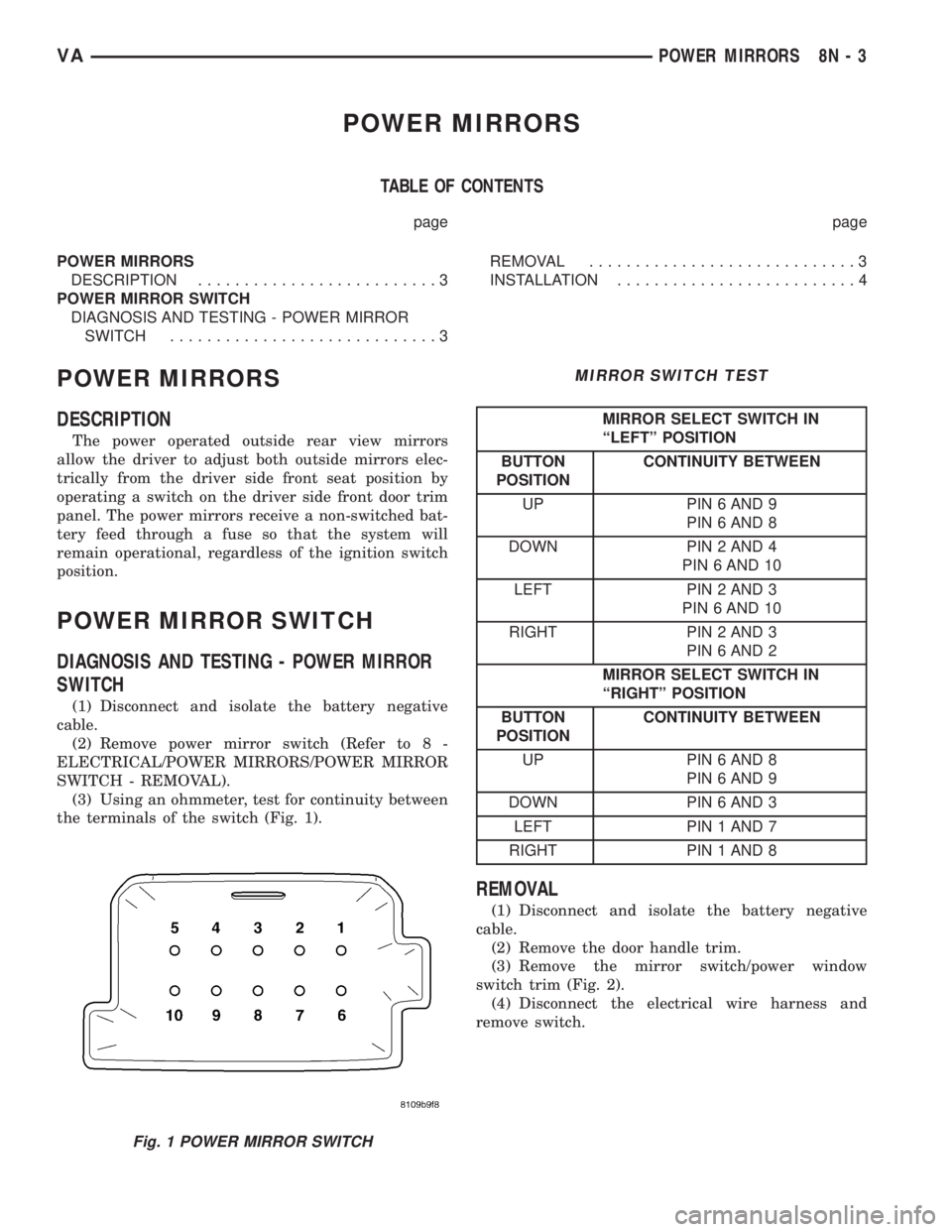
(3) Using an ohmmeter, test for continuity between
the terminals of the switch (Fig. 1).
MIRROR SWITCH TEST
MIRROR SELECT SWITCH IN
ªLEFTº POSITION
BUTTON
POSITIONCONTINUITY BETWEEN
UP PIN 6 AND 9
PIN 6 AND 8
DOWN PIN 2 AND 4
PIN 6 AND 10
LEFT PIN 2 AND 3
PIN 6 AND 10
RIGHT PIN 2 AND 3
PIN 6 AND 2
MIRROR SELECT SWITCH IN
ªRIGHTº POSITION
BUTTON
POSITIONCONTINUITY BETWEEN
UP PIN 6 AND 8
PIN 6 AND 9
DOWN PIN 6 AND 3
LEFT PIN 1 AND 7
RIGHT PIN 1 AND 8
REMOVAL
(1) Disconnect and isolate the battery negative
cable.
(2) Remove the door handle trim.
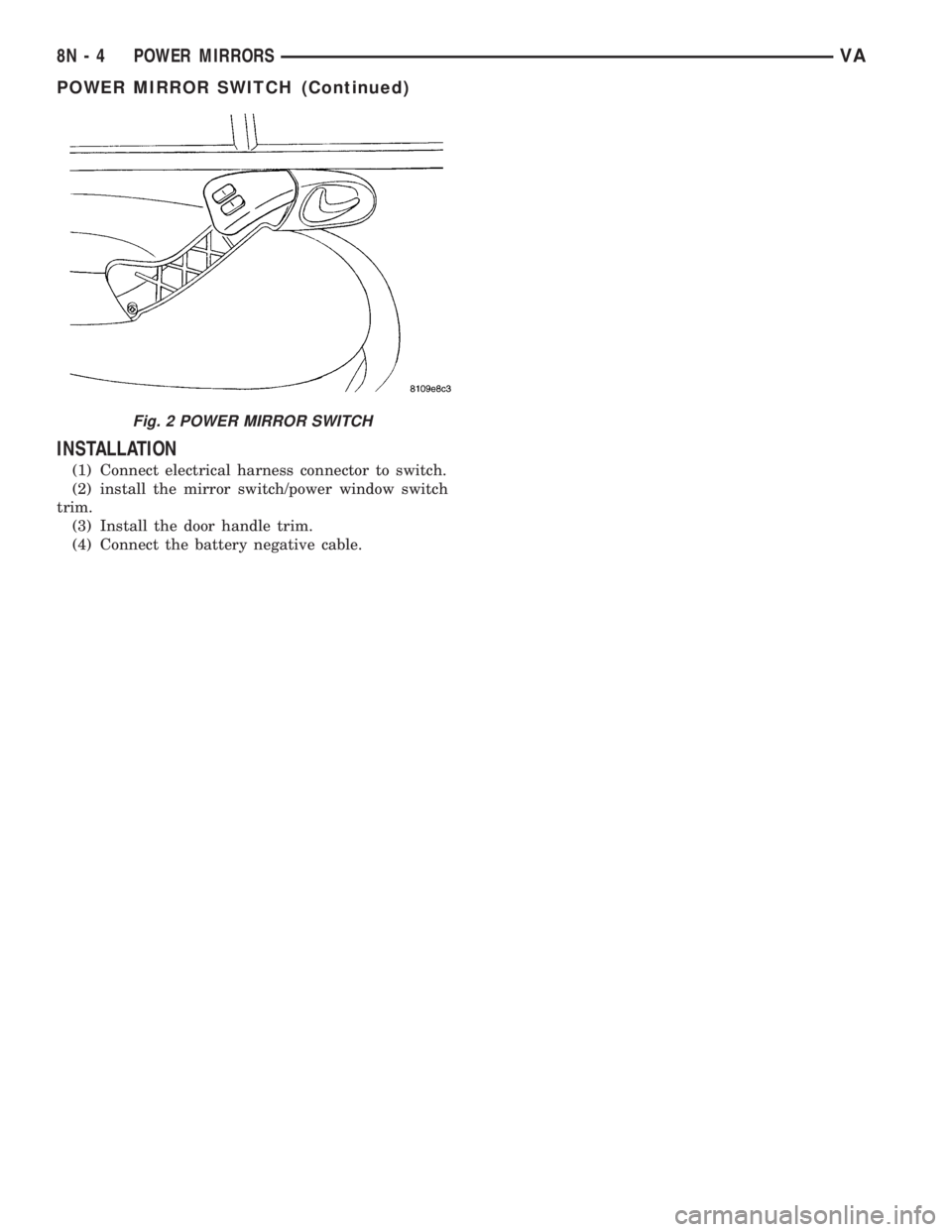
(3) Remove the mirror switch/power window
switch trim (Fig. 2).
(4) Disconnect the electrical wire harness and
remove switch.
Fig. 1 POWER MIRROR SWITCH
VAPOWER MIRRORS 8N - 3
Page 236 of 1232
INSTALLATION
(1) Connect electrical harness connector to switch.
(2) install the mirror switch/power window switch
trim.
(3) Install the door handle trim.
(4) Connect the battery negative cable.
Fig. 2 POWER MIRROR SWITCH
8N - 4 POWER MIRRORSVA
POWER MIRROR SWITCH (Continued)
Page 237 of 1232
POWER WINDOWS
TABLE OF CONTENTS
page page
POWER WINDOWS
DESCRIPTION..........................5
OPERATION............................5
WINDOW MOTOR
REMOVAL.............................5POWER WINDOW SWITCH
DIAGNOSIS AND TESTING - POWER
WINDOW SWITCH......................5
REMOVAL.............................6
INSTALLATION..........................6
POWER WINDOWS
DESCRIPTION
The power window system allows each of the door
windows to be raised and lowered electrically by
actuating a switch on each door panel. A master
switch on the drivers door allows the driver to raise
or lower each door window. The power window sys-
tem operates only when the ignition switch is in the
RUN or ACCESSORY position.
OPERATION
WINDOW SWITCH
The power window switches control the battery
and ground feeds to the power window motors. The
passenger door power window switches receive their
battery and ground feeds through the circuitry of the
drivers window switch.
WINDOW MOTOR
Window motors use permanent type magnets. The
B+ and ground applied at the motor terminal pins
will cause the motor to rotate in one direction.
Reversing current through the motor terminals will
cause the motor to rotate in the opposite direction.
Refer to the appropriate wiring information. The
wiring information includes wiring diagrams, proper
wire and connector repair procedures, details of wire
harness routing and retention, connector pin-out
information and location views for the various wire
harness connectors, splices and grounds.
WINDOW MOTOR
REMOVAL
The window motor is serviced with the window
regulator.
POWER WINDOW SWITCH
DIAGNOSIS AND TESTING - POWER WINDOW
SWITCH
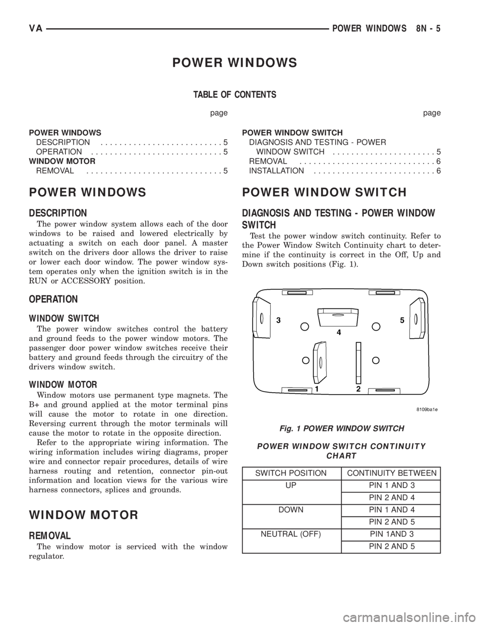
Test the power window switch continuity. Refer to
the Power Window Switch Continuity chart to deter-
mine if the continuity is correct in the Off, Up and
Down switch positions (Fig. 1).
POWER WINDOW SWITCH CONTINUITY
CHART
SWITCH POSITION CONTINUITY BETWEEN
UP PIN 1 AND 3
PIN 2 AND 4
DOWN PIN 1 AND 4
PIN 2 AND 5
NEUTRAL (OFF) PIN 1AND 3
PIN 2 AND 5
Fig. 1 POWER WINDOW SWITCH
VAPOWER WINDOWS 8N - 5