2005 MERCEDES-BENZ SPRINTER WATER PUMP REMOVAL
[x] Cancel search: WATER PUMP REMOVALPage 101 of 1232
ACCESSORY DRIVE
TABLE OF CONTENTS
page page
BELT TENSIONERS
DESCRIPTION..........................5
OPERATION............................5
DRIVE BELTS
DIAGNOSIS AND TESTING - ACCESSORY
DRIVE BELT..........................5REMOVAL.............................8
INSTALLATION..........................8
BELT TENSIONERS
DESCRIPTION
CAUTION: Do not attempt to check belt tension with
a belt tension gauge on vehicles equipped with an
automatic belt tensioner.
Drive belts on all engines are equipped with a
spring loaded automatic belt tensioner. This ten-
sioner maintains constant belt tension at all times
and requires no maintenance or adjustment.
OPERATION
WARNING: THE AUTOMATIC BELT TENSIONER
ASSEMBLY IS SPRING LOADED. DO NOT ATTEMPT
TO DISASSEMBLE THE TENSIONER ASSEMBLY.
The automatic belt tensioner maintains correct belt
tension using a coiled spring within the tensioner
housing. The spring applies pressure to the tensioner
arm pressing the arm into the belt, tensioning the
belt.
If a new belt is being installed, the arrow must be
within approximately 3 mm (1/8 in.) of indexing
mark. Belt is considered new if it has been used 15
minutes or less. If this specification cannot be met,
check for:
²The wrong belt being installed (incorrect length/
width)
²Worn bearings on an engine accessory (A/C com-
pressor, power steering pump, water pump, idler pul-
ley or generator)
²A pulley on an engine accessory being loose
²Misalignment of an engine accessory
²Belt incorrectly routed.
DRIVE BELTS
DIAGNOSIS AND TESTING - ACCESSORY
DRIVE BELT
VISUAL DIAGNOSIS
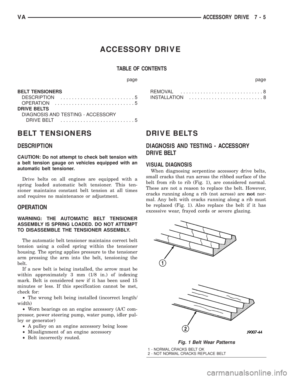
When diagnosing serpentine accessory drive belts,
small cracks that run across the ribbed surface of the
belt from rib to rib (Fig. 1), are considered normal.
These are not a reason to replace the belt. However,
cracks running along a rib (not across) arenotnor-
mal. Any belt with cracks running along a rib must
be replaced (Fig. 1). Also replace the belt if it has
excessive wear, frayed cords or severe glazing.
Fig. 1 Belt Wear Patterns
1 - NORMAL CRACKS BELT OK
2 - NOT NORMAL CRACKS REPLACE BELT
VAACCESSORY DRIVE 7 - 5
Page 104 of 1232
REMOVAL
CAUTION: Do not attempt to check belt tension with
a belt tension gauge on vehicles equipped with an
automatic belt tensioner.
NOTE: The belt routing schematics are published
from the latest information available at the time of
publication. If anything differs between these sche-
matics and the Belt Routing Label, use the sche-
matics on Belt Routing Label.This label is located in
the engine compartment.
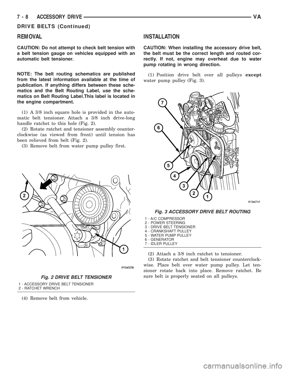
(1) A 3/8 inch square hole is provided in the auto-
matic belt tensioner. Attach a 3/8 inch drive-long
handle ratchet to this hole (Fig. 2).
(2) Rotate ratchet and tensioner assembly counter-
clockwise (as viewed from front) until tension has
been relieved from belt (Fig. 2).
(3) Remove belt from water pump pulley first.
(4) Remove belt from vehicle.
INSTALLATION
CAUTION: When installing the accessory drive belt,
the belt must be the correct length and routed cor-
rectly. If not, engine may overheat due to water
pump rotating in wrong direction.
(1) Position drive belt over all pulleysexcept
water pump pulley (Fig. 3).
(2) Attach a 3/8 inch ratchet to tensioner.
(3) Rotate ratchet and belt tensioner counterclock-
wise. Place belt over water pump pulley. Let ten-
sioner rotate back into place. Remove ratchet. Be
sure belt is properly seated on all pulleys.
Fig. 2 DRIVE BELT TENSIONER
1 - ACCESSORY DRIVE BELT TENSIONER
2 - RATCHET WRENCH
Fig. 3 ACCESSORY DRIVE BELT ROUTING
1 - A/C COMPRESSOR
2 - POWER STEERING
3 - DRIVE BELT TENSIONER
4 - CRANKSHAFT PULLEY
5 - WATER PUMP PULLEY
6 - GENERATOR
7 - IDLER PULLEY
7 - 8 ACCESSORY DRIVEVA
DRIVE BELTS (Continued)
Page 105 of 1232
ENGINE
TABLE OF CONTENTS
page page
COOLANT
DESCRIPTION..........................9
DIAGNOSIS AND TESTING - COOLING
SYSTEM LEAKS......................10
STANDARD PROCEDURE
STANDARD PROCEDURE - ADDING
ADDITIONAL COOLANT.................11
STANDARD PROCEDURE - DRAINING
COOLING SYSTEM....................12
STANDARD PROCEDURE - REFILLING
COOLING SYSTEM....................12
COOLANT LEVEL SENSOR
REMOVAL.............................13
INSTALLATION.........................13
RADIATOR FAN
REMOVAL.............................13
INSTALLATION.........................13
ENGINE BLOCK HEATER
REMOVAL.............................14
INSTALLATION.........................14
ENGINE COOLANT TEMP SENSOR
DESCRIPTION.........................14REMOVAL.............................14
INSTALLATION.........................15
ENGINE COOLANT THERMOSTAT
REMOVAL.............................15
INSTALLATION.........................16
FAN DRIVE VISCOUS CLUTCH
REMOVAL.............................16
INSTALLATION.........................16
RADIATOR
REMOVAL.............................16
INSTALLATION.........................17
RADIATOR PRESSURE CAP
DESCRIPTION.........................18
OPERATION...........................18
DIAGNOSIS AND TESTING - RADIATOR
PRESSURE CAP......................19
WATER PUMP
REMOVAL.............................19
INSTALLATION.........................20
COOLANT
DESCRIPTION
Coolant flows through the engine water jackets and
cylinder heads absorbing heat produced by the engine
during operation. The coolant carries heat to the radia-
tor and heater core. Here it is transferred to ambient
air passing through the radiator and heater core fins.
The required ethylene-glycol (antifreeze) and water
mixture depends upon the climate and vehicle oper-
ating conditions. The recommended mixture of 50/50
ethylene-glycol and water will provide protection
against freezing to -37 deg. C (-35 deg. F). The anti-
freeze concentrationmust alwaysbe a minimum of
44 percent, year-round in all climates.If percentage
is lower than 44 percent, engine parts may be
eroded by cavitation, and cooling system com-
ponents may be severely damaged by corrosion.
Maximum protection against freezing is provided
with a 68 percent antifreeze concentration, which
prevents freezing down to -67.7 deg. C (-90 deg. F). A
higher percentage will freeze at a warmer tempera-
ture. Also, a higher percentage of antifreeze can
cause the engine to overheat because the specific
heat of antifreeze is lower than that of water.100 Percent Ethylene-GlycolÐShould Not Be Used in
Chrysler Vehicles
Use of 100 percent ethylene-glycol will cause forma-
tion of additive deposits in the system, as the corrosion
inhibitive additives in ethylene-glycol require the pres-
ence of water to dissolve. The deposits act as insulation,
causing temperatures to rise to as high as 149 deg. C
(300 deg. F). This temperature is hot enough to melt
plastic and soften solder. The increased temperature can
result in engine detonation. In addition, 100 percent
ethylene-glycol freezes at -22 deg. C (-8 deg. F ).
Propylene-glycol FormulationsÐShould Not Be Used in
Chrysler Vehicles
Propylene-glycol formulations do not meet
Chrysler coolant specifications.
It's overall effec-
tive temperature range is smaller than that of ethylene-
glycol. The freeze point of 50/50 propylene-glycol and
water is -32 deg. C (-26 deg. F). 5 deg. C higher than
ethylene-glycol's freeze point. The boiling point (protec-
tion against summer boil-over) of propylene-glycol is 125
deg. C (257 deg.F)at96.5 kPa (14 psi), compared to
128 deg. C (263 deg. F) for ethylene-glycol. Use of pro-
pylene-glycol can result in boil-over or freeze-up in
Chrysler vehicles, which are designed for ethylene-gly-
col. Propylene glycol also has poorer heat transfer char-
VAENGINE 7 - 9
Page 107 of 1232
Operate tester pump to apply 103.4 kPa (15 psi)
pressure to system. If hoses enlarge excessively or
bulges while testing, replace as necessary. Observe
gauge pointer and determine condition of cooling sys-
tem according to following criteria:
Holds Steady:If pointer remains steady for two
minutes, serious coolant leaks are not present in sys-
tem. However, there could be an internal leak that
does not appear with normal system test pressure. If
it is certain that coolant is being lost and leaks can-
not be detected, inspect for interior leakage or per-
form Internal Leakage Test.
Drops Slowly:Indicates a small leak or seepage
is occurring. Examine all connections for seepage or
slight leakage with a flashlight. Inspect radiator,
hoses, gasket edges and heater. Seal small leak holes
with a Sealer Lubricant (or equivalent). Repair leak
holes and inspect system again with pressure
applied.
Drops Quickly:Indicates that serious leakage is
occurring. Examine system for external leakage. If
leaks are not visible, inspect for internal leakage.
Large radiator leak holes should be repaired by a
reputable radiator repair shop.
INTERNAL LEAKAGE INSPECTION
Remove engine oil pan drain plug and drain a
small amount of engine oil. If coolant is present in
the pan, it will drain first because it is heavier than
oil. An alternative method is to operate engine for a
short period to churn the oil. After this is done,
remove engine dipstick and inspect for water glob-
ules. Also inspect transmission dipstick for water
globules and transmission fluid cooler for leakage.
WARNING: WITH RADIATOR PRESSURE TESTER
TOOL INSTALLED ON RADIATOR, DO NOT ALLOW
PRESSURE TO EXCEED 110 KPA (20 PSI). PRES-
SURE WILL BUILD UP QUICKLY IF A COMBUSTION
LEAK IS PRESENT. TO RELEASE PRESSURE,
ROCK TESTER FROM SIDE TO SIDE. WHEN
REMOVING TESTER, DO NOT TURN TESTER MORE
THAN 1/2 TURN IF SYSTEM IS UNDER PRESSURE.
Operate engine without pressure cap on coolant
container until thermostat opens. Attach a Pressure
Tester to container. If pressure builds up quickly it
indicates a combustion leak exists. This is usually
the result of a cylinder head gasket leak or crack in
engine. Repair as necessary.
If there is not an immediate pressure increase,
pump the Pressure Tester. Do this until indicated
pressure is within system range of 110 kPa (16 psi).
Fluctuation of gauge pointer indicates compression or
combustion leakage into cooling system.Because the vehicle is equipped with a catalytic
converter,do notremove spark plug cables or short
out cylinders to isolate compression leak.
If the needle on dial of pressure tester does not
fluctuate, race engine a few times to check for an
abnormal amount of coolant or steam. This would be
emitting from exhaust pipe. Coolant or steam from
exhaust pipe may indicate a faulty cylinder head gas-
ket, cracked engine cylinder block or cylinder head.
A convenient check for exhaust gas leakage into
cooling system is provided by a commercially avail-
able Block Leak Check tool. Follow manufacturers
instructions when using this product.
COMBUSTION LEAKAGE TEST - WITHOUT
PRESSURE TESTER
DO NOT WASTE reusable coolant. If solution is
clean, drain coolant into a clean and suitably marked
container for reuse.
WARNING: DO NOT REMOVE CYLINDER BLOCK
DRAIN PLUGS OR LOOSEN RADIATOR DRAIN
WITH SYSTEM HOT AND UNDER PRESSURE. SERI-
OUS BURNS FROM COOLANT CAN OCCUR.
Drain sufficient coolant to allow thermostat removal.
Remove accessory drive belt.
Add coolant to pressure container to bring level to
within 6.3 mm (1/4 in) of top of thermostat housing.
CAUTION: Avoid overheating. Do not operate
engine for an excessive period of time. Open drain-
cock immediately after test to eliminate boil over.
Start engine and accelerate rapidly three times, to
approximately 3000 rpm while observing coolant. If
internal engine combustion gases are leaking into
cooling system, bubbles will appear in coolant. If bub-
bles do not appear, internal combustion gas leakage
is not present.
STANDARD PROCEDURE
STANDARD PROCEDURE - ADDING
ADDITIONAL COOLANT
The use of aluminum cylinder blocks, cylinder
heads and water pumps requires special corrosion
protection. Only MopartAntifreeze/Coolant, 5
Year/100,000 Mile Formula (glycol base coolant with
corrosion inhibitors called HOAT, for Hybrid Organic
Additive Technology) is recommended. This coolant
offers the best engine cooling without corrosion when
mixed with 50% distilled water to obtain to obtain a
freeze point of -37ÉC (-35ÉF). If it loses color or
becomes contaminated, drain, flush, and replace with
fresh properly mixed coolant solution.
VAENGINE 7 - 11
COOLANT (Continued)
Page 109 of 1232
COOLANT LEVEL SENSOR
REMOVAL
WARNING: RISK OF INJURY TO SKIN AND EYES
DUE TO SCALDING FROM HOT COOLANT. DO NOT
OPEN THE COOLING SYSTEM UNLESS THE TEM-
PERATURE IS BELOW 194ÉF (90ÉC). WEAR PRO-
TECTIVE CLOTHING AND EYE WEAR. RISK OF
POISONING IF COOLANT IS SWALLOWED. STORE
COOLANT IN PROPER AND APPROPRIATELY
MARKED CONTAINERS.
NOTE: Drain coolant from radiator drain plug only.
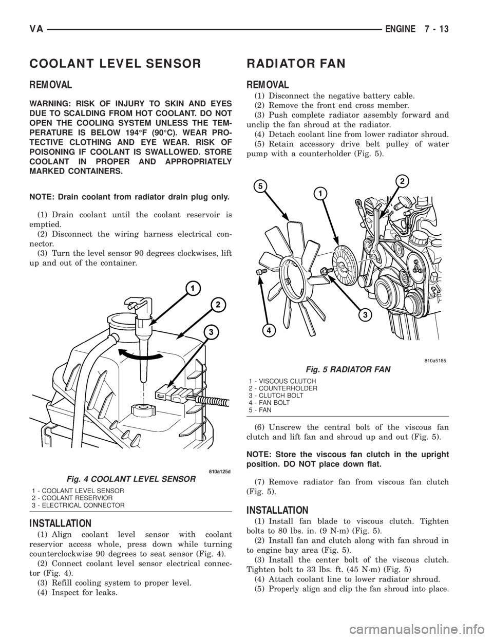
(1) Drain coolant until the coolant reservoir is
emptied.
(2) Disconnect the wiring harness electrical con-
nector.
(3) Turn the level sensor 90 degrees clockwises, lift
up and out of the container.
INSTALLATION
(1) Align coolant level sensor with coolant
reservior access whole, press down while turning
counterclockwise 90 degrees to seat sensor (Fig. 4).
(2) Connect coolant level sensor electrical connec-
tor (Fig. 4).
(3) Refill cooling system to proper level.
(4) Inspect for leaks.
RADIATOR FAN
REMOVAL
(1) Disconnect the negative battery cable.
(2) Remove the front end cross member.
(3) Push complete radiator assembly forward and
unclip the fan shroud at the radiator.
(4) Detach coolant line from lower radiator shroud.
(5) Retain accessory drive belt pulley of water
pump with a counterholder (Fig. 5).
(6) Unscrew the central bolt of the viscous fan
clutch and lift fan and shroud up and out (Fig. 5).
NOTE: Store the viscous fan clutch in the upright
position. DO NOT place down flat.
(7) Remove radiator fan from viscous fan clutch
(Fig. 5).
INSTALLATION
(1) Install fan blade to viscous clutch. Tighten
bolts to 80 lbs. in. (9 N´m) (Fig. 5).
(2) Install fan and clutch along with fan shroud in
to engine bay area (Fig. 5).
(3) Install the center bolt of the viscous clutch.
Tighten bolt to 33 lbs. ft. (45 N´m) (Fig. 5)
(4) Attach coolant line to lower radiator shroud.
(5)
Properly align and clip the fan shroud into place.
Fig. 4 COOLANT LEVEL SENSOR
1 - COOLANT LEVEL SENSOR
2 - COOLANT RESERVIOR
3 - ELECTRICAL CONNECTOR
Fig. 5 RADIATOR FAN
1 - VISCOUS CLUTCH
2 - COUNTERHOLDER
3 - CLUTCH BOLT
4 - FAN BOLT
5-FAN
VAENGINE 7 - 13
Page 115 of 1232
DIAGNOSIS AND TESTING - RADIATOR
PRESSURE CAP
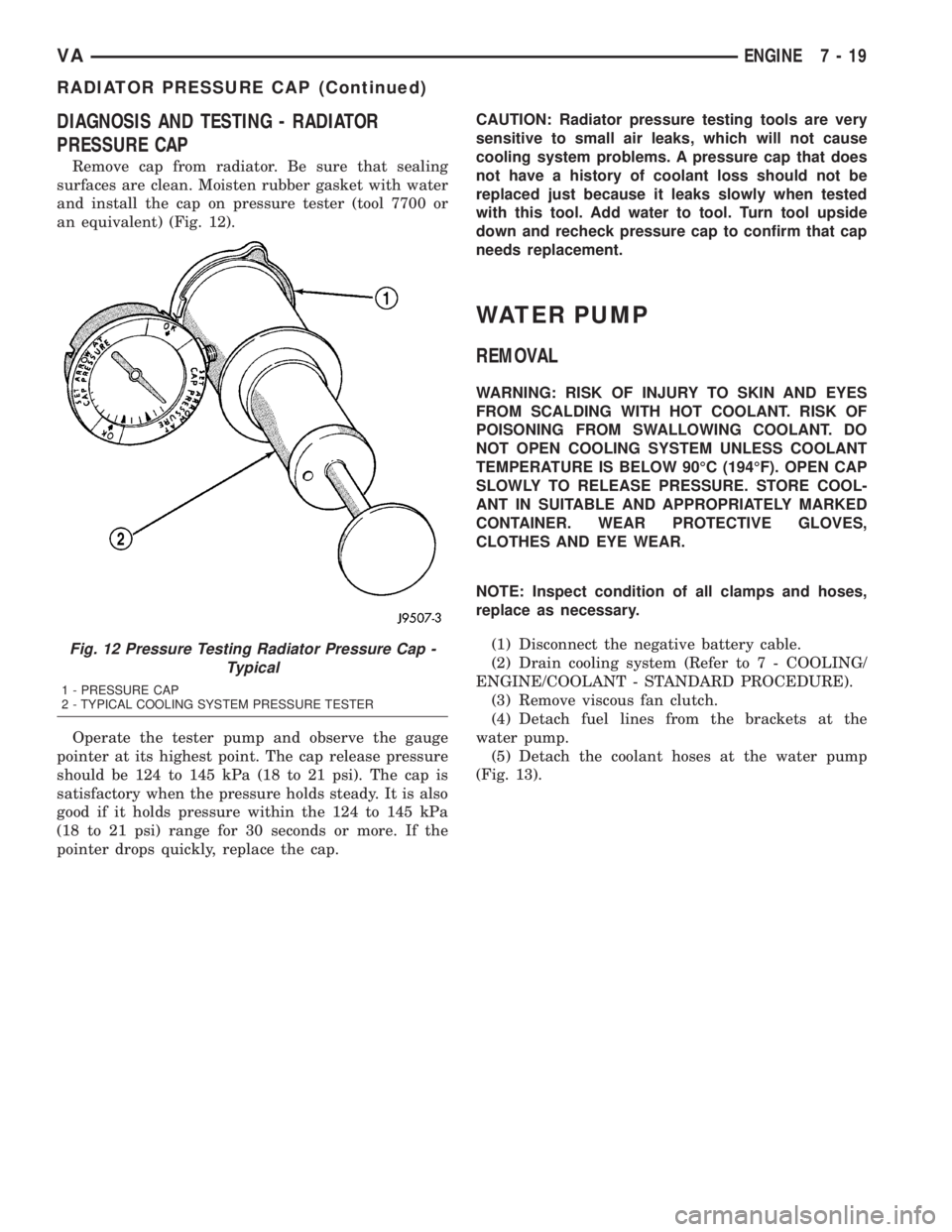
Remove cap from radiator. Be sure that sealing
surfaces are clean. Moisten rubber gasket with water
and install the cap on pressure tester (tool 7700 or
an equivalent) (Fig. 12).
Operate the tester pump and observe the gauge
pointer at its highest point. The cap release pressure
should be 124 to 145 kPa (18 to 21 psi). The cap is
satisfactory when the pressure holds steady. It is also
good if it holds pressure within the 124 to 145 kPa
(18 to 21 psi) range for 30 seconds or more. If the
pointer drops quickly, replace the cap.CAUTION: Radiator pressure testing tools are very
sensitive to small air leaks, which will not cause
cooling system problems. A pressure cap that does
not have a history of coolant loss should not be
replaced just because it leaks slowly when tested
with this tool. Add water to tool. Turn tool upside
down and recheck pressure cap to confirm that cap
needs replacement.
WATER PUMP
REMOVAL
WARNING: RISK OF INJURY TO SKIN AND EYES
FROM SCALDING WITH HOT COOLANT. RISK OF
POISONING FROM SWALLOWING COOLANT. DO
NOT OPEN COOLING SYSTEM UNLESS COOLANT
TEMPERATURE IS BELOW 90ÉC (194ÉF). OPEN CAP
SLOWLY TO RELEASE PRESSURE. STORE COOL-
ANT IN SUITABLE AND APPROPRIATELY MARKED
CONTAINER. WEAR PROTECTIVE GLOVES,
CLOTHES AND EYE WEAR.
NOTE: Inspect condition of all clamps and hoses,
replace as necessary.
(1) Disconnect the negative battery cable.
(2) Drain cooling system (Refer to 7 - COOLING/
ENGINE/COOLANT - STANDARD PROCEDURE).
(3) Remove viscous fan clutch.
(4) Detach fuel lines from the brackets at the
water pump.
(5) Detach the coolant hoses at the water pump
(Fig. 13).
Fig. 12 Pressure Testing Radiator Pressure Cap -
Typical
1 - PRESSURE CAP
2 - TYPICAL COOLING SYSTEM PRESSURE TESTER
VAENGINE 7 - 19
RADIATOR PRESSURE CAP (Continued)
Page 146 of 1232
GENERATOR
DESCRIPTION
The generator is belt-driven by the engine using a
serpentine-type drive belt. It is serviced only as a
complete assembly. If the generator fails for any rea-
son, the entire assembly must be replaced.
On certain engines, the decoupler pulley may be
replaced separately.
OPERATION
As the energized rotor begins to rotate within the
generator, the spinning magnetic field induces a cur-
rent into the windings of the stator coil. Once the
generator begins producing sufficient current, it also
provides the current needed to energize the rotor.
The stator winding connections deliver the induced
AC current to 3 positive and 3 negative diodes for
rectification. From the diodes, rectified DC current is
delivered to the vehicle electrical system through the
generator battery terminal.
Although the generators appear the same exter-
nally, different generators with different output rat-
ings are used on this vehicle. Be certain that the
replacement generator has the same output rating
and part number as the original unit. Refer to Spec-
ifications and see Generator Ratings for amperage
ratings and part numbers.
Noise emitting from the generator may be caused
by: worn, loose or defective bearings; a loose or defec-
tive drive pulley (decoupler pulley); incorrect, worn,
damaged or misadjusted fan drive belt; loose mount-
ing bolts; a misaligned drive pulley or a defective sta-
tor or diode.
An instrument panel mounted, battery charge indi-
cator lamp is used. When the key is in the on posi-
tion, the lamp will be illuminated. This is done as a
bulb check. If this lamp remains illuminated while
the engine is running, a Diagnostic Trouble Code
(DTC) has been detected for the charging system.
REMOVAL
CAUTION: DISCONNECT NEGATIVE CABLE FROM
BATTERY BEFORE REMOVING BATTERY OUTPUT
WIRE FROM GENERATOR. FAILURE TO DO SO
CAN RESULT IN INJURY.
CAUTION: Never force a belt over a pulley rim
using a screwdriver. The synthetic fiber of the belt
can be damaged.
CAUTION: When installing a serpentine accessory
drive belt, the belt MUST be routed correctly. The
water pump will be rotating in the wrong direction ifthe belt is installed incorrectly, causing the engine
to overheat. Refer to belt routing label in engine
compartment, or refer to Belt Schematics in Cooling
System.
(1) Disconnect and isolate negative battery cable.
(2) Remove generator drive belt. Refer to Cooling
System for procedure.
(3) Raise and support vehicle.
(4) Remove protective plastic cover from B+ stud
at top of generator.
(5) Remove nut securing battery output cable to
B+ terminal at top of generator.
(6) Unplug field terminal connector at rear of gen-
erator.
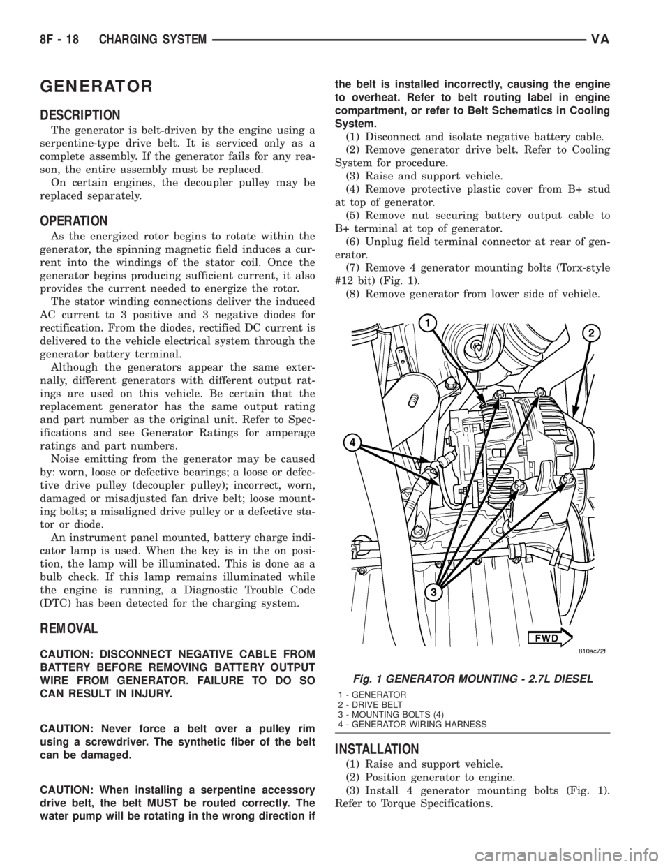
(7) Remove 4 generator mounting bolts (Torx-style
#12 bit) (Fig. 1).
(8) Remove generator from lower side of vehicle.
INSTALLATION
(1) Raise and support vehicle.
(2) Position generator to engine.
(3) Install 4 generator mounting bolts (Fig. 1).
Refer to Torque Specifications.
Fig. 1 GENERATOR MOUNTING - 2.7L DIESEL
1 - GENERATOR
2 - DRIVE BELT
3 - MOUNTING BOLTS (4)
4 - GENERATOR WIRING HARNESS
8F - 18 CHARGING SYSTEMVA
Page 289 of 1232
CHECK VALVE
DESCRIPTION
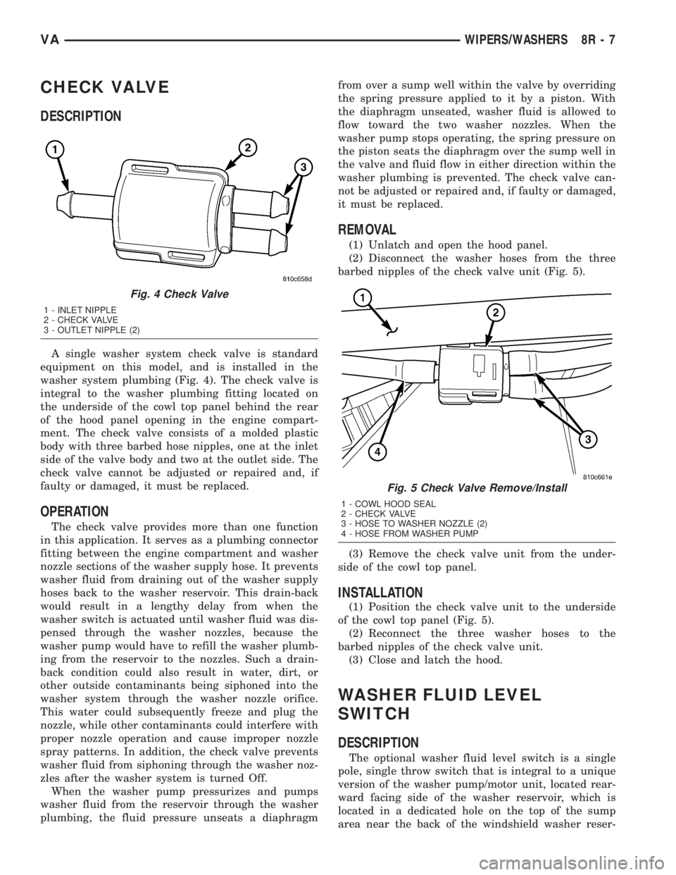
A single washer system check valve is standard
equipment on this model, and is installed in the
washer system plumbing (Fig. 4). The check valve is
integral to the washer plumbing fitting located on
the underside of the cowl top panel behind the rear
of the hood panel opening in the engine compart-
ment. The check valve consists of a molded plastic
body with three barbed hose nipples, one at the inlet
side of the valve body and two at the outlet side. The
check valve cannot be adjusted or repaired and, if
faulty or damaged, it must be replaced.
OPERATION
The check valve provides more than one function
in this application. It serves as a plumbing connector
fitting between the engine compartment and washer
nozzle sections of the washer supply hose. It prevents
washer fluid from draining out of the washer supply
hoses back to the washer reservoir. This drain-back
would result in a lengthy delay from when the
washer switch is actuated until washer fluid was dis-
pensed through the washer nozzles, because the
washer pump would have to refill the washer plumb-
ing from the reservoir to the nozzles. Such a drain-
back condition could also result in water, dirt, or
other outside contaminants being siphoned into the
washer system through the washer nozzle orifice.
This water could subsequently freeze and plug the
nozzle, while other contaminants could interfere with
proper nozzle operation and cause improper nozzle
spray patterns. In addition, the check valve prevents
washer fluid from siphoning through the washer noz-
zles after the washer system is turned Off.
When the washer pump pressurizes and pumps
washer fluid from the reservoir through the washer
plumbing, the fluid pressure unseats a diaphragmfrom over a sump well within the valve by overriding
the spring pressure applied to it by a piston. With
the diaphragm unseated, washer fluid is allowed to
flow toward the two washer nozzles. When the
washer pump stops operating, the spring pressure on
the piston seats the diaphragm over the sump well in
the valve and fluid flow in either direction within the
washer plumbing is prevented. The check valve can-
not be adjusted or repaired and, if faulty or damaged,
it must be replaced.
REMOVAL
(1) Unlatch and open the hood panel.
(2) Disconnect the washer hoses from the three
barbed nipples of the check valve unit (Fig. 5).
(3) Remove the check valve unit from the under-
side of the cowl top panel.
INSTALLATION
(1) Position the check valve unit to the underside
of the cowl top panel (Fig. 5).
(2) Reconnect the three washer hoses to the
barbed nipples of the check valve unit.
(3) Close and latch the hood.
WASHER FLUID LEVEL
SWITCH
DESCRIPTION
The optional washer fluid level switch is a single
pole, single throw switch that is integral to a unique
version of the washer pump/motor unit, located rear-
ward facing side of the washer reservoir, which is
located in a dedicated hole on the top of the sump
area near the back of the windshield washer reser-
Fig. 4 Check Valve
1 - INLET NIPPLE
2 - CHECK VALVE
3 - OUTLET NIPPLE (2)
Fig. 5 Check Valve Remove/Install
1 - COWL HOOD SEAL
2 - CHECK VALVE
3 - HOSE TO WASHER NOZZLE (2)
4 - HOSE FROM WASHER PUMP
VAWIPERS/WASHERS 8R - 7