2005 MERCEDES-BENZ SPRINTER lug pattern
[x] Cancel search: lug patternPage 287 of 1232

and methods. Proper testing of the intermittent wipe
logic circuitry within the fuse block requires the use
of a DRBIIItscan tool. Refer to the appropriate diag-
nostic information. Refer to the owner's manual in
the vehicle glove box for more information on the fea-
tures and operation of the wiper and washer system.
DIAGNOSIS AND TESTING - WIPER &
WASHER SYSTEM
If the wiper motor operates, but the wipers do not
move on the windshield, replace the faulty wiper
linkage module. If the washer pump/motor operates,
but no washer fluid is dispensed on the glass; or, if
the wipers operate, but chatter, lift, or do not clear
the glass, clean and inspect the wiper and washer
system components as required. (Refer to 8 - ELEC-
TRICAL/WIPERS/WASHERS - CLEANING) and
(Refer to 8 - ELECTRICAL/WIPERS/WASHERS -
INSPECTION). For diagnosis and testing of the
multi-function switch (Refer to 8 - ELECTRICAL/
LAMPS/LIGHTING - EXTERIOR/MULTI-FUNC-
TION SWITCH - DIAGNOSIS AND TESTING).
Refer to the appropriate wiring information. The wir-
ing information includes wiring diagrams, proper
wire and connector repair procedures, details of wire
harness routing and retention, connector pin-out
information and location views for the various wire
harness connectors, splices and grounds.
The hard wired circuits and components of the
wiper and washer system may be diagnosed and
tested using conventional diagnostic tools and proce-
dures. However, conventional diagnostic methods
may not prove conclusive in the diagnosis of the
intermittent wipe logic circuitry contained within the
fuse block underneath the steering column. The most
reliable, efficient, and accurate means to diagnose
the intermittent wipe logic circuitry requires the use
of a DRBIIItscan tool. Refer to the appropriate diag-
nostic information.
WARNING: ON VEHICLES EQUIPPED WITH AIR-
BAGS, DISABLE THE SUPPLEMENTAL RESTRAINT
SYSTEM BEFORE ATTEMPTING ANY STEERING
WHEEL, STEERING COLUMN, DRIVER AIRBAG,
PASSENGER AIRBAG, SEAT BELT TENSIONER, OR
INSTRUMENT PANEL COMPONENT DIAGNOSIS OR
SERVICE. DISCONNECT AND ISOLATE THE BAT-
TERY NEGATIVE (GROUND) CABLE, THEN WAIT
TWO MINUTES FOR THE SYSTEM CAPACITOR TO
DISCHARGE BEFORE PERFORMING FURTHER
DIAGNOSIS OR SERVICE. THIS IS THE ONLY SURE
WAY TO DISABLE THE SUPPLEMENTAL
RESTRAINT SYSTEM. FAILURE TO TAKE THE
PROPER PRECAUTIONS COULD RESULT IN ACCI-
DENTAL AIRBAG DEPLOYMENT AND POSSIBLE
PERSONAL INJURY.
CLEANING - WIPER & WASHER SYSTEM
WIPER SYSTEM
The squeegees of wiper blades exposed to the ele-
ments for a long time tend to lose their wiping effec-
tiveness. Periodic cleaning of the squeegees is
suggested to remove any deposits of salt or road film.
The wiper blades, arms, and windshield glass should
only be cleaned using a sponge or soft cloth and
windshield washer fluid, a mild detergent, or a non-
abrasive cleaner. If the wiper blades continue to
leave streaks, smears, hazing, or beading on the
glass after thorough cleaning of the squeegees and
the glass, the entire wiper blade assembly must be
replaced.
CAUTION: Protect the rubber squeegees of the
wiper blades from any petroleum-based cleaners,
solvents, or contaminants. These products can rap-
idly deteriorate the rubber squeegees.
WASHER SYSTEM
If the washer system is contaminated with foreign
material, drain the washer reservoir by removing the
washer pump/motor from the reservoir. Clean foreign
material from the inside of the washer pump/motor
inlet nipple and the washer reservoir using clean
washer fluid, a mild detergent, or a non-abrasive
cleaner. Flush foreign material from the washer sys-
tem plumbing by first disconnecting the washer
hoses from the washer nozzles, then running the
washer pump/motor to run clean washer fluid or
water through the system. Plugged or restricted
washer nozzles should be carefully back-flushed
using compressed air. If the washer nozzle obstruc-
tion cannot be cleared, replace the washer nozzle.
CAUTION: Never introduce petroleum-based clean-
ers, solvents, or contaminants into the washer sys-
tem. These products can rapidly deteriorate the
rubber seals and hoses of the washer system, as
well as the rubber squeegees of the wiper blades.
CAUTION: Never use compressed air to flush the
washer system plumbing. Compressed air pres-
sures are too great for the washer system plumbing
components and will result in further system dam-
age. Never use sharp instruments to clear a
plugged washer nozzle or damage to the nozzle ori-
fice and improper nozzle spray patterns will result.
VAWIPERS/WASHERS 8R - 5
WIPERS/WASHERS (Continued)
Page 289 of 1232

CHECK VALVE
DESCRIPTION
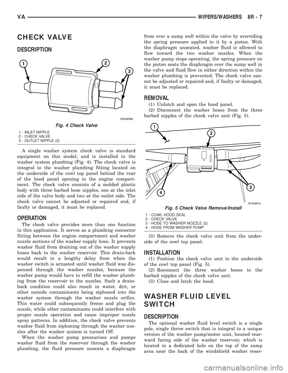
A single washer system check valve is standard
equipment on this model, and is installed in the
washer system plumbing (Fig. 4). The check valve is
integral to the washer plumbing fitting located on
the underside of the cowl top panel behind the rear
of the hood panel opening in the engine compart-
ment. The check valve consists of a molded plastic
body with three barbed hose nipples, one at the inlet
side of the valve body and two at the outlet side. The
check valve cannot be adjusted or repaired and, if
faulty or damaged, it must be replaced.
OPERATION
The check valve provides more than one function
in this application. It serves as a plumbing connector
fitting between the engine compartment and washer
nozzle sections of the washer supply hose. It prevents
washer fluid from draining out of the washer supply
hoses back to the washer reservoir. This drain-back
would result in a lengthy delay from when the
washer switch is actuated until washer fluid was dis-
pensed through the washer nozzles, because the
washer pump would have to refill the washer plumb-
ing from the reservoir to the nozzles. Such a drain-
back condition could also result in water, dirt, or
other outside contaminants being siphoned into the
washer system through the washer nozzle orifice.
This water could subsequently freeze and plug the
nozzle, while other contaminants could interfere with
proper nozzle operation and cause improper nozzle
spray patterns. In addition, the check valve prevents
washer fluid from siphoning through the washer noz-
zles after the washer system is turned Off.
When the washer pump pressurizes and pumps
washer fluid from the reservoir through the washer
plumbing, the fluid pressure unseats a diaphragmfrom over a sump well within the valve by overriding
the spring pressure applied to it by a piston. With
the diaphragm unseated, washer fluid is allowed to
flow toward the two washer nozzles. When the
washer pump stops operating, the spring pressure on
the piston seats the diaphragm over the sump well in
the valve and fluid flow in either direction within the
washer plumbing is prevented. The check valve can-
not be adjusted or repaired and, if faulty or damaged,
it must be replaced.
REMOVAL
(1) Unlatch and open the hood panel.
(2) Disconnect the washer hoses from the three
barbed nipples of the check valve unit (Fig. 5).
(3) Remove the check valve unit from the under-
side of the cowl top panel.
INSTALLATION
(1) Position the check valve unit to the underside
of the cowl top panel (Fig. 5).
(2) Reconnect the three washer hoses to the
barbed nipples of the check valve unit.
(3) Close and latch the hood.
WASHER FLUID LEVEL
SWITCH
DESCRIPTION
The optional washer fluid level switch is a single
pole, single throw switch that is integral to a unique
version of the washer pump/motor unit, located rear-
ward facing side of the washer reservoir, which is
located in a dedicated hole on the top of the sump
area near the back of the windshield washer reser-
Fig. 4 Check Valve
1 - INLET NIPPLE
2 - CHECK VALVE
3 - OUTLET NIPPLE (2)
Fig. 5 Check Valve Remove/Install
1 - COWL HOOD SEAL
2 - CHECK VALVE
3 - HOSE TO WASHER NOZZLE (2)
4 - HOSE FROM WASHER PUMP
VAWIPERS/WASHERS 8R - 7
Page 1036 of 1232

STANDARD PROCEDURE - DUAL REAR WHEEL
INSTALLATION
The tires on both wheels must be completely raised
off the ground when tightening the lug nuts. This
will ensure correct wheel centering and maximum
wheel clamping.
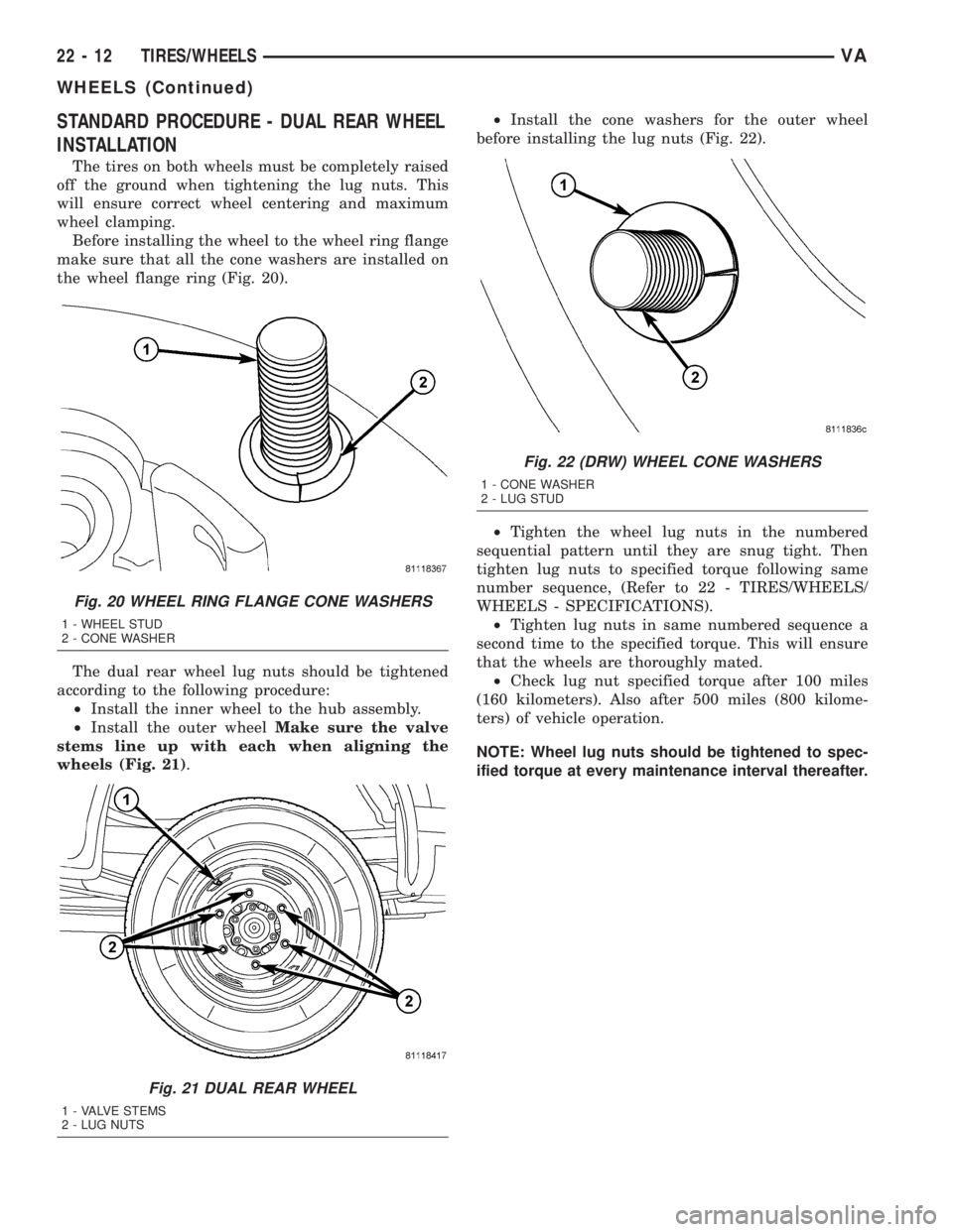
Before installing the wheel to the wheel ring flange
make sure that all the cone washers are installed on
the wheel flange ring (Fig. 20).
The dual rear wheel lug nuts should be tightened
according to the following procedure:
²Install the inner wheel to the hub assembly.
²Install the outer wheelMake sure the valve
stems line up with each when aligning the
wheels (Fig. 21).²Install the cone washers for the outer wheel
before installing the lug nuts (Fig. 22).
²Tighten the wheel lug nuts in the numbered
sequential pattern until they are snug tight. Then
tighten lug nuts to specified torque following same
number sequence, (Refer to 22 - TIRES/WHEELS/
WHEELS - SPECIFICATIONS).
²Tighten lug nuts in same numbered sequence a
second time to the specified torque. This will ensure
that the wheels are thoroughly mated.
²Check lug nut specified torque after 100 miles
(160 kilometers). Also after 500 miles (800 kilome-
ters) of vehicle operation.
NOTE: Wheel lug nuts should be tightened to spec-
ified torque at every maintenance interval thereafter.
Fig. 20 WHEEL RING FLANGE CONE WASHERS
1 - WHEEL STUD
2 - CONE WASHER
Fig. 21 DUAL REAR WHEEL
1 - VALVE STEMS
2 - LUG NUTS
Fig. 22 (DRW) WHEEL CONE WASHERS
1 - CONE WASHER
2 - LUG STUD
22 - 12 TIRES/WHEELSVA
WHEELS (Continued)
Page 1222 of 1232

PANEL CENTER BEZEL - REMOVAL,
INSTRUMENT.......................23-55
PANEL DUCTS - INSTALLATION,
INSTRUMENT.......................24-38
PANEL DUCTS - REMOVAL,
INSTRUMENT.......................24-37
PANEL REPAIR - STANDARD
PROCEDURE, PLASTIC BODY............23-3
PARK BRAKE, SPECIAL TOOLS...........5-23
PARK BRAKE SWITCH - INSTALLATION . . . 8L-20
PARK BRAKE SWITCH - REMOVAL.......8L-20
PARK LOCK CABLE - INSTALLATION.....21-126
PARK LOCK CABLE - REMOVAL........21-125
PARKING BRAKE CABLES -
ADJUSTMENT........................5-25
PARK/NEUTRAL CONTACT -
DESCRIPTION......................21-139
PARK/NEUTRAL CONTACT - OPERATION . 21-140
PARTS & LUBRICANT
RECOMMENDATIONS - STANDARD
PROCEDURE..........................0-5
PASSENGER AIRBAG - DESCRIPTION....8O-23
PASSENGER AIRBAG - INSTALLATION....8O-26
PASSENGER AIRBAG - OPERATION......8O-24
PASSENGER AIRBAG - REMOVAL........8O-24
PASSENGER AIRBAG BRACKET -
INSTALLATION......................8O-27
PASSENGER AIRBAG BRACKET -
REMOVAL..........................8O-27
PASSENGER HEATED SEAT SWITCH -
DESCRIPTION.........................8G-5
PASSENGER HEATED SEAT SWITCH -
DIAGNOSIS AND TESTING..............8G-5
PASSENGER HEATED SEAT SWITCH -
INSTALLATION.......................8G-5
PASSENGER HEATED SEAT SWITCH -
OPERATION..........................8G-5
PASSENGER HEATED SEAT SWITCH -
REMOVAL...........................8G-5
PATTERNS - DIAGNOSIS AND TESTING,
TIRE WEAR..........................22-8
PEDAL - INSTALLATION................5-19
PEDAL - REMOVAL....................5-18
PEDAL POSITION SENSOR -
DESCRIPTION, ACCELERATOR..........14-17
PERFORMANCE - DIAGNOSIS AND
TESTING, HEATER.....................24-4
PERFORMANCE TEST - DIAGNOSIS AND
TESTING, A/C........................24-3
PILLAR - INSTALLATION, REAR.........8L-29
PILLAR - REMOVAL, REAR.............8L-28
PINION SEAL - INSTALLATION...........3-22
PINION SEAL - REMOVAL...............3-22
PIPE - INSTALLATION, EXHAUST.........11-3
PIPE - REMOVAL, EXHAUST.............11-3
PISTON & CONNECTING ROD -
DESCRIPTION........................9-40
PISTON PROTRUSION - STANDARD
PROCEDURE, MEASURING..............9-42
PISTON RING FITTING - STANDARD
PROCEDURE.........................9-46
PISTONS - DESCRIPTION.............21-128
PISTONS - OPERATION...............21-128
PLANETARY GEARTRAIN - ASSEMBLY . . . 21-131
PLANETARY GEARTRAIN - DESCRIPTION . 21-130
PLANETARY GEARTRAIN -
DISASSEMBLY......................21-131
PLANETARY GEARTRAIN - OPERATION . . 21-130
PLASTIC BODY PANEL REPAIR -
STANDARD PROCEDURE................23-3
PLATE BRACKET - INSTALLATION,
LICENSE...........................23-47
PLATE BRACKET - REMOVAL, LICENSE . . . 23-47
PLATE LAMP BULB - INSTALLATION,
LICENSE...........................8L-18
PLATE LAMP BULB - REMOVAL,
LICENSE...........................8L-17
PLATE LAMP UNIT - INSTALLATION,
LICENSE...........................8L-18
PLATE LAMP UNIT - REMOVAL, LICENSE . . 8L-18
PLATES - INSTALLATION, SPRING
CLAMP..............................2-8
PLATES - INSTALLATION, SPRING STOP....2-9
PLATES - REMOVAL, SPRING CLAMP
......2-8
PLATES - REMOVAL, SPRING STOP
........2-9
PLUG - INSTALLATION, GLOW
............8I-1
PLUG - REMOVAL, GLOW
...............8I-1
PLUG RELAY - DESCRIPTION, GLOW
......8I-2PLUG RELAY - OPERATION, GLOW........8I-2
PLUG RELAYS - DIAGNOSIS AND
TESTING, GLOW.......................8I-2
PLUGS - STANDARD PROCEDURE,
REPLACING ENGINE CORE AND OIL
GALLERY............................9-34
PLUMBING - CLEANING, CHARGE AIR
COOLER.............................11-5
PLUMBING - DESCRIPTION, CHARGE
AIR COOLER.........................11-4
PLUMBING - INSPECTION, CHARGE AIR
COOLER.............................11-5
PLUMBING - INSTALLATION, CHARGE
AIR COOLER.........................11-5
PLUMBING - OPERATION, CHARGE AIR
COOLER.............................11-4
PLUMBING - REMOVAL, CHARGE AIR
COOLER.............................11-5
PLUMBING - WARNING................24-44
PLY TIRES - DESCRIPTION, RADIAL.......22-6
POLISH - DESCRIPTION, FINESSE
SANDING/BUFFING...................23-75
POSITION - STANDARD PROCEDURE,
CHECKING CAMSHAFT.................9-27
POSITION LAMP BULB - INSTALLATION,
FRONT.............................8L-14
POSITION LAMP BULB - REMOVAL,
FRONT.............................8L-14
POSITION SENSOR - DESCRIPTION,
ACCELERATOR PEDAL.................14-17
POSITION SENSOR - DESCRIPTION,
CAMSHAFT.........................14-19
POSITION SENSOR - DESCRIPTION,
CRANKSHAFT.......................14-20
POSITION SENSOR - INSTALLATION,
CAMSHAFT.........................14-19
POSITION SENSOR - INSTALLATION,
CRANKSHAFT.......................14-20
POSITION SENSOR - OPERATION,
CAMSHAFT.........................14-19
POSITION SENSOR - OPERATION,
CRANKSHAFT.......................14-20
POSITION SENSOR - REMOVAL,
CAMSHAFT.........................14-19
POSITION SENSOR - REMOVAL,
CRANKSHAFT.......................14-20
POTENTIAL - STANDARD PROCEDURE,
TESTING OF VOLTAGE..............8W-01-7
POWER - INSTALLATION, WINDOW
REGULATOR........................23-21
POWER - REMOVAL, WINDOW
REGULATOR........................23-20
POWER BRAKE BOOSTER -
DESCRIPTION........................5-19
POWER BRAKE BOOSTER -
INSTALLATION........................5-19
POWER BRAKE BOOSTER - OPERATION . . . 5-19
POWER BRAKE BOOSTER - REMOVAL.....5-19
POWER DISTRIBUTION - DESCRIPTION . 8W-97-1
POWER DISTRIBUTION - OPERATION . . 8W-97-1
POWER DISTRIBUTION CENTER -
DESCRIPTION.....................8W-97-3
POWER DISTRIBUTION CENTER -
OPERATION.......................8W-97-3
POWER LOCKS - DESCRIPTION..........8N-1
POWER MIRROR SWITCH - DIAGNOSIS
AND TESTING........................8N-3
POWER MIRROR SWITCH -
INSTALLATION.......................8N-4
POWER MIRROR SWITCH - REMOVAL....8N-3
POWER MIRRORS - DESCRIPTION.......8N-3
POWER OUTLET - DESCRIPTION......8W-97-3
POWER OUTLET - DIAGNOSIS AND
TESTING.........................8W-97-4
POWER OUTLET - INSTALLATION.....8W-97-4
POWER OUTLET - OPERATION........8W-97-4
POWER OUTLET - REMOVAL.........8W-97-4
POWER STEERING FLUID -
DESCRIPTION
.........................0-3
POWER STEERING PUMP - INITIAL
OPERATION - STANDARD PROCEDURE
. . . 19-12
POWER STEERING PUMP FILL AND
BLEED PROCEDURE, STANDARD
PROCEDURE
........................19-14
POWER STEERING SYSTEM -
DIAGNOSIS AND TESTING
..............19-2
POWER STEERING SYSTEM -
STANDARD PROCEDURE, FLUSHING
.....19-13POWER WINDOW SWITCH - DIAGNOSIS
AND TESTING........................8N-5
POWER WINDOW SWITCH -
INSTALLATION.......................8N-6
POWER WINDOW SWITCH - REMOVAL....8N-6
POWER WINDOWS - DESCRIPTION.......8N-5
POWER WINDOWS - OPERATION.........8N-5
POWERING SEVERAL LOADS -
STANDARD PROCEDURE, TESTING
FOR A SHORT TO GROUND ON FUSES . 8W-01-8
PRE-ALIGNMENT INSPECTION -
DIAGNOSIS AND TESTING..............2-17
PRECAUTIONS AND WARNINGS,
WARNING - SAFETY...................23-1
PRECAUTIONS, CAUTION -
REFRIGERANT HOSES/LINES/TUBES......24-45
PRECAUTIONS, WARNING -
WINDSHIELD SAFETY.................23-82
PRELIMINARY - DIAGNOSIS AND
TESTING...........................21-23
PRELIMINARY CHECKS - DIAGNOSIS
AND TESTING.........................7-1
PRESSURE - WARNING, HIGH FUEL
SYSTEM............................14-1
PRESSURE BLEEDING - STANDARD
PROCEDURE..........................5-5
PRESSURE CAP - DESCRIPTION,
RADIATOR...........................7-18
PRESSURE CAP - DIAGNOSIS AND
TESTING, RADIATOR...................7-19
PRESSURE CAP - OPERATION,
RADIATOR...........................7-18
PRESSURE FOR HIGH SPEEDS -
DESCRIPTION, TIRE...................22-6
PRESSURE FUEL LINES - DIAGNOSIS
AND TESTING, HIGH...................14-1
PRESSURE FUEL PUMP TEST -
STANDARD PROCEDURE, LOW...........14-3
PRESSURE FUEL SHUTOFF SOL -
DESCRIPTION, HI....................14-16
PRESSURE FUEL SHUTOFF SOL -
OPERATION, HI......................14-16
PRESSURE GAUGES - DIAGNOSIS AND
TESTING............................22-8
PRESSURE HOSE - INSTALLATION.......19-15
PRESSURE HOSE - REMOVAL..........19-15
PRESSURE LINES - INSTALLATION, HIGH . . 14-7
PRESSURE LINES - REMOVAL, HIGH......14-6
PRESSURE LOSS - STANDARD
PROCEDURE, DETERMINING
CYLINDER............................9-4
PRESSURE PUMP - DESCRIPTION, HIGH . . . 14-7
PRESSURE PUMP - DESCRIPTION, LOW . . . 14-7
PRESSURE PUMP - INSTALLATION,
HIGH..............................14-10
PRESSURE PUMP - INSTALLATION, LOW . 14-11
PRESSURE PUMP - OPERATION, LOW.....14-8
PRESSURE PUMP - REMOVAL, HIGH......14-8
PRESSURE PUMP - REMOVAL, LOW......14-9
PRESSURE SENSOR - DESCRIPTION,
BOOST.............................14-17
PRESSURE SENSOR - DIAGNOSIS AND
TESTING, BOOST.....................14-18
PRESSURE SENSOR - INSTALLATION,
BOOST.............................14-18
PRESSURE SENSOR - OPERATION,
BOOST.............................14-18
PRESSURE SENSOR - REMOVAL, BOOST . . 14-18
PRESSURE SOLENOID - DESCRIPTION,
FUEL..............................14-27
PRESSURE SOLENOID - INSTALLATION,
FUEL..............................14-28
PRESSURE SOLENOID - OPERATION,
FUEL..............................14-27
PRESSURE SOLENOID - REMOVAL, FUEL . 14-28
PRESSURE TRANSDUCER -
DESCRIPTION, A/C...................24-13
PRESSURE TRANSDUCER - DIAGNOSIS
AND TESTING, A/C...................24-13
PRESSURE TRANSDUCER -
INSTALLATION, A/C
...................24-14
PRESSURE TRANSDUCER - OPERATION,
A/C
................................24-13
PRESSURE TRANSDUCER - REMOVAL,
A/C
................................24-14
PRESSURES - DESCRIPTION, TIRE
INFLATION
...........................22-7
PROP ROD - INSTALLATION
............23-52
12 INDEXVA
Description Group-Page Description Group-Page Description Group-Page