2005 MERCEDES-BENZ SPRINTER clock
[x] Cancel search: clockPage 18 of 1232
MAINTENANCE - WITH ASSYST MAINTENANCE
COMPUTER
ASSYST provides information on the best possible
timing for maintenance work.
NOTE: The engine manufacturer strongly recom-
mends the use of synthetic engine oils, such as
TMobil 1 SAE 0W-40.
When the next maintenance service is due, this
will be indicated in the multi-function display with
the wrench icon symbol displayed in km/miles or
days.
²One wrench icon showing indicates Oil Service
is necessary.
²Two wrench icons showing indicates Mainte-
nance Service is necessary ± displayed in km/miles or
days.
If the display shows the number of days, a clock
symbol will also appear in the multi-function display.
You should have the maintenance performed
within the stated period/distance.
The service indicator should be reset after an oil
service and/or maintenance service has been per-
formed.
REGULAR CHECK-UPS
To maintain the safe operation of the vehicle, it is
recommended that the following tasks be performed
on a regular basis (i.e. weekly or whenever the vehi-
cle is refueled). Check:
²Engine oil level
²Brake system, clutch mechanism ± fluid level
²Battery ± acid level
²Windshield washer system and headlamp clean-
ing system ± fluid level
²Mechanical assemblies (e. g. engine, transmis-
sion, etc.) ± check for leaks
²Condition of tires and tires pressures
²All exterior lights
SPECIAL MAINTENANCE REQUIREMENTS
If bodies built by manufacturers other than
DaimlerChrysler Corporation are fitted to the vehi-
cle, the maintenance requirements and lubrication
intervals specified by the body manufacturer must be
adhered to, in addition to all standard maintenance
requirements.
Brake Fluid
Only use brake fluids approved by the manufac-
turer (DOT 4 plus).
Coolant
Corrosion inhibitor/antifreeze concentration in the
coolant should be checked before the onset of winter
(once year in countries with high prevailing temper-
atures).Replace the coolant every five years or 100,000
miles.
Dust Filter for Heating/Ventilation Replace-
ment
The dust filter and the tailgate interior filter are to
be renewed during routine maintenance service. If
operating conditions are dusty, these filters should be
renewed more frequently.
ENGINE OIL CHANGE AND FILTER REPLACEMENT
At the minimum, change the engine oil and oil fil-
ter once a year ± even if the vehicle mileage per year
is extremely low. For standard oil service schedules
refer to the chapter oil service and maintenance ser-
vice.
Once a Year
Select the viscosity of the engine oil (SAE classes)
according to the outside air temperature.
Only use engine oil approved by DaimlerChrysler
Corporation if following the ASSYST system guide-
lines.
If the fuel used has a sulphur content exceeding
0.05% by weight, the service intervals should be split
in half.
SCOPE OF WORK FOR MAINTENANCE SERVICE
Oil Service
²Engine:
Oil change and filter replacement
Check fluid levels of the following system,
refill as necessary.
²If fluid is lost, trace and eliminate cause ± as a
separate order.
²Power-assisted steering
Lubrication work:
²Trailer tow hitch (original equipment)
Maintenance
²ASSYST maintenance computer reset
Function check
²Signalling system, warning and indicator lamps
²Headlamps, exterior lighting
²Windshield wipers, windshield washer system
Check for leaks and damage.
²Check for abrasion points and ensure that lines
are correctly routed!
²All lines and hoses, sensor cables
²Rubber boots on front axle drive shafts, rubber
boots on front axle suspension ball joints, shock
absorbers
Check fluid levels for the following systems,
correct as necessary.
NOTE: Should there be a loss of fluid which cannot
be explained by regular use, trace and eliminate the
cause.
0 - 8 LUBRICATION & MAINTENANCEVA
MAINTENANCE SCHEDULES (Continued)
Page 89 of 1232
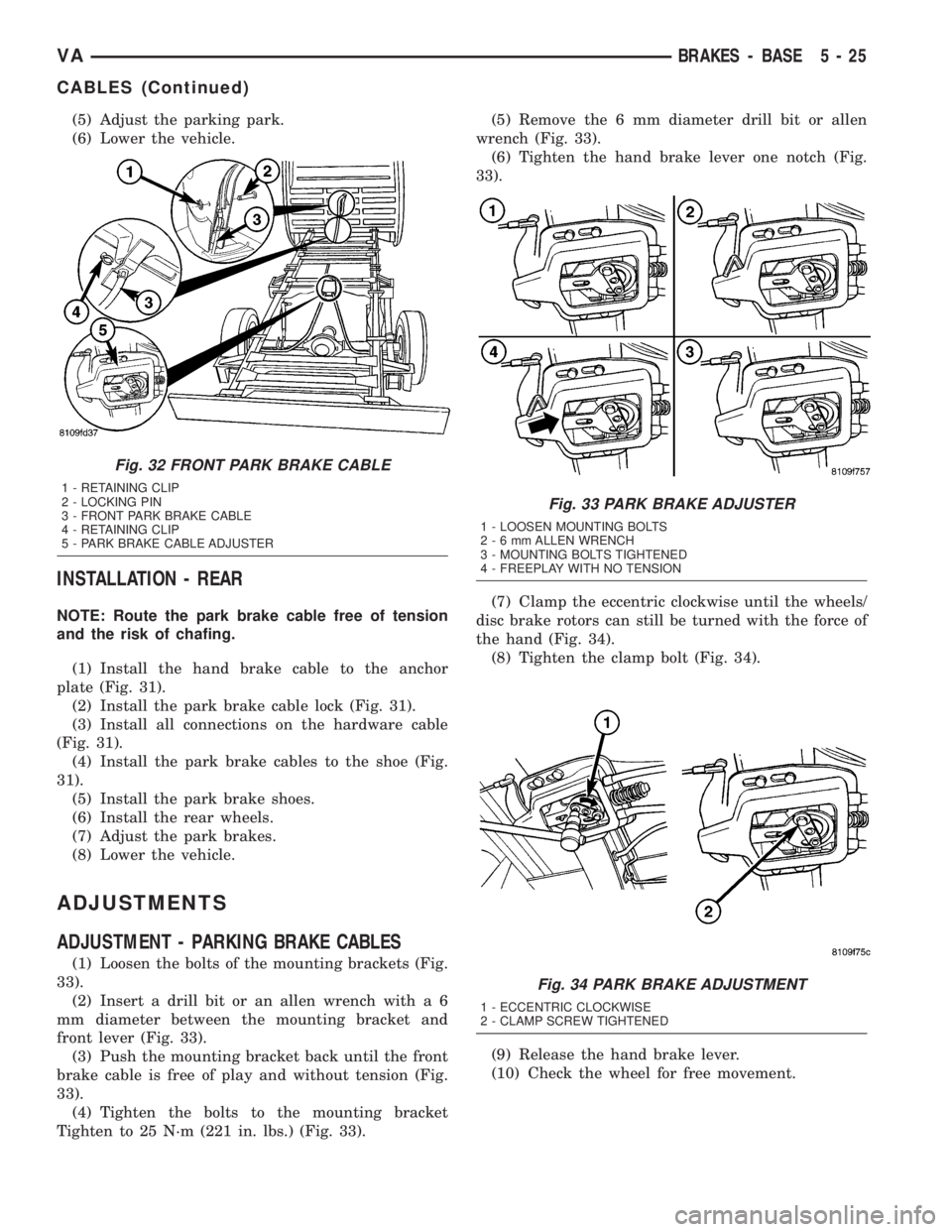
(5) Adjust the parking park.
(6) Lower the vehicle.
INSTALLATION - REAR
NOTE: Route the park brake cable free of tension
and the risk of chafing.
(1) Install the hand brake cable to the anchor
plate (Fig. 31).
(2) Install the park brake cable lock (Fig. 31).
(3) Install all connections on the hardware cable
(Fig. 31).
(4) Install the park brake cables to the shoe (Fig.
31).
(5) Install the park brake shoes.
(6) Install the rear wheels.
(7) Adjust the park brakes.
(8) Lower the vehicle.
ADJUSTMENTS
ADJUSTMENT - PARKING BRAKE CABLES
(1) Loosen the bolts of the mounting brackets (Fig.
33).
(2) Insert a drill bit or an allen wrench with a 6
mm diameter between the mounting bracket and
front lever (Fig. 33).
(3) Push the mounting bracket back until the front
brake cable is free of play and without tension (Fig.
33).
(4) Tighten the bolts to the mounting bracket
Tighten to 25 N´m (221 in. lbs.) (Fig. 33).(5) Remove the 6 mm diameter drill bit or allen
wrench (Fig. 33).
(6) Tighten the hand brake lever one notch (Fig.
33).
(7) Clamp the eccentric clockwise until the wheels/
disc brake rotors can still be turned with the force of
the hand (Fig. 34).
(8) Tighten the clamp bolt (Fig. 34).
(9) Release the hand brake lever.
(10) Check the wheel for free movement.
Fig. 32 FRONT PARK BRAKE CABLE
1 - RETAINING CLIP
2 - LOCKING PIN
3 - FRONT PARK BRAKE CABLE
4 - RETAINING CLIP
5 - PARK BRAKE CABLE ADJUSTER
Fig. 33 PARK BRAKE ADJUSTER
1 - LOOSEN MOUNTING BOLTS
2-6mmALLEN WRENCH
3 - MOUNTING BOLTS TIGHTENED
4 - FREEPLAY WITH NO TENSION
Fig. 34 PARK BRAKE ADJUSTMENT
1 - ECCENTRIC CLOCKWISE
2 - CLAMP SCREW TIGHTENED
VABRAKES - BASE 5 - 25
CABLES (Continued)
Page 104 of 1232
REMOVAL
CAUTION: Do not attempt to check belt tension with
a belt tension gauge on vehicles equipped with an
automatic belt tensioner.
NOTE: The belt routing schematics are published
from the latest information available at the time of
publication. If anything differs between these sche-
matics and the Belt Routing Label, use the sche-
matics on Belt Routing Label.This label is located in
the engine compartment.
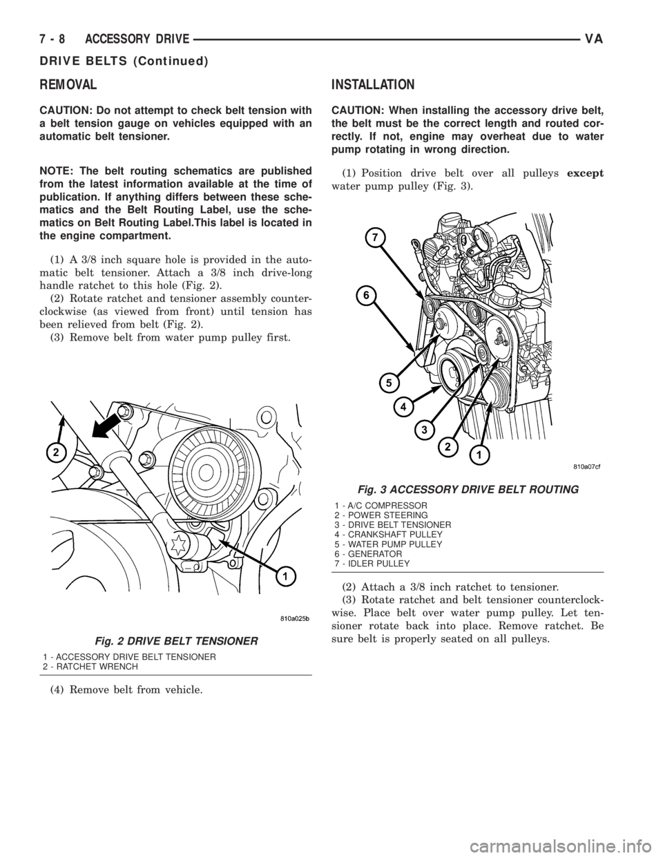
(1) A 3/8 inch square hole is provided in the auto-
matic belt tensioner. Attach a 3/8 inch drive-long
handle ratchet to this hole (Fig. 2).
(2) Rotate ratchet and tensioner assembly counter-
clockwise (as viewed from front) until tension has
been relieved from belt (Fig. 2).
(3) Remove belt from water pump pulley first.
(4) Remove belt from vehicle.
INSTALLATION
CAUTION: When installing the accessory drive belt,
the belt must be the correct length and routed cor-
rectly. If not, engine may overheat due to water
pump rotating in wrong direction.
(1) Position drive belt over all pulleysexcept
water pump pulley (Fig. 3).
(2) Attach a 3/8 inch ratchet to tensioner.
(3) Rotate ratchet and belt tensioner counterclock-
wise. Place belt over water pump pulley. Let ten-
sioner rotate back into place. Remove ratchet. Be
sure belt is properly seated on all pulleys.
Fig. 2 DRIVE BELT TENSIONER
1 - ACCESSORY DRIVE BELT TENSIONER
2 - RATCHET WRENCH
Fig. 3 ACCESSORY DRIVE BELT ROUTING
1 - A/C COMPRESSOR
2 - POWER STEERING
3 - DRIVE BELT TENSIONER
4 - CRANKSHAFT PULLEY
5 - WATER PUMP PULLEY
6 - GENERATOR
7 - IDLER PULLEY
7 - 8 ACCESSORY DRIVEVA
DRIVE BELTS (Continued)
Page 109 of 1232
COOLANT LEVEL SENSOR
REMOVAL
WARNING: RISK OF INJURY TO SKIN AND EYES
DUE TO SCALDING FROM HOT COOLANT. DO NOT
OPEN THE COOLING SYSTEM UNLESS THE TEM-
PERATURE IS BELOW 194ÉF (90ÉC). WEAR PRO-
TECTIVE CLOTHING AND EYE WEAR. RISK OF
POISONING IF COOLANT IS SWALLOWED. STORE
COOLANT IN PROPER AND APPROPRIATELY
MARKED CONTAINERS.
NOTE: Drain coolant from radiator drain plug only.
(1) Drain coolant until the coolant reservoir is
emptied.
(2) Disconnect the wiring harness electrical con-
nector.
(3) Turn the level sensor 90 degrees clockwises, lift
up and out of the container.
INSTALLATION
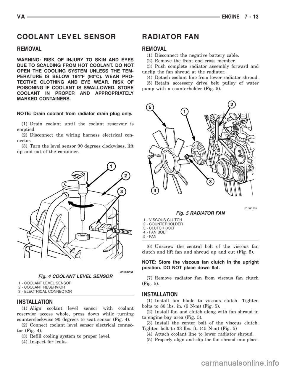
(1) Align coolant level sensor with coolant
reservior access whole, press down while turning
counterclockwise 90 degrees to seat sensor (Fig. 4).
(2) Connect coolant level sensor electrical connec-
tor (Fig. 4).
(3) Refill cooling system to proper level.
(4) Inspect for leaks.
RADIATOR FAN
REMOVAL
(1) Disconnect the negative battery cable.
(2) Remove the front end cross member.
(3) Push complete radiator assembly forward and
unclip the fan shroud at the radiator.
(4) Detach coolant line from lower radiator shroud.
(5) Retain accessory drive belt pulley of water
pump with a counterholder (Fig. 5).
(6) Unscrew the central bolt of the viscous fan
clutch and lift fan and shroud up and out (Fig. 5).
NOTE: Store the viscous fan clutch in the upright
position. DO NOT place down flat.
(7) Remove radiator fan from viscous fan clutch
(Fig. 5).
INSTALLATION
(1) Install fan blade to viscous clutch. Tighten
bolts to 80 lbs. in. (9 N´m) (Fig. 5).
(2) Install fan and clutch along with fan shroud in
to engine bay area (Fig. 5).
(3) Install the center bolt of the viscous clutch.
Tighten bolt to 33 lbs. ft. (45 N´m) (Fig. 5)
(4) Attach coolant line to lower radiator shroud.
(5)
Properly align and clip the fan shroud into place.
Fig. 4 COOLANT LEVEL SENSOR
1 - COOLANT LEVEL SENSOR
2 - COOLANT RESERVIOR
3 - ELECTRICAL CONNECTOR
Fig. 5 RADIATOR FAN
1 - VISCOUS CLUTCH
2 - COUNTERHOLDER
3 - CLUTCH BOLT
4 - FAN BOLT
5-FAN
VAENGINE 7 - 13
Page 138 of 1232
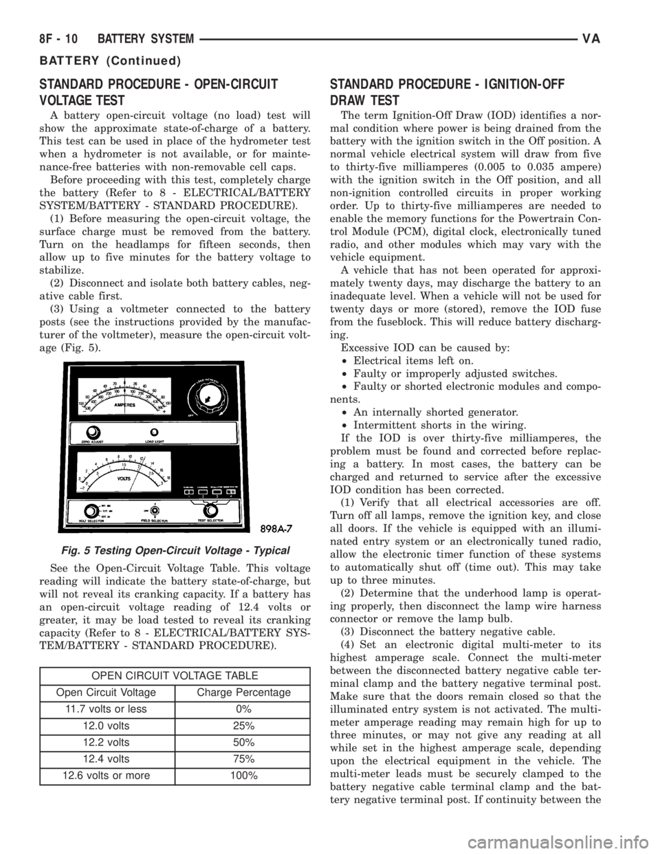
STANDARD PROCEDURE - OPEN-CIRCUIT
VOLTAGE TEST
A battery open-circuit voltage (no load) test will
show the approximate state-of-charge of a battery.
This test can be used in place of the hydrometer test
when a hydrometer is not available, or for mainte-
nance-free batteries with non-removable cell caps.
Before proceeding with this test, completely charge
the battery (Refer to 8 - ELECTRICAL/BATTERY
SYSTEM/BATTERY - STANDARD PROCEDURE).
(1) Before measuring the open-circuit voltage, the
surface charge must be removed from the battery.
Turn on the headlamps for fifteen seconds, then
allow up to five minutes for the battery voltage to
stabilize.
(2) Disconnect and isolate both battery cables, neg-
ative cable first.
(3) Using a voltmeter connected to the battery
posts (see the instructions provided by the manufac-
turer of the voltmeter), measure the open-circuit volt-
age (Fig. 5).
See the Open-Circuit Voltage Table. This voltage
reading will indicate the battery state-of-charge, but
will not reveal its cranking capacity. If a battery has
an open-circuit voltage reading of 12.4 volts or
greater, it may be load tested to reveal its cranking
capacity (Refer to 8 - ELECTRICAL/BATTERY SYS-
TEM/BATTERY - STANDARD PROCEDURE).
OPEN CIRCUIT VOLTAGE TABLE
Open Circuit Voltage Charge Percentage
11.7 volts or less 0%
12.0 volts 25%
12.2 volts 50%
12.4 volts 75%
12.6 volts or more 100%
STANDARD PROCEDURE - IGNITION-OFF
DRAW TEST
The term Ignition-Off Draw (IOD) identifies a nor-
mal condition where power is being drained from the
battery with the ignition switch in the Off position. A
normal vehicle electrical system will draw from five
to thirty-five milliamperes (0.005 to 0.035 ampere)
with the ignition switch in the Off position, and all
non-ignition controlled circuits in proper working
order. Up to thirty-five milliamperes are needed to
enable the memory functions for the Powertrain Con-
trol Module (PCM), digital clock, electronically tuned
radio, and other modules which may vary with the
vehicle equipment.
A vehicle that has not been operated for approxi-
mately twenty days, may discharge the battery to an
inadequate level. When a vehicle will not be used for
twenty days or more (stored), remove the IOD fuse
from the fuseblock. This will reduce battery discharg-
ing.
Excessive IOD can be caused by:
²Electrical items left on.
²Faulty or improperly adjusted switches.
²Faulty or shorted electronic modules and compo-
nents.
²An internally shorted generator.
²Intermittent shorts in the wiring.
If the IOD is over thirty-five milliamperes, the
problem must be found and corrected before replac-
ing a battery. In most cases, the battery can be
charged and returned to service after the excessive
IOD condition has been corrected.
(1) Verify that all electrical accessories are off.
Turn off all lamps, remove the ignition key, and close
all doors. If the vehicle is equipped with an illumi-
nated entry system or an electronically tuned radio,
allow the electronic timer function of these systems
to automatically shut off (time out). This may take
up to three minutes.
(2) Determine that the underhood lamp is operat-
ing properly, then disconnect the lamp wire harness
connector or remove the lamp bulb.
(3) Disconnect the battery negative cable.
(4) Set an electronic digital multi-meter to its
highest amperage scale. Connect the multi-meter
between the disconnected battery negative cable ter-
minal clamp and the battery negative terminal post.
Make sure that the doors remain closed so that the
illuminated entry system is not activated. The multi-
meter amperage reading may remain high for up to
three minutes, or may not give any reading at all
while set in the highest amperage scale, depending
upon the electrical equipment in the vehicle. The
multi-meter leads must be securely clamped to the
battery negative cable terminal clamp and the bat-
tery negative terminal post. If continuity between the
Fig. 5 Testing Open-Circuit Voltage - Typical
8F - 10 BATTERY SYSTEMVA
BATTERY (Continued)
Page 149 of 1232
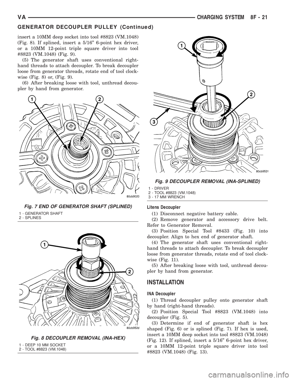
insert a 10MM deep socket into tool #8823 (VM.1048)
(Fig. 8). If splined, insert a 5/16º 6-point hex driver,
or a 10MM 12-point triple square driver into tool
#8823 (VM.1048) (Fig. 9).
(5) The generator shaft uses conventional right-
hand threads to attach decoupler. To break decoupler
loose from generator threads, rotate end of tool clock-
wise (Fig. 8) or, (Fig. 9).
(6) After breaking loose with tool, unthread decou-
pler by hand from generator.
Litens Decoupler
(1) Disconnect negative battery cable.
(2) Remove generator and accessory drive belt.
Refer to Generator Removal.
(3) Position Special Tool #8433 (Fig. 10) into
decoupler. Align to hex end of generator shaft.
(4) The generator shaft uses conventional right-
hand threads to attach decoupler. To break decoupler
loose from generator threads, rotate end of tool clock-
wise (Fig. 11).
(5) After breaking loose with tool, unthread decou-
pler by hand from generator.
INSTALLATION
INA Decoupler
(1) Thread decoupler pulley onto generator shaft
by hand (right-hand threads).
(2) Position Special Tool #8823 (VM.1048) into
decoupler (Fig. 5).
(3) Determine if end of generator shaft is hex
shaped (Fig. 6) or is splined (Fig. 7). If hex is used,
insert a 10MM deep socket into tool #8823 (VM.1048)
(Fig. 12). If splined, insert a 5/16º 6-point hex driver,
or a 10MM 12-point triple square driver into tool
#8823 (VM.1048) (Fig. 13).
Fig. 7 END OF GENERATOR SHAFT (SPLINED)
1 - GENERATOR SHAFT
2 - SPLINES
Fig. 8 DECOUPLER REMOVAL (INA-HEX)
1 - DEEP 10 MM SOCKET
2 - TOOL #8823 (VM.1048)
Fig. 9 DECOUPLER REMOVAL (INA-SPLINED)
1 - DRIVER
2 - TOOL #8823 (VM.1048)
3 - 17 MM WRENCH
VACHARGING SYSTEM 8F - 21
GENERATOR DECOUPLER PULLEY (Continued)
Page 150 of 1232
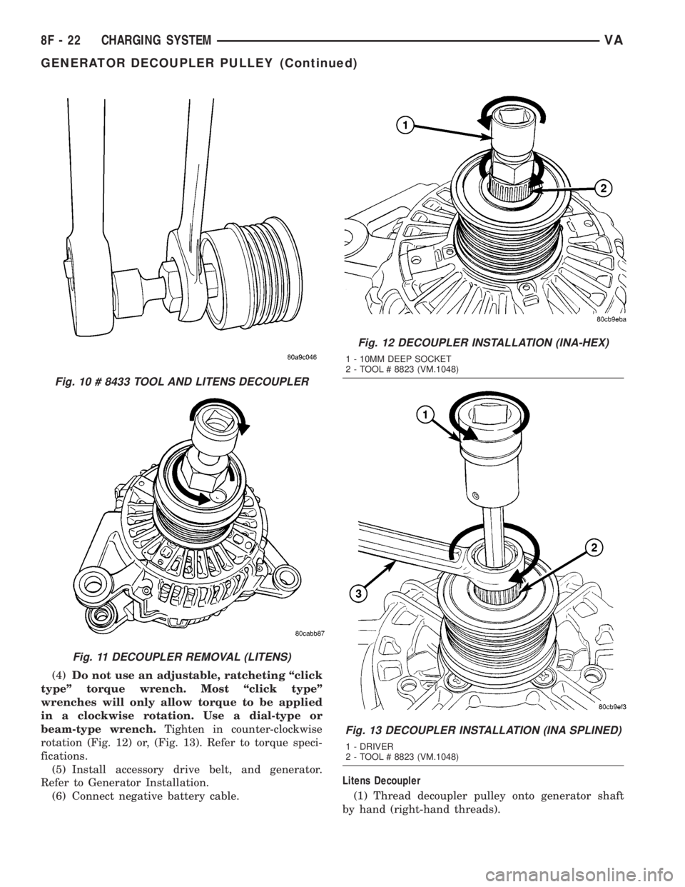
(4)Do not use an adjustable, ratcheting ªclick
typeº torque wrench. Most ªclick typeº
wrenches will only allow torque to be applied
in a clockwise rotation. Use a dial-type or
beam-type wrench.Tighten in counter-clockwise
rotation (Fig. 12) or, (Fig. 13). Refer to torque speci-
fications.
(5) Install accessory drive belt, and generator.
Refer to Generator Installation.
(6) Connect negative battery cable.Litens Decoupler
(1) Thread decoupler pulley onto generator shaft
by hand (right-hand threads).
Fig. 10 # 8433 TOOL AND LITENS DECOUPLER
Fig. 11 DECOUPLER REMOVAL (LITENS)
Fig. 12 DECOUPLER INSTALLATION (INA-HEX)
1 - 10MM DEEP SOCKET
2 - TOOL # 8823 (VM.1048)
Fig. 13 DECOUPLER INSTALLATION (INA SPLINED)
1 - DRIVER
2 - TOOL # 8823 (VM.1048)
8F - 22 CHARGING SYSTEMVA
GENERATOR DECOUPLER PULLEY (Continued)
Page 151 of 1232
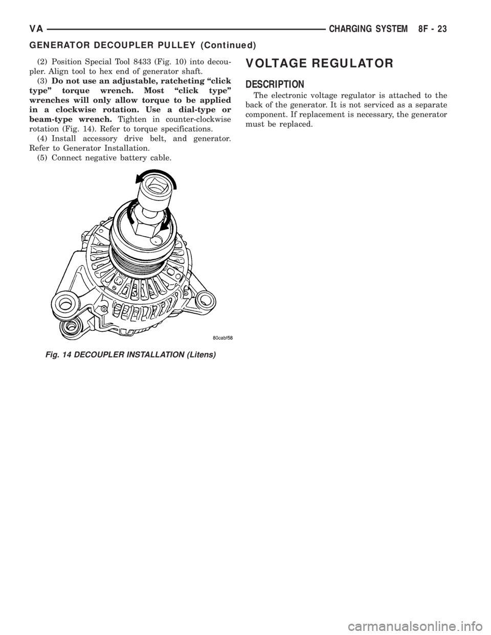
(2) Position Special Tool 8433 (Fig. 10) into decou-
pler. Align tool to hex end of generator shaft.
(3)Do not use an adjustable, ratcheting ªclick
typeº torque wrench. Most ªclick typeº
wrenches will only allow torque to be applied
in a clockwise rotation. Use a dial-type or
beam-type wrench.Tighten in counter-clockwise
rotation (Fig. 14). Refer to torque specifications.
(4) Install accessory drive belt, and generator.
Refer to Generator Installation.
(5) Connect negative battery cable.VOLTAGE REGULATOR
DESCRIPTION
The electronic voltage regulator is attached to the
back of the generator. It is not serviced as a separate
component. If replacement is necessary, the generator
must be replaced.
Fig. 14 DECOUPLER INSTALLATION (Litens)
VACHARGING SYSTEM 8F - 23
GENERATOR DECOUPLER PULLEY (Continued)