2005 MERCEDES-BENZ SPRINTER warning
[x] Cancel search: warningPage 4 of 1232
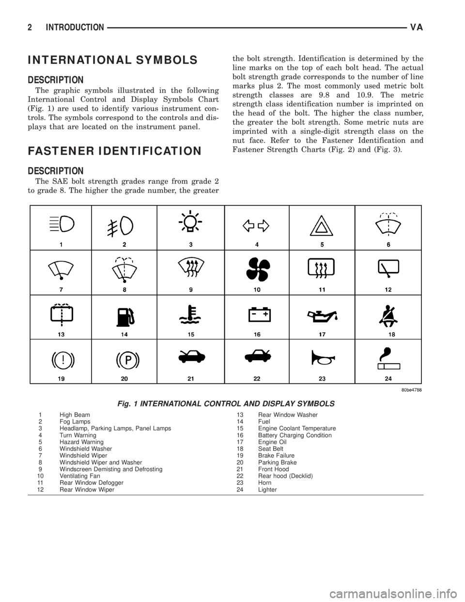
INTERNATIONAL SYMBOLS
DESCRIPTION
The graphic symbols illustrated in the following
International Control and Display Symbols Chart
(Fig. 1) are used to identify various instrument con-
trols. The symbols correspond to the controls and dis-
plays that are located on the instrument panel.
FASTENER IDENTIFICATION
DESCRIPTION
The SAE bolt strength grades range from grade 2
to grade 8. The higher the grade number, the greaterthe bolt strength. Identification is determined by the
line marks on the top of each bolt head. The actual
bolt strength grade corresponds to the number of line
marks plus 2. The most commonly used metric bolt
strength classes are 9.8 and 10.9. The metric
strength class identification number is imprinted on
the head of the bolt. The higher the class number,
the greater the bolt strength. Some metric nuts are
imprinted with a single-digit strength class on the
nut face. Refer to the Fastener Identification and
Fastener Strength Charts (Fig. 2) and (Fig. 3).
Fig. 1 INTERNATIONAL CONTROL AND DISPLAY SYMBOLS
1 High Beam 13 Rear Window Washer
2 Fog Lamps 14 Fuel
3 Headlamp, Parking Lamps, Panel Lamps 15 Engine Coolant Temperature
4 Turn Warning 16 Battery Charging Condition
5 Hazard Warning 17 Engine Oil
6 Windshield Washer 18 Seat Belt
7 Windshield Wiper 19 Brake Failure
8 Windshield Wiper and Washer 20 Parking Brake
9 Windscreen Demisting and Defrosting 21 Front Hood
10 Ventilating Fan 22 Rear hood (Decklid)
11 Rear Window Defogger 23 Horn
12 Rear Window Wiper 24 Lighter
2 INTRODUCTIONVA
Page 7 of 1232
FASTENER USAGE
DESCRIPTION - FASTENER USAGE
WARNING: USE OF AN INCORRECT FASTENER
MAY RESULT IN COMPONENT DAMAGE OR PER-
SONAL INJURY.
Fasteners and torque specifications references in
this Service Manual are identified in metric and SAE
format.
During any maintenance or repair procedures, it is
important to salvage all fasteners (nuts, bolts, etc.)
for reassembly. If the fastener is not salvageable, a
fastener of equivalent specification must be used.
THREADED HOLE REPAIR
DESCRIPTION - THREADED HOLE REPAIR
Most stripped threaded holes can be repaired using
a Helicoilt. Follow the vehicle or Helicoiltrecommen-
dations for application and repair procedures.
METRIC SYSTEM
DESCRIPTION
The metric system is based on quantities of one,
ten, one hundred, one thousand and one million.
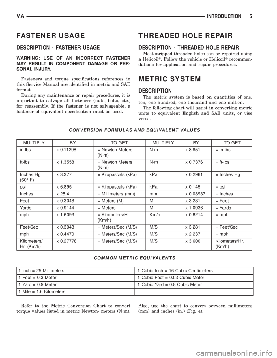
The following chart will assist in converting metric
units to equivalent English and SAE units, or vise
versa.
CONVERSION FORMULAS AND EQUIVALENT VALUES
MULTIPLY BY TO GET MULTIPLY BY TO GET
in-lbs x 0.11298 = Newton Meters
(N´m)N´m x 8.851 = in-lbs
ft-lbs x 1.3558 = Newton Meters
(N´m)N´m x 0.7376 = ft-lbs
Inches Hg
(60É F)x 3.377 = Kilopascals (kPa) kPa x 0.2961 = Inches Hg
psi x 6.895 = Kilopascals (kPa) kPa x 0.145 = psi
Inches x 25.4 = Millimeters (mm) mm x 0.03937 = Inches
Feet x 0.3048 = Meters (M) M x 3.281 = Feet
Yards x 0.9144 = Meters M x 1.0936 = Yards
mph x 1.6093 = Kilometers/Hr.
(Km/h)Km/h x 0.6214 = mph
Feet/Sec x 0.3048 = Meters/Sec (M/S) M/S x 3.281 = Feet/Sec
mph x 0.4470 = Meters/Sec (M/S) M/S x 2.237 = mph
Kilometers/
Hr. (Km/h)x 0.27778 = Meters/Sec (M/S) M/S x 3.600 Kilometers/Hr.
(Km/h)
COMMON METRIC EQUIVALENTS
1 inch = 25 Millimeters 1 Cubic Inch = 16 Cubic Centimeters
1 Foot = 0.3 Meter 1 Cubic Foot = 0.03 Cubic Meter
1 Yard = 0.9 Meter 1 Cubic Yard = 0.8 Cubic Meter
1 Mile = 1.6 Kilometers
Refer to the Metric Conversion Chart to convert
torque values listed in metric Newton- meters (N´m).Also, use the chart to convert between millimeters
(mm) and inches (in.) (Fig. 4).
VAINTRODUCTION 5
Page 11 of 1232
LUBRICATION & MAINTENANCE
TABLE OF CONTENTS
page page
FLUID TYPES
DESCRIPTION
DESCRIPTION - FUEL REQUIREMENTS -
DIESEL ENGINE.......................1
DESCRIPTION - ENGINE COOLANT........1
DESCRIPTION - HOAT COOLANT..........2
DESCRIPTION - AXLE...................3
DESCRIPTION - BRAKE FLUID............3
DESCRIPTION - POWER STEERING FLUID . . 3
DESCRIPTION - ENGINE OIL - DIESEL
ENGINES............................3
DESCRIPTION - AUTOMATIC
TRANSMISSION FLUID - NAG1............4
OPERATION - AUTOMATIC TRANSMISSION
FLUID...............................4
FLUID CAPACITIES
SPECIFICATIONS - FLUID CAPACITIES.......4FLUID FILL/CHECK LOCATIONS
INSPECTION - FLUID FILL/CHECK
LOCATIONS..........................4
PARTS & LUBRICANT RECOMMENDATION
STANDARD PROCEDURE - PARTS &
LUBRICANT RECOMMENDATIONS.........5
HOISTING
STANDARD PROCEDURE - HOISTING........5
JUMP STARTING
STANDARD PROCEDURE - JUMP STARTING . . 6
TOWING
STANDARD PROCEDURE - TOWING.........6
MAINTENANCE SCHEDULES
DESCRIPTION..........................7
INTERNATIONAL SYMBOLS
DESCRIPTION..........................9
FLUID TYPES
DESCRIPTION
DESCRIPTION - FUEL REQUIREMENTS -
DIESEL ENGINE
DESCRIPTION
WARNING: Do not use alcohol or gasoline as a fuel
blending agent. They can be unstable under certain
conditions and hazardous or explosive when mixed
with diesel fuel.
Use good quality diesel fuel from a reputable sup-
plier in your Dodge truck. For most year-round ser-
vice, number 2 diesel fuel meeting ASTM
specification D-975 will provide good performance. If
the vehicle is exposed to extreme cold (below 0ÉF/-
18ÉC), or is required to operate at colder-than-normal
conditions for prolonged periods, use climatized No. 2
diesel fuel or dilute the No. 2 diesel fuel with 50%
No. 1 diesel fuel. This will provide better protection
from fuel gelling or wax-plugging of the fuel filters.
Diesel fuel is seldom completely free of water. To
prevent fuel system trouble, including fuel line freez-
ing in winter, drain the accumulated water from the
fuel/water separator using the fuel/water separator
drain provided. If you buy good-quality fuel and fol-low the cold-weather advice above, fuel conditioners
should not be required in your vehicle. If available in
your area, a high cetane ªpremiumº diesel fuel may
offer improved cold starting and warm-up perfor-
mance.
DESCRIPTION - ENGINE COOLANT
ETHYLENE-GLYCOL MIXTURES
CAUTION: Richer antifreeze mixtures cannot be
measured with normal field equipment and can
cause problems associated with 100 percent ethyl-
ene-glycol.
The required ethylene-glycol (antifreeze) and water
mixture depends upon the climate and vehicle oper-
ating conditions. The recommended mixture of 50/50
ethylene-glycol and water will provide protection
against freezing to -37É C (-34É F). The antifreeze
concentrationmust alwaysbe a minimum of 44 per-
cent, year-round in all climates.If percentage is
lower than 44 percent, engine parts may be
eroded by cavitation, and cooling system com-
ponents may be severely damaged by corrosion.
Maximum protection against freezing is provided
with a 68 percent antifreeze concentration, which
prevents freezing down to -67.7É C (-90É F). A higher
percentage will freeze at a warmer temperature.
Also, a higher percentage of antifreeze can cause the
VALUBRICATION & MAINTENANCE 0 - 1
Page 12 of 1232
engine to overheat because the specific heat of anti-
freeze is lower than that of water.
Use of 100 percent ethylene-glycol will cause for-
mation of additive deposits in the system, as the cor-
rosion inhibitive additives in ethylene-glycol require
the presence of water to dissolve. The deposits act as
insulation, causing temperatures to rise. The
increased temperature can result in engine detona-
tion. In addition, 100 percent ethylene-glycol freezes
at -22É C (-8É F ).
PROPYLENE-GLYCOL MIXTURES
It's overall effective temperature range is smaller
than that of ethylene-glycol. The freeze point of 50/50
propylene-glycol and water is -32É C (-26É F), 10É C
higher than ethylene-glycol's freeze point. The boiling
point (protection against summer boil-over) of propy-
lene-glycol is 125É C (257ÉF)at96.5 kPa (14 psi),
compared to 128É C (263É F) for ethylene-glycol. Pro-
pylene glycol also has slightly poorer heat transfer
characteristics than ethylene glycol. This can
increase cylinder head temperatures under certain
conditions.
Propylene-glycol/ethylene-glycol mixtures can cause
the destabilization of various corrosion inhibitors,
causing damage to the various cooling system compo-
nents. Also, once ethylene-glycol and propylene-glycol
based coolants are mixed in the vehicle, conventional
methods of determining freeze point will not be accu-
rate. Both the refractive index and specific gravity
differ between ethylene glycol and propylene glycol.
DESCRIPTION - HOAT COOLANT
WARNING: ANTIFREEZE IS AN ETHYLENE-GLYCOL
BASE COOLANT AND IS HARMFUL IF SWAL-
LOWED OR INHALED. IF SWALLOWED, DRINK
TWO GLASSES OF WATER AND INDUCE VOMIT-
ING. IF INHALED, MOVE TO FRESH AIR AREA.
SEEK MEDICAL ATTENTION IMMEDIATELY. DO NOT
STORE IN OPEN OR UNMARKED CONTAINERS.
WASH SKIN AND CLOTHING THOROUGHLY AFTER
COMING IN CONTACT WITH ETHYLENE-GLYCOL.
KEEP OUT OF REACH OF CHILDREN. DISPOSE OF
GLYCOL BASE COOLANT PROPERLY, CONTACT
YOUR DEALER OR GOVERNMENT AGENCY FOR
LOCATION OF COLLECTION CENTER IN YOUR
AREA. DO NOT OPEN A COOLING SYSTEM WHEN
THE ENGINE IS AT OPERATING TEMPERATURE OR
HOT UNDER PRESSURE, PERSONAL INJURY CAN
RESULT. AVOID RADIATOR COOLING FAN WHEN
ENGINE COMPARTMENT RELATED SERVICE IS
PERFORMED, PERSONAL INJURY CAN RESULT.CAUTION: Use of Propylene-Glycol based coolants
is not recommended, as they provide less freeze
protection and less corrosion protection.
The cooling system is designed around the coolant.
The coolant must accept heat from engine metal, in
the cylinder head area near the exhaust valves and
engine block. Then coolant carries the heat to the
radiator where the tube/fin radiator can transfer the
heat to the air.
The use of aluminum cylinder blocks, cylinder
heads, and water pumps requires special corrosion
protection. MopartAntifreeze/Coolant, 5
Year/100,000 Mile Formula (MS-9769), or the equiva-
lent ethylene-glycol base coolant with organic corro-
sion inhibitors (called HOAT, for Hybrid Organic
Additive Technology) is recommended. This coolant
offers the best engine cooling without corrosion when
mixed with 50% ethylene-glycol and 50% distilled
water to obtain a freeze point of -37ÉC (-34ÉF). If it
loses color or becomes contaminated, drain, flush,
and replace with fresh properly mixed coolant solu-
tion.
CAUTION: MoparTAntifreeze/Coolant, 5
Year/100,000 Mile Formula (MS-9769) may not be
mixed with any other type of antifreeze. Mixing of
coolants other than specified (non-HOAT), may
result in engine damage that may not be covered
under the new vehicle warranty, and decreased cor-
rosion protection.
COOLANT PERFORMANCE
The required ethylene-glycol (antifreeze) and water
mixture depends upon climate and vehicle operating
conditions. The coolant performance of various mix-
tures follows:
Pure Water-Water can absorb more heat than a
mixture of water and ethylene-glycol. This is for pur-
pose of heat transfer only. Water also freezes at a
higher temperature and allows corrosion.
100 percent Ethylene-Glycol-The corrosion
inhibiting additives in ethylene-glycol need the pres-
ence of water to dissolve. Without water, additives
form deposits in system. These act as insulation
causing temperature to rise. The increased tempera-
ture can result in engine detonation. In addition, 100
percent ethylene-glycol freezes at -22ÉC (-8ÉF).
50/50 Ethylene-Glycol and Water-Is the recom-
mended mixture, it provides protection against freez-
ing to -37ÉC (-34ÉF). The antifreeze concentration
must alwaysbe a minimum of 44 percent, year-
round in all climates. If percentage is lower, engine
parts may be eroded by cavitation. Maximum protec-
tion against freezing is provided with a 68 percent
antifreeze concentration, which prevents freezing
0 - 2 LUBRICATION & MAINTENANCEVA
FLUID TYPES (Continued)
Page 15 of 1232
PARTS & LUBRICANT
RECOMMENDATION
STANDARD PROCEDURE - PARTS &
LUBRICANT RECOMMENDATIONS
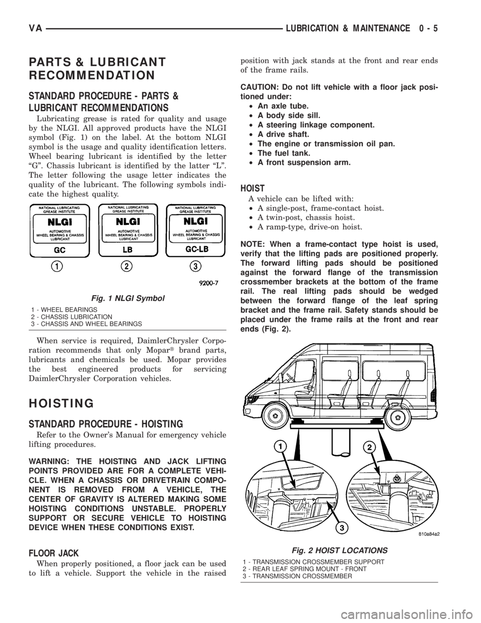
Lubricating grease is rated for quality and usage
by the NLGI. All approved products have the NLGI
symbol (Fig. 1) on the label. At the bottom NLGI
symbol is the usage and quality identification letters.
Wheel bearing lubricant is identified by the letter
ªGº. Chassis lubricant is identified by the latter ªLº.
The letter following the usage letter indicates the
quality of the lubricant. The following symbols indi-
cate the highest quality.
When service is required, DaimlerChrysler Corpo-
ration recommends that only Mopartbrand parts,
lubricants and chemicals be used. Mopar provides
the best engineered products for servicing
DaimlerChrysler Corporation vehicles.
HOISTING
STANDARD PROCEDURE - HOISTING
Refer to the Owner's Manual for emergency vehicle
lifting procedures.
WARNING: THE HOISTING AND JACK LIFTING
POINTS PROVIDED ARE FOR A COMPLETE VEHI-
CLE. WHEN A CHASSIS OR DRIVETRAIN COMPO-
NENT IS REMOVED FROM A VEHICLE, THE
CENTER OF GRAVITY IS ALTERED MAKING SOME
HOISTING CONDITIONS UNSTABLE. PROPERLY
SUPPORT OR SECURE VEHICLE TO HOISTING
DEVICE WHEN THESE CONDITIONS EXIST.
FLOOR JACK
When properly positioned, a floor jack can be used
to lift a vehicle. Support the vehicle in the raisedposition with jack stands at the front and rear ends
of the frame rails.
CAUTION: Do not lift vehicle with a floor jack posi-
tioned under:
²An axle tube.
²A body side sill.
²A steering linkage component.
²A drive shaft.
²The engine or transmission oil pan.
²The fuel tank.
²A front suspension arm.
HOIST
A vehicle can be lifted with:
²A single-post, frame-contact hoist.
²A twin-post, chassis hoist.
²A ramp-type, drive-on hoist.
NOTE: When a frame-contact type hoist is used,
verify that the lifting pads are positioned properly.
The forward lifting pads should be positioned
against the forward flange of the transmission
crossmember brackets at the bottom of the frame
rail. The real lifting pads should be wedged
between the forward flange of the leaf spring
bracket and the frame rail. Safety stands should be
placed under the frame rails at the front and rear
ends (Fig. 2).
Fig. 1 NLGI Symbol
1 - WHEEL BEARINGS
2 - CHASSIS LUBRICATION
3 - CHASSIS AND WHEEL BEARINGS
Fig. 2 HOIST LOCATIONS
1 - TRANSMISSION CROSSMEMBER SUPPORT
2 - REAR LEAF SPRING MOUNT - FRONT
3 - TRANSMISSION CROSSMEMBER
VALUBRICATION & MAINTENANCE 0 - 5
Page 16 of 1232
JUMP STARTING
STANDARD PROCEDURE - JUMP STARTING
WARNING: REVIEW ALL SAFETY PRECAUTIONS
AND WARNINGS IN THE BATTERY SYSTEM SEC-
TION OF THE SERVICE MANUAL. (Refer to 8 -
ELECTRICAL/BATTERY SYSTEM/BATTERY - STAN-
DARD PROCEDURE)
²DO NOT JUMP START A FROZEN BATTERY,
PERSONAL INJURY CAN RESULT.
²IF EQUIPPED, DO NOT JUMP START WHEN
MAINTENANCE FREE BATTERY INDICATOR DOT IS
YELLOW OR BRIGHT COLOR.
²DO NOT JUMP START A VEHICLE WHEN THE
BATTERY FLUID IS BELOW THE TOP OF LEAD
PLATES.
²DO NOT ALLOW JUMPER CABLE CLAMPS TO
TOUCH EACH OTHER WHEN CONNECTED TO A
BOOSTER SOURCE.
²DO NOT USE OPEN FLAME NEAR BATTERY.
²REMOVE METALLIC JEWELRY WORN ON
HANDS OR WRISTS TO AVOID INJURY BY ACCI-
DENTAL ARCING OF BATTERY CURRENT.
²WHEN USING A HIGH OUTPUT BOOSTING
DEVICE, DO NOT ALLOW BATTERY VOLTAGE TO
EXCEED 16 VOLTS. REFER TO INSTRUCTIONS
PROVIDED WITH DEVICE BEING USED.
FAILURE TO FOLLOW THESE INSTRUCTIONS MAY
RESULT IN PERSONAL INJURY.
CAUTION: When using another vehicle as a
booster, do not allow vehicles to touch. Electrical
systems can be damaged on either vehicle.
TO JUMP START A DISABLED VEHICLE:
(1) Raise hood on disabled vehicle and visually
inspect engine compartment for:
²Battery cable clamp condition, clean if necessary.
²Frozen battery.
²Yellow or bright color test indicator, if equipped.
²Low battery fluid level.
²Generator drive belt condition and tension.
²Fuel fumes or leakage, correct if necessary.
CAUTION: If the cause of starting problem on dis-
abled vehicle is severe, damage to booster vehicle
charging system can result.
(2) When using another vehicle as a booster
source, park the booster vehicle within cable reach.
Turn off all accessories, set the parking brake, place
the automatic transmission in PARK or the manual
transmission in NEUTRAL and turn the ignition
OFF.(3) On disabled vehicle, place gear selector in park
or neutral and set park brake. Turn off all accesso-
ries.
(4) Connect jumper cables to booster battery. RED
clamp to positive terminal (+). BLACK clamp to neg-
ative terminal (-). DO NOT allow clamps at opposite
end of cables to touch, electrical arc will result.
Review all warnings in this procedure.
(5) On disabled vehicle, connect RED jumper cable
clamp to positive (+) terminal. Connect BLACK
jumper cable clamp to engine ground as close to the
ground cable attaching point as possible.
(6) Start the engine in the vehicle which has the
booster battery, let the engine idle a few minutes,
then start the engine in the vehicle with the dis-
charged battery.
CAUTION: Do not crank starter motor on disabled
vehicle for more than 15 seconds, starter will over-
heat and could fail.
(7) Allow battery in disabled vehicle to charge to
at least 12.4 volts (75% charge) before attempting to
start engine. If engine does not start within 15 sec-
onds, stop cranking engine and allow starter to cool
(15 min.), before cranking again.
DISCONNECT CABLE CLAMPS AS FOLLOWS:
²Disconnect BLACK cable clamp from engine
ground on disabled vehicle.
²When using a Booster vehicle, disconnect
BLACK cable clamp from battery negative terminal.
Disconnect RED cable clamp from battery positive
terminal.
²Disconnect RED cable clamp from battery posi-
tive terminal on disabled vehicle.
TOWING
STANDARD PROCEDURE - TOWING
WARNING: Do not tow the vehicle if the key cannot
be turned in the ignition lock. If the key cannot be
turned, the ignition lock remains locked and the
vehicle cannot be steered. With the engine not run-
ning there is no power assistance for the braking
and steering systems. In this case, it is important to
keep in mind that a considerably higher degree of
effort is necessary to brake and steer the vehicle.
The vehicle must not be towed with the front axle
raised and the key in position 2 in the ignition lock
as the drive wheels could then lock due to the
acceleration skid control (ASR)
0 - 6 LUBRICATION & MAINTENANCEVA
Page 18 of 1232
MAINTENANCE - WITH ASSYST MAINTENANCE
COMPUTER
ASSYST provides information on the best possible
timing for maintenance work.
NOTE: The engine manufacturer strongly recom-
mends the use of synthetic engine oils, such as
TMobil 1 SAE 0W-40.
When the next maintenance service is due, this
will be indicated in the multi-function display with
the wrench icon symbol displayed in km/miles or
days.
²One wrench icon showing indicates Oil Service
is necessary.
²Two wrench icons showing indicates Mainte-
nance Service is necessary ± displayed in km/miles or
days.
If the display shows the number of days, a clock
symbol will also appear in the multi-function display.
You should have the maintenance performed
within the stated period/distance.
The service indicator should be reset after an oil
service and/or maintenance service has been per-
formed.
REGULAR CHECK-UPS
To maintain the safe operation of the vehicle, it is
recommended that the following tasks be performed
on a regular basis (i.e. weekly or whenever the vehi-
cle is refueled). Check:
²Engine oil level
²Brake system, clutch mechanism ± fluid level
²Battery ± acid level
²Windshield washer system and headlamp clean-
ing system ± fluid level
²Mechanical assemblies (e. g. engine, transmis-
sion, etc.) ± check for leaks
²Condition of tires and tires pressures
²All exterior lights
SPECIAL MAINTENANCE REQUIREMENTS
If bodies built by manufacturers other than
DaimlerChrysler Corporation are fitted to the vehi-
cle, the maintenance requirements and lubrication
intervals specified by the body manufacturer must be
adhered to, in addition to all standard maintenance
requirements.
Brake Fluid
Only use brake fluids approved by the manufac-
turer (DOT 4 plus).
Coolant
Corrosion inhibitor/antifreeze concentration in the
coolant should be checked before the onset of winter
(once year in countries with high prevailing temper-
atures).Replace the coolant every five years or 100,000
miles.
Dust Filter for Heating/Ventilation Replace-
ment
The dust filter and the tailgate interior filter are to
be renewed during routine maintenance service. If
operating conditions are dusty, these filters should be
renewed more frequently.
ENGINE OIL CHANGE AND FILTER REPLACEMENT
At the minimum, change the engine oil and oil fil-
ter once a year ± even if the vehicle mileage per year
is extremely low. For standard oil service schedules
refer to the chapter oil service and maintenance ser-
vice.
Once a Year
Select the viscosity of the engine oil (SAE classes)
according to the outside air temperature.
Only use engine oil approved by DaimlerChrysler
Corporation if following the ASSYST system guide-
lines.
If the fuel used has a sulphur content exceeding
0.05% by weight, the service intervals should be split
in half.
SCOPE OF WORK FOR MAINTENANCE SERVICE
Oil Service
²Engine:
Oil change and filter replacement
Check fluid levels of the following system,
refill as necessary.
²If fluid is lost, trace and eliminate cause ± as a
separate order.
²Power-assisted steering
Lubrication work:
²Trailer tow hitch (original equipment)
Maintenance
²ASSYST maintenance computer reset
Function check
²Signalling system, warning and indicator lamps
²Headlamps, exterior lighting
²Windshield wipers, windshield washer system
Check for leaks and damage.
²Check for abrasion points and ensure that lines
are correctly routed!
²All lines and hoses, sensor cables
²Rubber boots on front axle drive shafts, rubber
boots on front axle suspension ball joints, shock
absorbers
Check fluid levels for the following systems,
correct as necessary.
NOTE: Should there be a loss of fluid which cannot
be explained by regular use, trace and eliminate the
cause.
0 - 8 LUBRICATION & MAINTENANCEVA
MAINTENANCE SCHEDULES (Continued)
Page 101 of 1232
ACCESSORY DRIVE
TABLE OF CONTENTS
page page
BELT TENSIONERS
DESCRIPTION..........................5
OPERATION............................5
DRIVE BELTS
DIAGNOSIS AND TESTING - ACCESSORY
DRIVE BELT..........................5REMOVAL.............................8
INSTALLATION..........................8
BELT TENSIONERS
DESCRIPTION
CAUTION: Do not attempt to check belt tension with
a belt tension gauge on vehicles equipped with an
automatic belt tensioner.
Drive belts on all engines are equipped with a
spring loaded automatic belt tensioner. This ten-
sioner maintains constant belt tension at all times
and requires no maintenance or adjustment.
OPERATION
WARNING: THE AUTOMATIC BELT TENSIONER
ASSEMBLY IS SPRING LOADED. DO NOT ATTEMPT
TO DISASSEMBLE THE TENSIONER ASSEMBLY.
The automatic belt tensioner maintains correct belt
tension using a coiled spring within the tensioner
housing. The spring applies pressure to the tensioner
arm pressing the arm into the belt, tensioning the
belt.
If a new belt is being installed, the arrow must be
within approximately 3 mm (1/8 in.) of indexing
mark. Belt is considered new if it has been used 15
minutes or less. If this specification cannot be met,
check for:
²The wrong belt being installed (incorrect length/
width)
²Worn bearings on an engine accessory (A/C com-
pressor, power steering pump, water pump, idler pul-
ley or generator)
²A pulley on an engine accessory being loose
²Misalignment of an engine accessory
²Belt incorrectly routed.
DRIVE BELTS
DIAGNOSIS AND TESTING - ACCESSORY
DRIVE BELT
VISUAL DIAGNOSIS
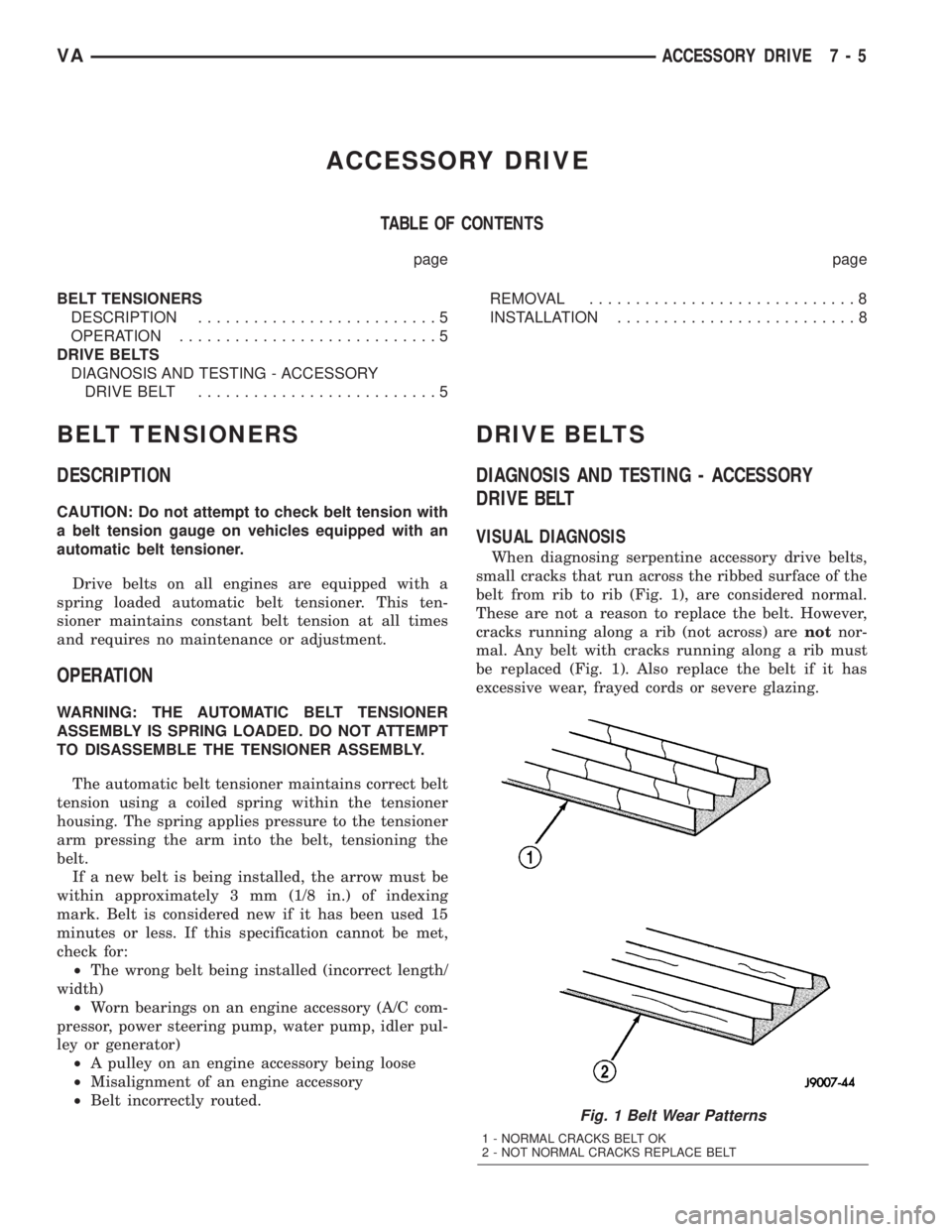
When diagnosing serpentine accessory drive belts,
small cracks that run across the ribbed surface of the
belt from rib to rib (Fig. 1), are considered normal.
These are not a reason to replace the belt. However,
cracks running along a rib (not across) arenotnor-
mal. Any belt with cracks running along a rib must
be replaced (Fig. 1). Also replace the belt if it has
excessive wear, frayed cords or severe glazing.
Fig. 1 Belt Wear Patterns
1 - NORMAL CRACKS BELT OK
2 - NOT NORMAL CRACKS REPLACE BELT
VAACCESSORY DRIVE 7 - 5