2005 MERCEDES-BENZ SPRINTER warning
[x] Cancel search: warningPage 119 of 1232
CHIME/BUZZER
TABLE OF CONTENTS
page page
CHIME/BUZZER
DESCRIPTION..........................1
OPERATION............................1DIAGNOSIS AND TESTING - CHIME
WARNING SYSTEM.....................2
CHIME/BUZZER
DESCRIPTION
A chime warning system is standard factory-installed
equipment. The chime warning system uses a chime
tone generator and a contactless relay that are soldered
onto the electronic circuit board inside the ElectroMe-
chanical Instrument Cluster (EMIC) to provide audible
indications of various vehicle conditions that may
require the attention of the vehicle operator or occu-
pants. The microprocessor-based EMIC utilizes elec-
tronic messages received from other modules in the
vehicle over the Controller Area Network (CAN) data
bus network along with hard wired inputs to the cluster
to monitor many sensors and switches throughout the
vehicle. In response to those inputs, the circuitry and
internal programming of the EMIC allow it to control
audible outputs that are produced through its on-board
chime tone generator and contactless relay.
The EMIC circuitry and its chime tone generator are
capable of producing the following audible outputs:
²Single Chime Tone- A single, extended ªbeep-
likeº chime tone is issued as a seat belt reminder.
²Fast Rate Repetitive Chime Tone- Repeated
ªbeep-likeº tones that are issued at a fast rate as an
audible alert and to support various visual warnings.
²Slow Rate Repetitive Click Tone- Repeated
ªclick-likeº tones that are issued at a slow rate to
emulate turn signal and hazard flasher operation.
²Fast Rate Repetitive Click Tone-
Repeated
ªclick-likeº tones that are issued at a fast rate to emu-
late turn signal flasher operation with a bulb out.
Hard wired circuitry connects the EMIC and the var-
ious chime warning switch and sensor inputs to their
respective modules and to each other through the elec-
trical system of the vehicle. These hard wired circuits
are integral to the vehicle wire harness, which is routed
throughout the vehicle and retained by many different
methods. These circuits may be connected to each other,
to the vehicle electrical system and to the EMIC through
the use of a combination of soldered splices, splice block
connectors, and many different types of wire harness ter-
minal connectors and insulators. Refer to the appropri-
ate wiring information. The wiring information includeswiring diagrams, proper wire and connector repair pro-
cedures, further details on wire harness routing and
retention, as well as pin-out and location views for the
various wire harness connectors, splices and grounds.
The EMIC chime tone generator and contactless
relay cannot be adjusted or repaired. If the chime
tone generator or contactless relay are damaged or
faulty, the entire EMIC unit must be replaced.
OPERATION
The chime warning system components operate on
battery current received through a non-switched
fused B(+) circuit so that the system may operate
regardless of the ignition switch position. The Elec-
tro-Mechanical Instrument Cluster (EMIC) also mon-
itors the ignition switch position so that some chime
features will only occur with ignition switch in the
On position, while others occur regardless of the igni-
tion switch position.
The chime warning system provides an audible
indication to the vehicle operator or occupants under
the following conditions:
²Engine Oil Level Low Warning- Each time
the ignition switch is turned to the On position, the
EMIC chime tone generator will generate a fast rate
repetitive chime tone if electronic messages are
received over the Controller Area Network (CAN)
data bus from the Engine Control Module (ECM)
indicating that the engine level is too low. The ECM
uses internal programming and hard wired inputs
from the engine oil level and temperature sensor to
determine the engine oil level. This audible warning
occurs in concert with the visual warning provided by
the multi-function indicator in the cluster.
²Fasten Seat Belt Reminder- Each time the
ignition switch is turned to the On position, the
EMIC chime tone generator will generate a single
extended chime tone for a duration of about six sec-
onds, or until the driver side front seat belt is fas-
tened, whichever occurs first. The EMIC uses
internal programming and a hard wired input from
the driver side front seat belt switch to determine
the status of the driver side front seat belt. This
audible warning occurs independent of the visual
warning provided by the EMIC ªSeatbeltº indicator.
VACHIME/BUZZER 8B - 1
Page 120 of 1232
²Lights-On Warning- The EMIC chime tone
generator will generate repetitive chime tones at a
fast rate when either front door is opened with the
ignition switch in any position except On, and the
exterior lights are turned On. The EMIC uses inter-
nal programming and hard wired inputs from the left
(lighting) control stalk of the multi-function switch,
the ignition switch, and both front door jamb
switches to determine the current status of these
switches. This chime will continue to sound until the
exterior lighting is turned Off, until the ignition
switch is turned to the On position, or until both
front doors are closed, whichever occurs first.
²Key-In-Ignition Warning-
The EMIC chime
tone generator will generate repetitive chime tones at a
fast rate when the key is in the ignition lock cylinder,
the ignition switch is in any position except On, and
either front door is opened. The EMIC uses internal
programming and hard wired inputs from the key-in
ignition switch, the ignition switch, and both front door
jamb switches to determine the current status of these
switches. The chime will continue to sound until the key
is removed from the ignition lock cylinder, until the
ignition switch is turned to the On position, or until
both front doors are closed, whichever occurs first.
²Audible Turn Signal/Hazard Warning Sup-
port-
The EMIC contactless relay will generate repeti-
tive clicks at a slow rate during normal turn signal/
hazard warning operation, or at a fast rate when a turn
signal lamp bulb or circuit is inoperative, in concert with
the operation of the turn signal indicators in the cluster.
These clicks are designed to emulate the sound of the
opening and closing of the contact points in a conven-
tional electro-mechanical turn signal or hazard warning
flasher. The EMIC uses a hard wired input received from
the turn signal relay in the fuse block beneath the steer-
ing column through the turn signal or hazard warning
switch circuitry of the multi-function switch to determine
when to flash the turn signal indicators and activate the
contactless relay on the cluster electronic circuit board.
The turn signal clicks will continue to sound until the
turn signal switch is turned Off, or until the ignition
switch is turned to the Off position, whichever occurs
first. The hazard warning clicks will continue to sound
until the hazard warning switch is turned Off.
The EMIC provides chime service for all available
features in the chime warning system. The EMIC relies
upon its internal programming and hard wired inputs
from the front door ajar switches, the key-in ignition
switch, the ignition switch, the seat belt switch, and the
turn signal/hazard warning (multi-function) switches.
The EMIC relies upon electronic message inputs
received from other electronic modules over the CAN
data bus network to provide chime service for the low
engine oil level warning. Upon receiving the proper
inputs, the EMIC activates the chime tone generator orthe contactless relay to provide the audible warning to
the vehicle operator. The internal programming of the
EMIC determines the priority of each chime request
input that is received, as well as the rate and duration
of each tone that is to be generated. See the owner's
manual in the vehicle glove box for more information on
the features provided by the chime warning system.
The hard wired chime warning system inputs to
the EMIC, as well as other hard wired circuits for
this system may be diagnosed and tested using con-
ventional diagnostic tools and procedures. However,
conventional diagnostic methods may not prove con-
clusive in the diagnosis of the EMIC, the CAN data
bus network, or the electronic message inputs used
by the EMIC to provide chime warning system ser-
vice. The most reliable, efficient, and accurate means
to diagnose the EMIC, the CAN data bus network,
and the electronic message inputs for the chime
warning system requires the use of a DRBIIItscan
tool. Refer to the appropriate diagnostic information.
DIAGNOSIS AND TESTING - CHIME WARNING
SYSTEM
WARNING: ON VEHICLES EQUIPPED WITH AIRBAGS,
DISABLE THE SUPPLEMENTAL RESTRAINT SYSTEM
BEFORE ATTEMPTING ANY STEERING WHEEL,
STEERING COLUMN, DRIVER AIRBAG, PASSENGER
AIRBAG, SEAT BELT TENSIONER, OR INSTRUMENT
PANEL COMPONENT DIAGNOSIS OR SERVICE. DIS-
CONNECT AND ISOLATE THE BATTERY NEGATIVE
(GROUND) CABLE, THEN WAIT TWO MINUTES FOR
THE SYSTEM CAPACITOR TO DISCHARGE BEFORE
PERFORMING FURTHER DIAGNOSIS OR SERVICE.
THIS IS THE ONLY SURE WAY TO DISABLE THE SUP-
PLEMENTAL RESTRAINT SYSTEM. FAILURE TO TAKE
THE PROPER PRECAUTIONS COULD RESULT IN
ACCIDENTAL AIRBAG DEPLOYMENT AND POSSIBLE
PERSONAL INJURY.
The hard wired chime warning system inputs to
the Electro-Mechanical Instrument Cluster (EMIC),
as well as other hard wired circuits for this system
may be diagnosed and tested using conventional
diagnostic tools and procedures. However, conven-
tional diagnostic methods may not prove conclusive
in the diagnosis of the EMIC, the Controller Area
Network (CAN) data bus network, or the electronic
message inputs used by the EMIC to provide chime
warning system service. The most reliable, efficient,
and accurate means to diagnose the EMIC, the CAN
data bus network, and the electronic message inputs
for the chime warning system requires the use of a
DRBIIItscan tool. Refer to the appropriate diagnos-
tic information.
8B - 2 CHIME/BUZZERVA
CHIME/BUZZER (Continued)
Page 122 of 1232
OPERATION
The central timer module (CTM) monitors many
hard wired switch and sensor inputs as well as those
resources it shares with other modules in the vehicle
through its communication over the programmable
communications interface (PCI) data bus network.
The internal programming and all of these inputs
allow the CTM to determine the tasks it needs to
perform and their priorities, as well as both the stan-
dard and optional features that it should provide.
The CTM then performs those tasks and provides
those features through both PCI data bus communi-
cation with other modules and hard wired outputs
through a number of driver circuits, relays, and
actuators.These outputs allow the CTM the ability to
control numerous accessory systems in the vehicle.
The CTM monitors its own internal circuitry as
well as many of its input and output circuits, and
will store a Diagnostic Trouble Code (DTC) in elec-
tronic memory for any failure it detects. These DTCs
can be retrieved and diagnosed using a DRBIIItscan
tool. Refer to the appropriate diagnostic information.
HARD WIRED INPUTS
The hard wired inputs to the CTM include the fol-
lowing:
²Fused B(+)
²Fused ignition switch output (run-acc)
²Fused ignition switch output (run-start)
²Ground
²Key-in ignition switch sense
²Sliding door switch sense
²Passenger door switch sense
²Driver door switch sense
²PCI bus circuit
HARD WIRED OUTPUTS
The hard wired outputs of the CTM include the fol-
lowing:
²Door lock relay output
²Door unlock relay output
²VTSS indicator driver
MESSAGING
The CTM uses the following messages received
from other electronic modules over the PCI data bus:
²Airbag Deploy (ACM)
²Beep request (CMTC)
²Charging System Failure (PCM)
²Chime request (EMIC)
²Engine RPM (PCM)
²OK to Arm VTSS (PCM)
²Security indicator request (SKIM)
²System Voltage (PCM)
²Valid/Invalid Key (SKIM)
²Vehicle Distance (PCM)²Vehicle Speed (PCM)DIAGNOSIS AND TESTING - CENTRAL TIMER
MODULE
WARNING: ON VEHICLES EQUIPPED WITH AIR-
BAGS, DISABLE THE AIRBAG SYSTEM BEFORE
ATTEMPTING ANY STEERING WHEEL, STEERING
COLUMN, SEAT BELT TENSIONER, OR INSTRU-
MENT PANEL COMPONENT DIAGNOSIS OR SER-
VICE. DISCONNECT AND ISOLATE THE BATTERY
NEGATIVE (GROUND) CABLE, THEN WAIT TWO
MINUTES FOR THE AIRBAG SYSTEM CAPACITOR
TO DISCHARGE BEFORE PERFORMING FURTHER
DIAGNOSIS OR SERVICE. THIS IS THE ONLY SURE
WAY TO DISABLE THE AIRBAG SYSTEM. FAILURE
TO TAKE THE PROPER PRECAUTIONS COULD
RESULT IN ACCIDENTAL AIRBAG DEPLOYMENT
AND POSSIBLE PERSONAL INJURY.
The hard wired inputs to and outputs from the
central timer module (CTM) may be diagnosed and
tested using conventional diagnostic tools and meth-
ods. Refer to the appropriate wiring information.
However, conventional diagnostic methods may not
prove conclusive in the diagnosis of the CTM. In
order to obtain conclusive testing of the CTM, the
programmable communications interface (PCI) data
bus network and all of the modules that provide
inputs to or receive outputs from the CTM must also
be checked. The most reliable, efficient, and accurate
means to diagnose the CTM, the PCI data bus net-
work, and the modules that provide inputs to, or
receive outputs from, the CTM requires the use of a
DRBIIItscan tool. Refer to the appropriate diagnos-
tic information.
REMOVAL
(1) Disconnect and isolate the battery negative
cable.
(2) Slide the driver seat to the full forward posi-
tion.
(3) Disconnect the wire harness connector for the
seat belt latch. (Fig. 1).
(4) Remove the screws that secure the closeout
panel beneathe the driver seat cushion and remove
the panel.
(5) Remove the screws that secure the central
timer module to the bracket.
(6) Disconnect the wire harness connectors from
the central timer module.
(7) Remove the central timer module from the
vehicle.
INSTALLATION
(1) Position the central timer module in the vehicle
8E - 2 ELECTRONIC CONTROL MODULESVA
CENTRAL TIMER MODULE (Continued)
Page 135 of 1232
lead dioxide (positive plate) or sponge lead (negative
plate). Insulators or plate separators made of a non-
conductive material are inserted between the positive
and negative plates to prevent them from contacting
or shorting against one another. These dissimilar
metal plates are submerged in a sulfuric acid and
water solution called an electrolyte.
The factory-installed low-maintenance bat-
tery has removable battery cell caps.Water can
be added to this battery. The chemical composition of
the metal coated plates within the low-maintenance
battery reduces battery gassing and water loss, at
normal charge and discharge rates. Therefore, the
battery should not require additional water in nor-
mal service. Rapid loss of electrolyte can be caused
by an overcharging condition. Be certain to diagnose
the charging system before returning the vehicle to
service.
OPERATION
The battery is designed to store electrical energy in
a chemical form. When an electrical load is applied to
the terminals of the battery, an electrochemical reac-
tion occurs. This reaction causes the battery to dis-
charge electrical current from its terminals. As the
battery discharges, a gradual chemical change takes
place within each cell. The sulfuric acid in the elec-
trolyte combines with the plate materials, causing
both plates to slowly change to lead sulfate. At the
same time, oxygen from the positive plate material
combines with hydrogen from the sulfuric acid, caus-
ing the electrolyte to become mainly water. The
chemical changes within the battery are caused by
the movement of excess or free electrons between the
positive and negative plate groups. This movement of
electrons produces a flow of electrical current
through the load device attached to the battery ter-
minals.
As the plate materials become more similar chem-
ically, and the electrolyte becomes less acid, the volt-
age potential of each cell is reduced. However, by
charging the battery with a voltage higher than that
of the battery itself, the battery discharging process
is reversed. Charging the battery gradually changes
the sulfated lead plates back into sponge lead and
lead dioxide, and the water back into sulfuric acid.
This action restores the difference in the electron
charges deposited on the plates, and the voltage
potential of the battery cells. For a battery to remain
useful, it must be able to produce high-amperage cur-
rent over an extended period. A battery must also be
able to accept a charge, so that its voltage potential
may be restored.
The battery is vented to release excess hydrogen
gas that is created when the battery is being charged
or discharged. However, even with these vents,hydrogen gas can collect in or around the battery. If
hydrogen gas is exposed to flame or sparks, it may
ignite. If the electrolyte level is low, the battery may
arc internally and explode. If the battery is equipped
with removable cell caps, add distilled water when-
ever the electrolyte level is below the top of the
plates. If the battery cell caps cannot be removed, the
battery must be replaced if the electrolyte level
becomes low.
DIAGNOSIS AND TESTING - BATTERY
The battery must be completely charged and the
terminals should be properly cleaned and inspected
before diagnostic procedures are performed. Refer to
Battery System Cleaning for the proper cleaning pro-
cedures, and Battery System Inspection for the
proper battery inspection procedures. Refer to Stan-
dard Procedures for the proper battery charging pro-
cedures.
MICRO 420 BATTERY TESTER
The Micro 420 automotive battery tester is
designed to help the dealership technicians diagnose
the cause of a defective battery. Follow the instruc-
tion manual supplied with the tester to properly
diagnose a vehicle. If the instruction manual is not
available refer to the standard procedure in this sec-
tion, which includes the directions for using the
Micro 420 battery tester.
WARNING: IF THE BATTERY SHOWS SIGNS OF
FREEZING, LEAKING OR LOOSE POSTS, DO NOT
TEST, ASSIST-BOOST, OR CHARGE. THE BATTERY
MAY ARC INTERNALLY AND EXPLODE. PERSONAL
INJURY AND/OR VEHICLE DAMAGE MAY RESULT.
WARNING: EXPLOSIVE HYDROGEN GAS FORMS IN
AND AROUND THE BATTERY. DO NOT SMOKE,
USE FLAME, OR CREATE SPARKS NEAR THE BAT-
TERY. PERSONAL INJURY AND/OR VEHICLE DAM-
AGE MAY RESULT.
WARNING: THE BATTERY CONTAINS SULFURIC
ACID, WHICH IS POISONOUS AND CAUSTIC. AVOID
CONTACT WITH THE SKIN, EYES, OR CLOTHING.
IN THE EVENT OF CONTACT, FLUSH WITH WATER
AND CALL A PHYSICIAN IMMEDIATELY. KEEP OUT
OF THE REACH OF CHILDREN.
A battery that will not accept a charge is faulty,
and must be replaced. Further testing is not
required. A fully-charged battery must be tested to
determine its cranking capacity. A battery that is ful-
ly-charged, but does not pass the Micro 420 or load
test, is faulty and must be replaced.
VABATTERY SYSTEM 8F - 7
BATTERY (Continued)
Page 136 of 1232
NOTE: Completely discharged batteries may take
several hours to accept a charge. Refer to Standard
Procedures for the proper battery charging proce-
dures.
STANDARD PROCEDURE
STANDARD PROCEDURE - BATTERY
CHARGING
Battery charging is the means by which the bat-
tery can be restored to its full voltage potential. A
battery is fully-charged when:
²Micro 420 electrical system tester indicates bat-
tery is OK.
²Three hydrometer tests, taken at one-hour inter-
vals, indicate no increase in the temperature-cor-
rected specific gravity of the battery electrolyte.
²Passes Load test.
²Open-circuit voltage of the battery is 12.65 volts
or above.
WARNING: IF THE BATTERY SHOWS SIGNS OF
FREEZING, LEAKING OR LOOSE POSTS, DO NOT
TEST, ASSIST-BOOST, OR CHARGE. THE BATTERY
MAY ARC INTERNALLY AND EXPLODE. PERSONAL
INJURY AND/OR VEHICLE DAMAGE MAY RESULT.
WARNING: EXPLOSIVE HYDROGEN GAS FORMS IN
AND AROUND THE BATTERY. DO NOT SMOKE,
USE FLAME, OR CREATE SPARKS NEAR THE BAT-
TERY. PERSONAL INJURY AND/OR VEHICLE DAM-
AGE MAY RESULT.
WARNING: THE BATTERY CONTAINS SULFURIC
ACID, WHICH IS POISONOUS AND CAUSTIC. AVOID
CONTACT WITH THE SKIN, EYES, OR CLOTHING.
IN THE EVENT OF CONTACT, FLUSH WITH WATER
AND CALL A PHYSICIAN IMMEDIATELY. KEEP OUT
OF THE REACH OF CHILDREN.
WARNING: IF THE BATTERY IS EQUIPPED WITH
REMOVABLE CELL CAPS, BE CERTAIN THAT EACH
OF THE CELL CAPS IS IN PLACE AND TIGHT
BEFORE THE BATTERY IS RETURNED TO SER-
VICE. PERSONAL INJURY AND/OR VEHICLE DAM-AGE MAY RESULT FROM LOOSE OR MISSING
CELL CAPS.
CAUTION: Always disconnect and isolate the bat-
tery negative cable before charging a battery. Do
not exceed sixteen volts while charging a battery.
Damage to the vehicle electrical system compo-
nents may result.
CAUTION: Battery electrolyte will bubble inside the
battery case during normal battery charging. Elec-
trolyte boiling or being discharged from the battery
vents indicates a battery overcharging condition.
Immediately reduce the charging rate or turn off the
charger to evaluate the battery condition. Damage
to the battery may result from overcharging.
CAUTION: The battery should not be hot to the
touch. If the battery feels hot to the touch, turn off
the charger and let the battery cool before continu-
ing the charging operation. Damage to the battery
may result.
Some battery chargers are equipped with polarity-
sensing circuitry. This circuitry protects the battery
charger and the battery from being damaged if they
are improperly connected. If the battery state-of-
charge is too low for the polarity-sensing circuitry to
detect, the battery charger will not operate. This
makes it appear that the battery will not accept
charging current. See the instructions provided by
the manufacturer of the battery charger for details
on how to bypass the polarity-sensing circuitry.
After the battery has been charged to 12.4 volts or
greater, retest the battery using the Micro 420 tester
or perform a load test to determine the battery
cranking capacity. If the battery will endure a load
test, return the battery to service. If the battery will
not endure a load test, it is faulty and must be
replaced.
Clean and inspect the battery hold downs, tray,
terminals, posts, and top before completing battery
service. Refer to Battery System Cleaning for the
proper battery system cleaning procedures, and Bat-
tery System Inspection for the proper battery system
inspection procedures.
8F - 8 BATTERY SYSTEMVA
BATTERY (Continued)
Page 139 of 1232
battery negative terminal post and the negative cable
terminal clamp is lost during any part of the IOD
test, the electronic timer function will be activated
and all of the tests will have to be repeated.
(5) After about three minutes, the high-amperage
IOD reading on the multi-meter should become very
low or nonexistent, depending upon the electrical
equipment in the vehicle. If the amperage reading
remains high, remove and replace each fuse or circuit
breaker in the Fuse Blocks, one at a time until the
amperage reading becomes very low, or nonexistent.
Refer to the appropriate wiring information in this
service manual for complete fuseblock fuse, circuit
breaker, and circuit identification. This will isolate
each circuit and identify the circuit that is the source
of the high-amperage IOD. If the amperage reading
remains high after removing and replacing each fuse
and circuit breaker, disconnect the wire harness from
the generator. If the amperage reading now becomes
very low or nonexistent, refer to Charging System for
the proper charging system diagnosis and testing
procedures. After the high-amperage IOD has been
corrected, switch the multi-meter to progressively
lower amperage scales and, if necessary, repeat the
fuse and circuit breaker remove-and-replace process
to identify and correct all sources of excessive IOD. It
is now safe to select the lowest milliampere scale of
the multi-meter to check the low-amperage IOD.
CAUTION: Do not open any doors, or turn on any
electrical accessories with the lowest milliampere
scale selected, or the multi-meter may be damaged.
(6) Observe the multi-meter reading. The low-am-
perage IOD should not exceed thirty-five milliam-
peres (0.035 ampere). If the current draw exceeds
thirty-five milliamperes, isolate each circuit using the
fuse and circuit breaker remove-and-replace process
in Step 5. The multi-meter reading will drop to
within the acceptable limit when the source of the
excessive current draw is disconnected. Repair this
circuit as required; whether a wiring short, incorrect
switch adjustment, or a component failure is at fault.
STANDARD PROCEDURE - USING MICRO 420
BATTERY TESTER
Always use the Micro 420 Instruction Manual that
was supplied with the tester as a reference. If the
Instruction Manual is not available the following pro-
cedure can be used:
WARNING: ALWAYS WEAR APPROPRIATE EYE
PROTECTION AND USE EXTREME CAUTION WHEN
WORKING WITH BATTERIES.
BATTERY TESTING
(1) If testing the battery OUT-OF-VEHICLE, clean
the battery terminals with a wire brush before test-
ing. If the battery is equipped with side post termi-
nals, install and tighten the supplied lead terminal
stud adapters. Do not use steel bolts. Failure to prop-
erly install the stud adapters, or using stud adapters
that are dirty or worn-out may result in false test
readings.
(2) If testing the battery IN-THE-VEHICLE, make
certain all of the vehicle accessory loads are OFF,
including the ignition.The preferred test position
is at the battery terminal. If the battery is not
accessible, you may test using both the positive and
negative jumper posts. Select TESTING AT JUMPER
POST when connecting to that location.
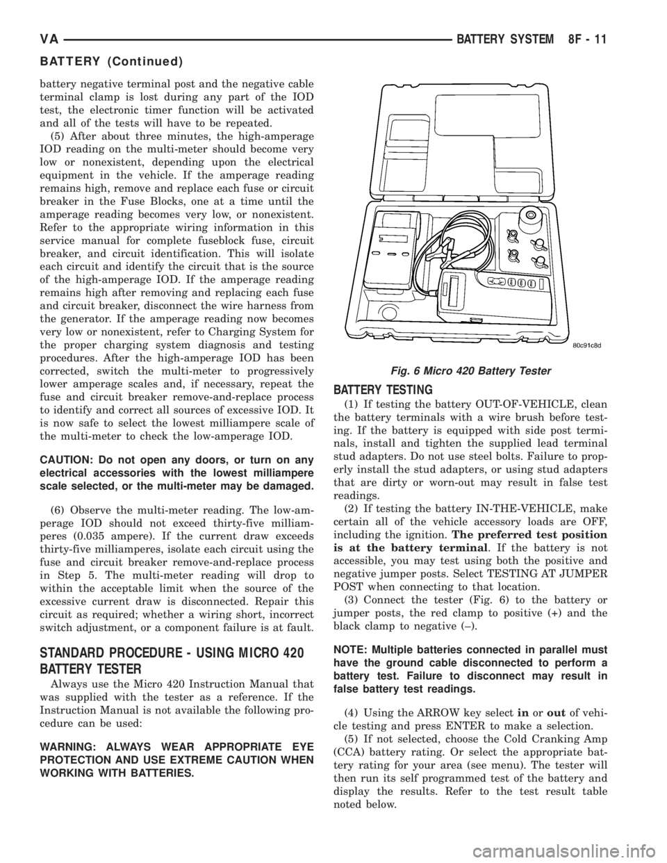
(3) Connect the tester (Fig. 6) to the battery or
jumper posts, the red clamp to positive (+) and the
black clamp to negative (±).
NOTE: Multiple batteries connected in parallel must
have the ground cable disconnected to perform a
battery test. Failure to disconnect may result in
false battery test readings.
(4) Using the ARROW key selectinoroutof vehi-
cle testing and press ENTER to make a selection.
(5) If not selected, choose the Cold Cranking Amp
(CCA) battery rating. Or select the appropriate bat-
tery rating for your area (see menu). The tester will
then run its self programmed test of the battery and
display the results. Refer to the test result table
noted below.
Fig. 6 Micro 420 Battery Tester
VABATTERY SYSTEM 8F - 11
BATTERY (Continued)
Page 141 of 1232
essary, use a battery terminal puller to remove the
terminal clamp from the battery post.
(6) Remove the battery hold downs from the bat-
tery (Refer to 8 - ELECTRICAL/BATTERY SYSTEM/
BATTERY HOLDDOWN - REMOVAL).
WARNING: WEAR A SUITABLE PAIR OF RUBBER
GLOVES (NOT THE HOUSEHOLD TYPE) WHEN
REMOVING A BATTERY BY HAND. SAFETY
GLASSES SHOULD ALSO BE WORN. IF THE BAT-
TERY IS CRACKED OR LEAKING, THE ELECTRO-
LYTE CAN BURN THE SKIN AND EYES.
(7) Remove the battery from the battery tray.
AUXILIARY BATTERY REMOVAL
(1) Turn the ignition switch to the Off position. Be
certain that all electrical accessories are turned off.
(2) Remove the passenger front seat assembly.
Refer to the Body section for procedure.
(3) Remove the top cover from the seat base
assembly.
(4) Loosen the battery negative cable terminal
clamp pinch-bolt hex nut.
(5) Disconnect the battery negative cable terminal
clamp from the battery negative terminal post. If
necessary, use a battery terminal puller to remove
the terminal clamp from the battery post.
(6) Loosen the battery positive cable terminal
clamp pinch-bolt hex nut.
(7) Disconnect the battery positive cable terminal
clamp from the battery positive terminal post. If nec-
essary, use a battery terminal puller to remove the
terminal clamp from the battery post.
(8) Remove the battery hold downs from the bat-
tery (Refer to 8 - ELECTRICAL/BATTERY SYSTEM/
BATTERY HOLDDOWN - REMOVAL).
WARNING: WEAR A SUITABLE PAIR OF RUBBER
GLOVES (NOT THE HOUSEHOLD TYPE) WHEN
REMOVING A BATTERY BY HAND. SAFETY
GLASSES SHOULD ALSO BE WORN. IF THE BAT-
TERY IS CRACKED OR LEAKING, THE ELECTRO-
LYTE CAN BURN THE SKIN AND EYES.
(9) Remove the battery from the battery tray.
INSTALLATION
UNDER HOOD BATTERY INSTALLATION
(1) Position the battery onto the battery tray.
Ensure that the battery positive and negative termi-
nal posts are correctly positioned. The battery cable
terminal clamps must reach the correct battery ter-
minal post without stretching the cables.(2) Reinstall the battery hold downs onto the bat-
tery (Refer to 8 - ELECTRICAL/BATTERY SYSTEM/
BATTERY HOLDDOWN - INSTALLATION).
CAUTION: Be certain that the battery cable terminal
clamps are connected to the correct battery termi-
nal posts. Reverse battery polarity may damage
electrical components of the vehicle.
(3) Reconnect the battery positive cable terminal
clamp to the battery positive terminal post. Tighten
the terminal clamp pinch-bolt hex nut to 11.8 N´m
(105 in. lbs.).
(4) Reconnect the battery negative cable terminal
clamp to the battery negative terminal post. Tighten
the terminal clamp pinch-bolt hex nut to 7.9 N´m (70
in. lbs.).
(5) Apply a thin coating of petroleum jelly or chas-
sis grease to the exposed surfaces of the battery cable
terminal clamps and the battery terminal posts.
AUXILIARY BATTERY INSTALLATION
(1) Position the battery onto the battery tray.
Ensure that the battery positive and negative termi-
nal posts are correctly positioned. The battery cable
terminal clamps must reach the correct battery ter-
minal post without stretching the cables.
(2) Reinstall the battery hold downs onto the bat-
tery (Refer to 8 - ELECTRICAL/BATTERY SYSTEM/
BATTERY HOLDDOWN - INSTALLATION).
CAUTION: Be certain that the battery cable terminal
clamps are connected to the correct battery termi-
nal posts. Reverse battery polarity may damage
electrical components of the vehicle.
(3) Reconnect the battery positive cable terminal
clamp to the battery positive terminal post. Tighten
the terminal clamp pinch-bolt hex nut to 11.8 N´m
(105 in. lbs.).
(4) Reconnect the battery negative cable terminal
clamp to the battery negative terminal post. Tighten
the terminal clamp pinch-bolt hex nut to 7.9 N´m (70
in. lbs.).
(5) Apply a thin coating of petroleum jelly or chas-
sis grease to the exposed surfaces of the battery cable
terminal clamps and the battery terminal posts.
(6) Install the top cover on the seat base assembly.
(7) Install the passenger front seat assembly. Refer
to the Body section for procedure.
VABATTERY SYSTEM 8F - 13
BATTERY (Continued)
Page 142 of 1232
BATTERY HOLDDOWN
DESCRIPTION
The battery hold down hardware includes two hex
nuts with washers and two hold down brackets. The
battery hold down brackets are formed of stamped
steel. The hold down assembly is coated for corrosion
protection.
When installing a battery into the battery tray, be
certain that the hold down hardware is properly
installed and that the fasteners are tightened to the
proper specifications. Improper hold down fastener
tightness, whether too loose or too tight, can result in
damage to the battery, the vehicle or both.
REMOVAL
(1) Turn the ignition switch to the Off position. Be
certain that all electrical accessories are turned off.
(2) Remove the two nuts that secure the battery
hold down brackets to the battery tray.
(3) Remove the battery hold down brackets.
INSTALLATION
(1) Install the battery hold down brackets.
(2) Install the two nuts that secure the battery
hold down brackets to the battery tray. Tighten to 70
in. lbs.
BATTERY CABLES
DESCRIPTION
The battery cables are large gauge, stranded cop-
per wires sheathed within a heavy plastic or syn-
thetic rubber insulating jacket. The wire used in the
battery cables combines excellent flexibility and reli-
ability with high electrical current carrying capacity.
The battery cables cannot be repaired and, if dam-
aged or faulty they must be replaced. Both the bat-
tery positive and negative cables are available for
service replacement only as a unit with the battery
positive cable wire harness or the battery negative
cable wire harness, which may include portions of
the wiring circuits for the generator and other com-
ponents on some models.
The battery cables feature a stamped brass clamp-
ing type female battery terminal crimped onto one
end of the battery cable wire and then solder-dipped.
A square headed pinch-bolt and hex nut are installed
at the open end of the female battery terminal clamp.
The battery positive cable also includes a red molded
rubber protective cover for the female battery termi-
nal clamp. Large eyelet type terminals are crimped
onto the opposite end of the battery cable wire and
then solder-dipped. The battery positive cable wires
have a red insulating jacket to provide visual identi-fication and feature a larger female battery terminal
clamp to allow connection to the larger battery posi-
tive terminal post. The battery negative cable wires
have a black insulating jacket and a smaller female
battery terminal clamp.
OPERATION
The battery cables connect the battery terminal
posts to the vehicle electrical system. These cables
also provide a return path for electrical current gen-
erated by the charging system for restoring the volt-
age potential of the battery. The female battery
terminal clamps on the ends of the battery cable
wires provide a strong and reliable connection of the
battery cable to the battery terminal posts. The ter-
minal pinch bolts allow the female terminal clamps
to be tightened around the male terminal posts on
the top of the battery. The eyelet terminals secured
to the ends of the battery cable wires opposite the
female battery terminal clamps provide secure and
reliable connection of the battery to the vehicle elec-
trical system.
DIAGNOSIS AND TESTING - BATTERY CABLES
A voltage drop test will determine if there is exces-
sive resistance in the battery cable terminal connec-
tions or the battery cables. If excessive resistance is
found in the battery cable connections, the connec-
tion point should be disassembled, cleaned of all cor-
rosion or foreign material, then reassembled.
Following reassembly, check the voltage drop for the
battery cable connection and the battery cable again
to confirm repair.
When performing the voltage drop test, it is impor-
tant to remember that the voltage drop is giving an
indication of the resistance between the two points at
which the voltmeter probes are attached.EXAM-
PLE:When testing the resistance of the battery pos-
itive cable, touch the voltmeter leads to the battery
positive cable terminal clamp and to the battery pos-
itive cable eyelet terminal at the starter solenoid
B(+) terminal stud. If you probe the battery positive
terminal post and the battery positive cable eyelet
terminal at the starter solenoid B(+) terminal stud,
you are reading the combined voltage drop in the
battery positive cable terminal clamp-to-terminal
post connection and the battery positive cable.
VOLTAGE DROP TEST
WARNING: IF THE BATTERY SHOWS SIGNS OF
FREEZING, LEAKING, LOOSE POSTS, OR LOW
ELECTROLYTE LEVEL, DO NOT TEST, ASSIST-
BOOST, OR CHARGE. THE BATTERY MAY ARC
INTERNALLY AND EXPLODE. PERSONAL INJURY
AND/OR VEHICLE DAMAGE MAY RESULT.
8F - 14 BATTERY SYSTEMVA