2005 MERCEDES-BENZ SPRINTER oil capacity
[x] Cancel search: oil capacityPage 14 of 1232
Full synthetic oils, such as Mobilt1 0W-40, is
required if the ASSYST Oil Service Reminder is fol-
lowed. Use of a lower quality oil on this service
schedule may cause severe engine damage.
DESCRIPTION - AUTOMATIC TRANSMISSION
FLUID - NAG1
NOTE: Refer to Service Procedures in this group for
fluid level checking procedures.
Shellt3403 Automatic Transmission Fluid is the
recommended fluid for the NAG1 DaimlerChrysler
automatic transmission.
Dexron II fluid IS NOT recommended. Clutch
chatter can result from the use of improper
fluid.
MopartATF+4, Automatic Transmission Fluid, or
other fluids meeting MS-9602, may be used if Shellt
3403 Automatic Transmission Fluid is not available.
Shellt3403 Automatic Transmission Fluid when
new is red in color. The ATF is dyed red so it can be
identified from other fluids used in the vehicle such
as engine oil or antifreeze. The red color is not per-
manent and is not an indicator of fluid condition. As
the vehicle is driven, the ATF will begin to look
darker in color and may eventually become brown.
This is normal.
FLUID ADDITIVES
DaimlerChrysler strongly recommends against the
addition of any fluids to the transmission, other than
those automatic transmission fluids listed above.
Exceptions to this policy are the use of special dyes
to aid in detecting fluid leaks.
Various ªspecialº additives and supplements exist
that claim to improve shift feel and/or quality. These
additives and others also claim to improve converter
clutch operation and inhibit overheating, oxidation,
varnish, and sludge. These claims have not been sup-
ported to the satisfaction of DaimlerChrysler and
these additivesmust not be used.The use of trans-
mission ªsealersº should also be avoided, since they
may adversely affect the integrity of transmission
seals.
OPERATION - AUTOMATIC TRANSMISSION
FLUID
The automatic transmission fluid is selected based
upon several qualities. The fluid must provide a high
level of protection for the internal components by
providing a lubricating film between adjacent metal
components. The fluid must also be thermally stable
so that it can maintain a consistent viscosity through
a large temperature range. If the viscosity stays con-
stant through the temperature range of operation,transmission operation and shift feel will remain con-
sistent. Transmission fluid must also be a good con-
ductor of heat. The fluid must absorb heat from the
internal transmission components and transfer that
heat to the transmission case.
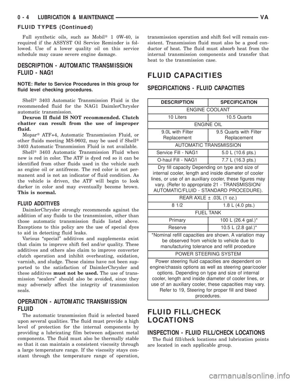
FLUID CAPACITIES
SPECIFICATIONS - FLUID CAPACITIES
DESCRIPTION SPECIFICATION
ENGINE COOLANT
10 Liters 10.5 Quarts
ENGINE OIL
9.0L with Filter
Replacement9.5 Quarts with Filter
Replacement
AUTOMATIC TRANSMISSION
Service Fill - NAG1 5.0 L (10.6 pts.)
O-haul Fill - NAG1 7.7 L (16.3 pts.)
Dry fill capacity Depending on type and size of
internal cooler, length and inside diameter of cooler
lines, or use of an auxiliary cooler, these figures may
vary. (Refer to appropriate 21 - TRANSMISSION/
AUTOMATIC/FLUID - STANDARD PROCEDURE).
REAR AXLE .03L (1 oz.)
8 1/2 1.8 L (4.0 pts.)
FUEL TANK
Primary 100 L (26.4 gal.)*
Reserve 10.5 L (2.8 gal.)*
*Nominal refill capacities are shown. A variation may
be observed from vehicle to vehicle due to
manufacturing tolerance and refill procedure
POWER STEERING SYSTEM
Power steering fluid capacities are dependent on
engine/chassis options as well as steering gear/cooler
options. Depending on type and size of internal
cooler, length and inside diameter of cooler lines, or
use of an auxiliary cooler, these capacities may vary.
Refer to 19, Steering for proper fill and bleed
procedures.
FLUID FILL/CHECK
LOCATIONS
INSPECTION - FLUID FILL/CHECK LOCATIONS
The fluid fill/check locations and lubrication points
are located in each applicable group.
0 - 4 LUBRICATION & MAINTENANCEVA
FLUID TYPES (Continued)
Page 114 of 1232
(16) Install A/C condenser.
(17) Install front bumper.
(18) Install front end cross member.
(19) Refill power steering to proper level.
(20) Refill transmission to proper level.
(21) Close radiator drain plug and refill the cooling
system to the correct level with the appropriate cool-
ant mixture.
(22) Recharge air conditioning.
(23) Run engine until warm and check for leaks.
RADIATOR PRESSURE CAP
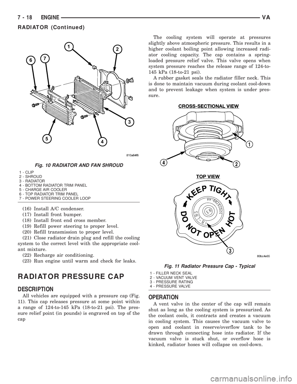
DESCRIPTION
All vehicles are equipped with a pressure cap (Fig.
11). This cap releases pressure at some point within
a range of 124-to-145 kPa (18-to-21 psi). The pres-
sure relief point (in pounds) is engraved on top of the
capThe cooling system will operate at pressures
slightly above atmospheric pressure. This results in a
higher coolant boiling point allowing increased radi-
ator cooling capacity. The cap contains a spring-
loaded pressure relief valve. This valve opens when
system pressure reaches the release range of 124-to-
145 kPa (18-to-21 psi).
A rubber gasket seals the radiator filler neck. This
is done to maintain vacuum during coolant cool-down
and to prevent leakage when system is under pres-
sure.OPERATION
A vent valve in the center of the cap will remain
shut as long as the cooling system is pressurized. As
the coolant cools, it contracts and creates a vacuum
in cooling system. This causes the vacuum valve to
open and coolant in reserve/overflow tank to be
drawn through connecting hose into radiator. If the
vacuum valve is stuck shut, or overflow hose is
kinked, radiator hoses will collapse on cool-down.
Fig. 10 RADIATOR AND FAN SHROUD
1 - CLIP
2 - SHROUD
3 - RADIATOR
4 - BOTTOM RADIATOR TRIM PANEL
5 - CHARGE AIR COOLER
6 - TOP RADIATOR TRIM PANEL
7 - POWER STEERING COOLER LOOP
Fig. 11 Radiator Pressure Cap - Typical
1 - FILLER NECK SEAL
2 - VACUUM VENT VALVE
3 - PRESSURE RATING
4 - PRESSURE VALVE
7 - 18 ENGINEVA
RADIATOR (Continued)
Page 136 of 1232
NOTE: Completely discharged batteries may take
several hours to accept a charge. Refer to Standard
Procedures for the proper battery charging proce-
dures.
STANDARD PROCEDURE
STANDARD PROCEDURE - BATTERY
CHARGING
Battery charging is the means by which the bat-
tery can be restored to its full voltage potential. A
battery is fully-charged when:
²Micro 420 electrical system tester indicates bat-
tery is OK.
²Three hydrometer tests, taken at one-hour inter-
vals, indicate no increase in the temperature-cor-
rected specific gravity of the battery electrolyte.
²Passes Load test.
²Open-circuit voltage of the battery is 12.65 volts
or above.
WARNING: IF THE BATTERY SHOWS SIGNS OF
FREEZING, LEAKING OR LOOSE POSTS, DO NOT
TEST, ASSIST-BOOST, OR CHARGE. THE BATTERY
MAY ARC INTERNALLY AND EXPLODE. PERSONAL
INJURY AND/OR VEHICLE DAMAGE MAY RESULT.
WARNING: EXPLOSIVE HYDROGEN GAS FORMS IN
AND AROUND THE BATTERY. DO NOT SMOKE,
USE FLAME, OR CREATE SPARKS NEAR THE BAT-
TERY. PERSONAL INJURY AND/OR VEHICLE DAM-
AGE MAY RESULT.
WARNING: THE BATTERY CONTAINS SULFURIC
ACID, WHICH IS POISONOUS AND CAUSTIC. AVOID
CONTACT WITH THE SKIN, EYES, OR CLOTHING.
IN THE EVENT OF CONTACT, FLUSH WITH WATER
AND CALL A PHYSICIAN IMMEDIATELY. KEEP OUT
OF THE REACH OF CHILDREN.
WARNING: IF THE BATTERY IS EQUIPPED WITH
REMOVABLE CELL CAPS, BE CERTAIN THAT EACH
OF THE CELL CAPS IS IN PLACE AND TIGHT
BEFORE THE BATTERY IS RETURNED TO SER-
VICE. PERSONAL INJURY AND/OR VEHICLE DAM-AGE MAY RESULT FROM LOOSE OR MISSING
CELL CAPS.
CAUTION: Always disconnect and isolate the bat-
tery negative cable before charging a battery. Do
not exceed sixteen volts while charging a battery.
Damage to the vehicle electrical system compo-
nents may result.
CAUTION: Battery electrolyte will bubble inside the
battery case during normal battery charging. Elec-
trolyte boiling or being discharged from the battery
vents indicates a battery overcharging condition.
Immediately reduce the charging rate or turn off the
charger to evaluate the battery condition. Damage
to the battery may result from overcharging.
CAUTION: The battery should not be hot to the
touch. If the battery feels hot to the touch, turn off
the charger and let the battery cool before continu-
ing the charging operation. Damage to the battery
may result.
Some battery chargers are equipped with polarity-
sensing circuitry. This circuitry protects the battery
charger and the battery from being damaged if they
are improperly connected. If the battery state-of-
charge is too low for the polarity-sensing circuitry to
detect, the battery charger will not operate. This
makes it appear that the battery will not accept
charging current. See the instructions provided by
the manufacturer of the battery charger for details
on how to bypass the polarity-sensing circuitry.
After the battery has been charged to 12.4 volts or
greater, retest the battery using the Micro 420 tester
or perform a load test to determine the battery
cranking capacity. If the battery will endure a load
test, return the battery to service. If the battery will
not endure a load test, it is faulty and must be
replaced.
Clean and inspect the battery hold downs, tray,
terminals, posts, and top before completing battery
service. Refer to Battery System Cleaning for the
proper battery system cleaning procedures, and Bat-
tery System Inspection for the proper battery system
inspection procedures.
8F - 8 BATTERY SYSTEMVA
BATTERY (Continued)
Page 1035 of 1232
WHEELS
DESCRIPTION
Original equipment wheels are designed for the
specified Maximum Vehicle Capacity.
All models use steel or aluminum wheels.
Aluminum wheels require special balance weights
and alignment equipment.
(1) On vehicles equipped with dual rear wheels,
The slots in the wheel must be aligned to provide
access to the valve stem.
OPERATION
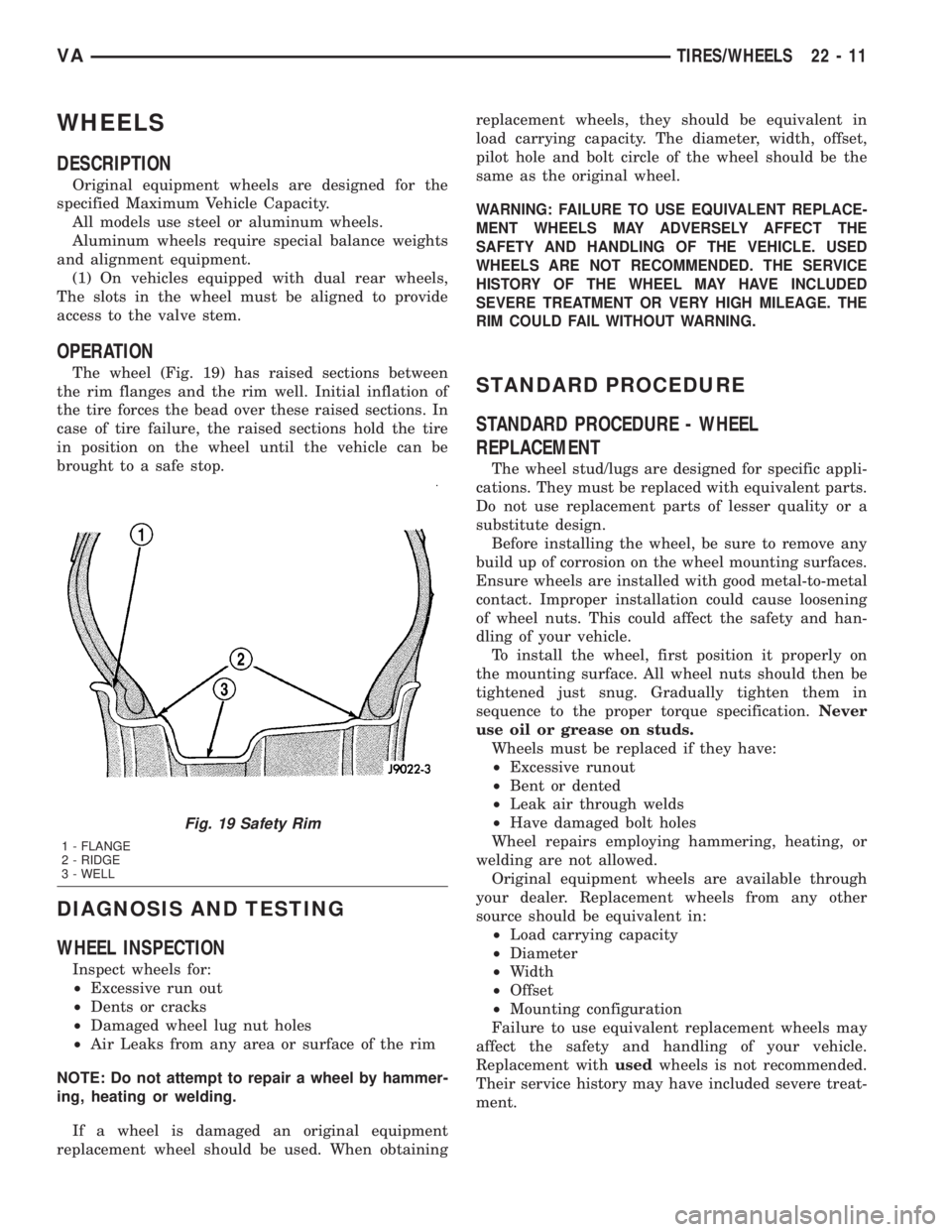
The wheel (Fig. 19) has raised sections between
the rim flanges and the rim well. Initial inflation of
the tire forces the bead over these raised sections. In
case of tire failure, the raised sections hold the tire
in position on the wheel until the vehicle can be
brought to a safe stop.
DIAGNOSIS AND TESTING
WHEEL INSPECTION
Inspect wheels for:
²Excessive run out
²Dents or cracks
²Damaged wheel lug nut holes
²Air Leaks from any area or surface of the rim
NOTE: Do not attempt to repair a wheel by hammer-
ing, heating or welding.
If a wheel is damaged an original equipment
replacement wheel should be used. When obtainingreplacement wheels, they should be equivalent in
load carrying capacity. The diameter, width, offset,
pilot hole and bolt circle of the wheel should be the
same as the original wheel.
WARNING: FAILURE TO USE EQUIVALENT REPLACE-
MENT WHEELS MAY ADVERSELY AFFECT THE
SAFETY AND HANDLING OF THE VEHICLE. USED
WHEELS ARE NOT RECOMMENDED. THE SERVICE
HISTORY OF THE WHEEL MAY HAVE INCLUDED
SEVERE TREATMENT OR VERY HIGH MILEAGE. THE
RIM COULD FAIL WITHOUT WARNING.
STANDARD PROCEDURE
STANDARD PROCEDURE - WHEEL
REPLACEMENT
The wheel stud/lugs are designed for specific appli-
cations. They must be replaced with equivalent parts.
Do not use replacement parts of lesser quality or a
substitute design.
Before installing the wheel, be sure to remove any
build up of corrosion on the wheel mounting surfaces.
Ensure wheels are installed with good metal-to-metal
contact. Improper installation could cause loosening
of wheel nuts. This could affect the safety and han-
dling of your vehicle.
To install the wheel, first position it properly on
the mounting surface. All wheel nuts should then be
tightened just snug. Gradually tighten them in
sequence to the proper torque specification.Never
use oil or grease on studs.
Wheels must be replaced if they have:
²Excessive runout
²Bent or dented
²Leak air through welds
²Have damaged bolt holes
Wheel repairs employing hammering, heating, or
welding are not allowed.
Original equipment wheels are available through
your dealer. Replacement wheels from any other
source should be equivalent in:
²Load carrying capacity
²Diameter
²Width
²Offset
²Mounting configuration
Failure to use equivalent replacement wheels may
affect the safety and handling of your vehicle.
Replacement withusedwheels is not recommended.
Their service history may have included severe treat-
ment.
Fig. 19 Safety Rim
1 - FLANGE
2 - RIDGE
3 - WELL
VATIRES/WHEELS 22 - 11
Page 1133 of 1232
SPECIFICATIONS
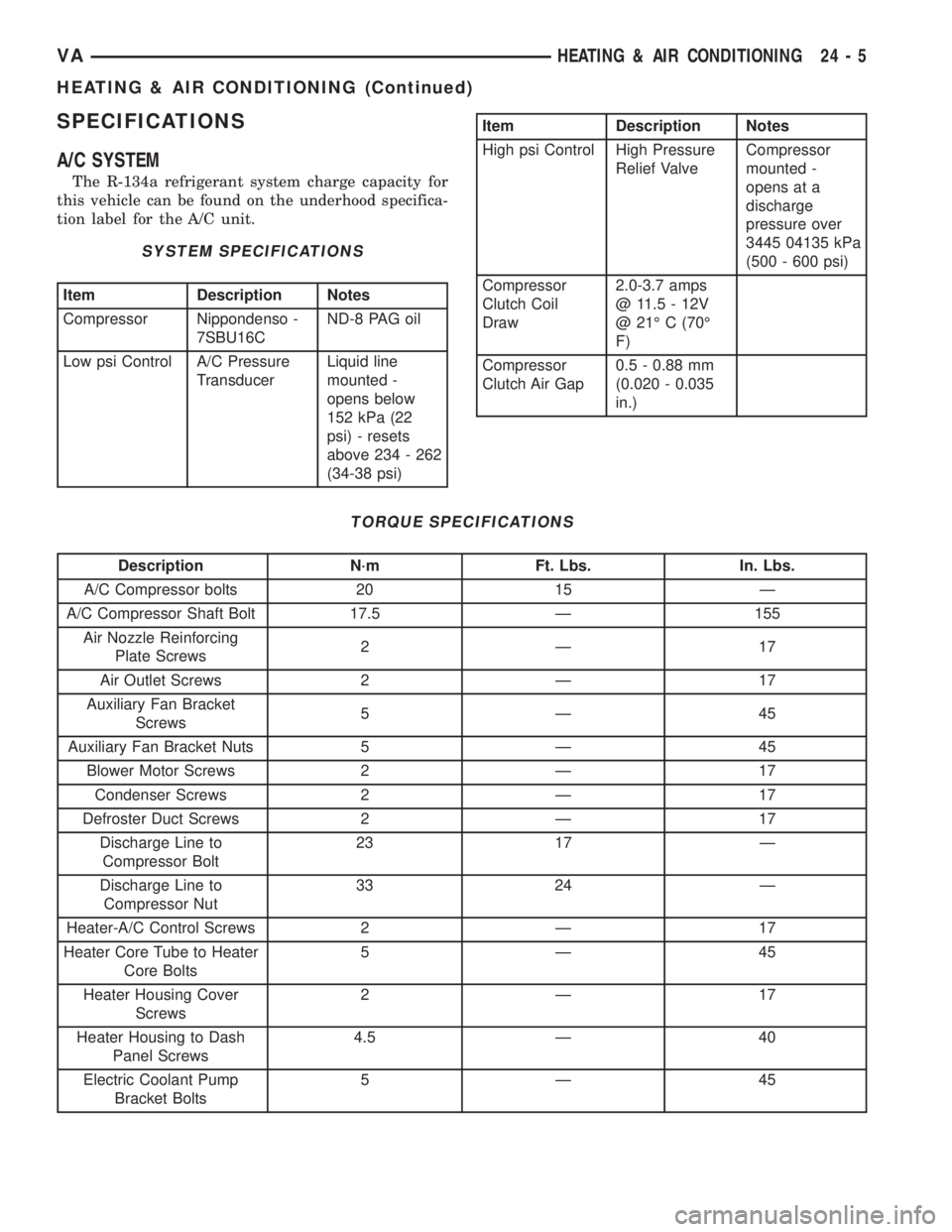
A/C SYSTEM
The R-134a refrigerant system charge capacity for
this vehicle can be found on the underhood specifica-
tion label for the A/C unit.
SYSTEM SPECIFICATIONS
Item Description Notes
Compressor Nippondenso -
7SBU16CND-8 PAG oil
Low psi Control A/C Pressure
TransducerLiquid line
mounted -
opens below
152 kPa (22
psi) - resets
above 234 - 262
(34-38 psi)
Item Description Notes
High psi Control High Pressure
Relief ValveCompressor
mounted -
opens at a
discharge
pressure over
3445 04135 kPa
(500 - 600 psi)
Compressor
Clutch Coil
Draw2.0-3.7 amps
@ 11.5 - 12V
@ 21É C (70É
F)
Compressor
Clutch Air Gap0.5 - 0.88 mm
(0.020 - 0.035
in.)
TORQUE SPECIFICATIONS
Description N´m Ft. Lbs. In. Lbs.
A/C Compressor bolts 20 15 Ð
A/C Compressor Shaft Bolt 17.5 Ð 155
Air Nozzle Reinforcing
Plate Screws2Ð 17
Air Outlet Screws 2 Ð 17
Auxiliary Fan Bracket
Screws5Ð 45
Auxiliary Fan Bracket Nuts 5 Ð 45
Blower Motor Screws 2 Ð 17
Condenser Screws 2 Ð 17
Defroster Duct Screws 2 Ð 17
Discharge Line to
Compressor Bolt23 17 Ð
Discharge Line to
Compressor Nut33 24 Ð
Heater-A/C Control Screws 2 Ð 17
Heater Core Tube to Heater
Core Bolts5Ð 45
Heater Housing Cover
Screws2Ð 17
Heater Housing to Dash
Panel Screws4.5 Ð 40
Electric Coolant Pump
Bracket Bolts5Ð 45
VAHEATING & AIR CONDITIONING 24 - 5
HEATING & AIR CONDITIONING (Continued)
Page 1171 of 1232
PLUMBING
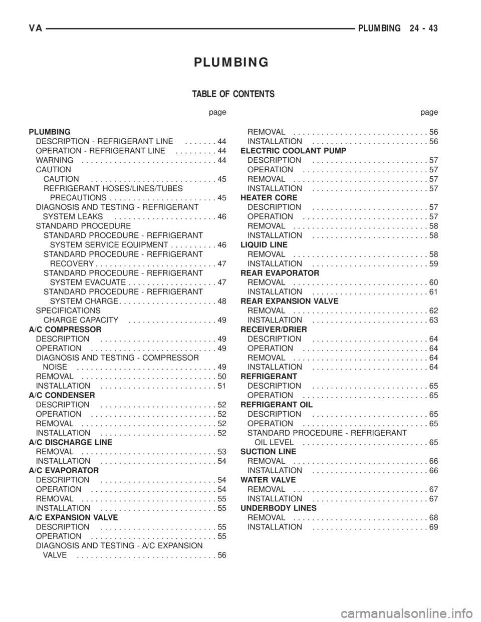
TABLE OF CONTENTS
page page
PLUMBING
DESCRIPTION - REFRIGERANT LINE.......44
OPERATION - REFRIGERANT LINE.........44
WARNING.............................44
CAUTION
CAUTION...........................45
REFRIGERANT HOSES/LINES/TUBES
PRECAUTIONS.......................45
DIAGNOSIS AND TESTING - REFRIGERANT
SYSTEM LEAKS......................46
STANDARD PROCEDURE
STANDARD PROCEDURE - REFRIGERANT
SYSTEM SERVICE EQUIPMENT..........46
STANDARD PROCEDURE - REFRIGERANT
RECOVERY..........................47
STANDARD PROCEDURE - REFRIGERANT
SYSTEM EVACUATE...................47
STANDARD PROCEDURE - REFRIGERANT
SYSTEM CHARGE.....................48
SPECIFICATIONS
CHARGE CAPACITY...................49
A/C COMPRESSOR
DESCRIPTION.........................49
OPERATION...........................49
DIAGNOSIS AND TESTING - COMPRESSOR
NOISE..............................49
REMOVAL.............................50
INSTALLATION.........................51
A/C CONDENSER
DESCRIPTION.........................52
OPERATION...........................52
REMOVAL.............................52
INSTALLATION.........................52
A/C DISCHARGE LINE
REMOVAL.............................53
INSTALLATION.........................54
A/C EVAPORATOR
DESCRIPTION.........................54
OPERATION...........................54
REMOVAL.............................55
INSTALLATION.........................55
A/C EXPANSION VALVE
DESCRIPTION.........................55
OPERATION...........................55
DIAGNOSIS AND TESTING - A/C EXPANSION
VALVE ..............................56REMOVAL.............................56
INSTALLATION.........................56
ELECTRIC COOLANT PUMP
DESCRIPTION.........................57
OPERATION...........................57
REMOVAL.............................57
INSTALLATION.........................57
HEATER CORE
DESCRIPTION.........................57
OPERATION...........................57
REMOVAL.............................58
INSTALLATION.........................58
LIQUID LINE
REMOVAL.............................58
INSTALLATION.........................59
REAR EVAPORATOR
REMOVAL.............................60
INSTALLATION.........................61
REAR EXPANSION VALVE
REMOVAL.............................62
INSTALLATION.........................63
RECEIVER/DRIER
DESCRIPTION.........................64
OPERATION...........................64
REMOVAL.............................64
INSTALLATION.........................64
REFRIGERANT
DESCRIPTION.........................65
OPERATION...........................65
REFRIGERANT OIL
DESCRIPTION.........................65
OPERATION...........................65
STANDARD PROCEDURE - REFRIGERANT
OIL LEVEL...........................65
SUCTION LINE
REMOVAL.............................66
INSTALLATION.........................66
WAT E R VA LV E
REMOVAL.............................67
INSTALLATION.........................67
UNDERBODY LINES
REMOVAL.............................68
INSTALLATION.........................69
VAPLUMBING 24 - 43
Page 1172 of 1232
PLUMBING
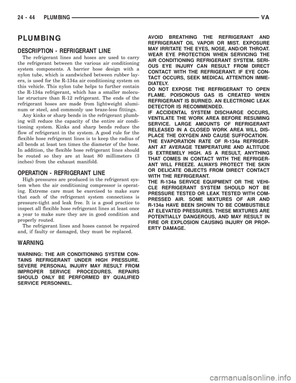
DESCRIPTION - REFRIGERANT LINE
The refrigerant lines and hoses are used to carry
the refrigerant between the various air conditioning
system components. A barrier hose design with a
nylon tube, which is sandwiched between rubber lay-
ers, is used for the R-134a air conditioning system on
this vehicle. This nylon tube helps to further contain
the R-134a refrigerant, which has a smaller molecu-
lar structure than R-12 refrigerant. The ends of the
refrigerant hoses are made from lightweight alumi-
num or steel, and commonly use braze-less fittings.
Any kinks or sharp bends in the refrigerant plumb-
ing will reduce the capacity of the entire air condi-
tioning system. Kinks and sharp bends reduce the
flow of refrigerant in the system. A good rule for the
flexible hose refrigerant lines is to keep the radius of
all bends at least ten times the diameter of the hose.
In addition, the flexible hose refrigerant lines should
be routed so they are at least 80 millimeters (3
inches) from the exhaust manifold.
OPERATION - REFRIGERANT LINE
High pressures are produced in the refrigerant sys-
tem when the air conditioning compressor is operat-
ing. Extreme care must be exercised to make sure
that each of the refrigerant system connections is
pressure-tight and leak free. It is a good practice to
inspect all flexible hose refrigerant lines at least once
a year to make sure they are in good condition and
properly routed.
The refrigerant lines and hoses cannot be repaired
and, if faulty or damaged, they must be replaced.
WARNING
WARNING: THE AIR CONDITIONING SYSTEM CON-
TAINS REFRIGERANT UNDER HIGH PRESSURE.
SEVERE PERSONAL INJURY MAY RESULT FROM
IMPROPER SERVICE PROCEDURES. REPAIRS
SHOULD ONLY BE PERFORMED BY QUALIFIED
SERVICE PERSONNEL.AVOID BREATHING THE REFRIGERANT AND
REFRIGERANT OIL VAPOR OR MIST. EXPOSURE
MAY IRRITATE THE EYES, NOSE, AND/OR THROAT.
WEAR EYE PROTECTION WHEN SERVICING THE
AIR CONDITIONING REFRIGERANT SYSTEM. SERI-
OUS EYE INJURY CAN RESULT FROM DIRECT
CONTACT WITH THE REFRIGERANT. IF EYE CON-
TACT OCCURS, SEEK MEDICAL ATTENTION IMME-
DIATELY.
DO NOT EXPOSE THE REFRIGERANT TO OPEN
FLAME. POISONOUS GAS IS CREATED WHEN
REFRIGERANT IS BURNED. AN ELECTRONIC LEAK
DETECTOR IS RECOMMENDED.
IF ACCIDENTAL SYSTEM DISCHARGE OCCURS,
VENTILATE THE WORK AREA BEFORE RESUMING
SERVICE. LARGE AMOUNTS OF REFRIGERANT
RELEASED IN A CLOSED WORK AREA WILL DIS-
PLACE THE OXYGEN AND CAUSE SUFFOCATION.
THE EVAPORATION RATE OF R-134a REFRIGER-
ANT AT AVERAGE TEMPERATURE AND ALTITUDE
IS EXTREMELY HIGH. AS A RESULT, ANYTHING
THAT COMES IN CONTACT WITH THE REFRIGER-
ANT WILL FREEZE. ALWAYS PROTECT THE SKIN
OR DELICATE OBJECTS FROM DIRECT CONTACT
WITH THE REFRIGERANT.
THE R-134a SERVICE EQUIPMENT OR THE VEHI-
CLE REFRIGERANT SYSTEM SHOULD NOT BE
PRESSURE TESTED OR LEAK TESTED WITH COM-
PRESSED AIR. SOME MIXTURES OF AIR AND
R-134a HAVE BEEN SHOWN TO BE COMBUSTIBLE
AT ELEVATED PRESSURES. THESE MIXTURES ARE
POTENTIALLY DANGEROUS, AND MAY RESULT IN
FIRE OR EXPLOSION CAUSING INJURY OR PROP-
ERTY DAMAGE.
24 - 44 PLUMBINGVA
Page 1173 of 1232
CAUTION
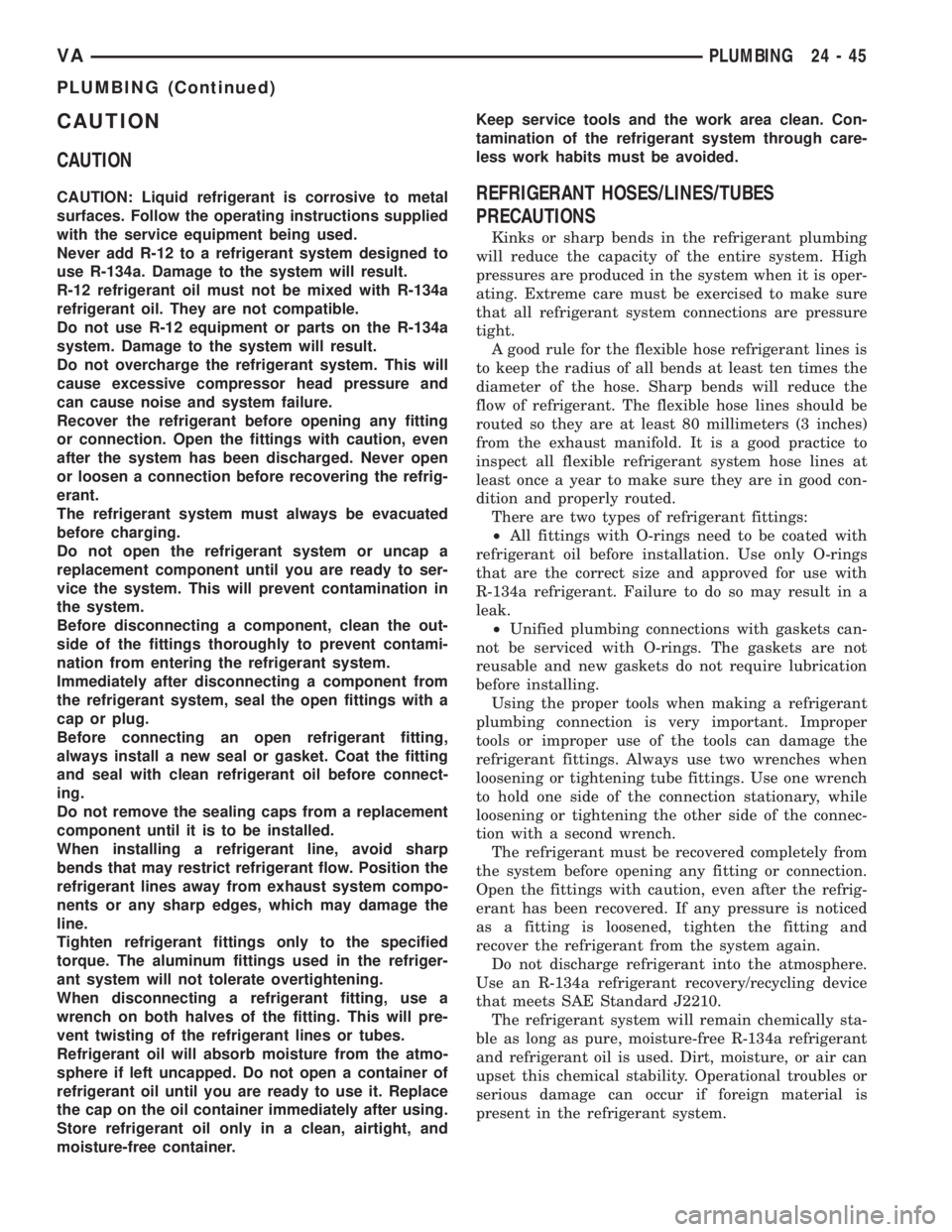
CAUTION
CAUTION: Liquid refrigerant is corrosive to metal
surfaces. Follow the operating instructions supplied
with the service equipment being used.
Never add R-12 to a refrigerant system designed to
use R-134a. Damage to the system will result.
R-12 refrigerant oil must not be mixed with R-134a
refrigerant oil. They are not compatible.
Do not use R-12 equipment or parts on the R-134a
system. Damage to the system will result.
Do not overcharge the refrigerant system. This will
cause excessive compressor head pressure and
can cause noise and system failure.
Recover the refrigerant before opening any fitting
or connection. Open the fittings with caution, even
after the system has been discharged. Never open
or loosen a connection before recovering the refrig-
erant.
The refrigerant system must always be evacuated
before charging.
Do not open the refrigerant system or uncap a
replacement component until you are ready to ser-
vice the system. This will prevent contamination in
the system.
Before disconnecting a component, clean the out-
side of the fittings thoroughly to prevent contami-
nation from entering the refrigerant system.
Immediately after disconnecting a component from
the refrigerant system, seal the open fittings with a
cap or plug.
Before connecting an open refrigerant fitting,
always install a new seal or gasket. Coat the fitting
and seal with clean refrigerant oil before connect-
ing.
Do not remove the sealing caps from a replacement
component until it is to be installed.
When installing a refrigerant line, avoid sharp
bends that may restrict refrigerant flow. Position the
refrigerant lines away from exhaust system compo-
nents or any sharp edges, which may damage the
line.
Tighten refrigerant fittings only to the specified
torque. The aluminum fittings used in the refriger-
ant system will not tolerate overtightening.
When disconnecting a refrigerant fitting, use a
wrench on both halves of the fitting. This will pre-
vent twisting of the refrigerant lines or tubes.
Refrigerant oil will absorb moisture from the atmo-
sphere if left uncapped. Do not open a container of
refrigerant oil until you are ready to use it. Replace
the cap on the oil container immediately after using.
Store refrigerant oil only in a clean, airtight, and
moisture-free container.Keep service tools and the work area clean. Con-
tamination of the refrigerant system through care-
less work habits must be avoided.REFRIGERANT HOSES/LINES/TUBES
PRECAUTIONS
Kinks or sharp bends in the refrigerant plumbing
will reduce the capacity of the entire system. High
pressures are produced in the system when it is oper-
ating. Extreme care must be exercised to make sure
that all refrigerant system connections are pressure
tight.
A good rule for the flexible hose refrigerant lines is
to keep the radius of all bends at least ten times the
diameter of the hose. Sharp bends will reduce the
flow of refrigerant. The flexible hose lines should be
routed so they are at least 80 millimeters (3 inches)
from the exhaust manifold. It is a good practice to
inspect all flexible refrigerant system hose lines at
least once a year to make sure they are in good con-
dition and properly routed.
There are two types of refrigerant fittings:
²All fittings with O-rings need to be coated with
refrigerant oil before installation. Use only O-rings
that are the correct size and approved for use with
R-134a refrigerant. Failure to do so may result in a
leak.
²Unified plumbing connections with gaskets can-
not be serviced with O-rings. The gaskets are not
reusable and new gaskets do not require lubrication
before installing.
Using the proper tools when making a refrigerant
plumbing connection is very important. Improper
tools or improper use of the tools can damage the
refrigerant fittings. Always use two wrenches when
loosening or tightening tube fittings. Use one wrench
to hold one side of the connection stationary, while
loosening or tightening the other side of the connec-
tion with a second wrench.
The refrigerant must be recovered completely from
the system before opening any fitting or connection.
Open the fittings with caution, even after the refrig-
erant has been recovered. If any pressure is noticed
as a fitting is loosened, tighten the fitting and
recover the refrigerant from the system again.
Do not discharge refrigerant into the atmosphere.
Use an R-134a refrigerant recovery/recycling device
that meets SAE Standard J2210.
The refrigerant system will remain chemically sta-
ble as long as pure, moisture-free R-134a refrigerant
and refrigerant oil is used. Dirt, moisture, or air can
upset this chemical stability. Operational troubles or
serious damage can occur if foreign material is
present in the refrigerant system.
VAPLUMBING 24 - 45
PLUMBING (Continued)