2005 MERCEDES-BENZ SPRINTER torque
[x] Cancel search: torquePage 3 of 1232
INTRODUCTION
TABLE OF CONTENTS
page page
VEHICLE IDENTIFICATION NUMBER
DESCRIPTION..........................1
INTERNATIONAL SYMBOLS
DESCRIPTION..........................2
FASTENER IDENTIFICATION
DESCRIPTION..........................2
FASTENER USAGE
DESCRIPTION - FASTENER USAGE.........5THREADED HOLE REPAIR
DESCRIPTION - THREADED HOLE REPAIR....5
METRIC SYSTEM
DESCRIPTION..........................5
TORQUE REFERENCES
DESCRIPTION..........................7
VEHICLE IDENTIFICATION
NUMBER
DESCRIPTION
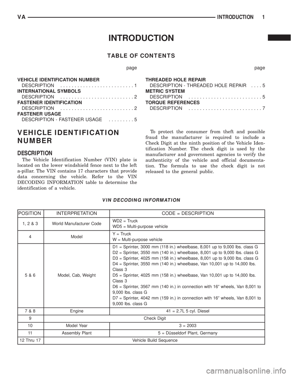
The Vehicle Identification Number (VIN) plate is
located on the lower windshield fence next to the left
a-pillar. The VIN contains 17 characters that provide
data concerning the vehicle. Refer to the VIN
DECODING INFORMATION table to determine the
identification of a vehicle.To protect the consumer from theft and possible
fraud the manufacturer is required to include a
Check Digit at the ninth position of the Vehicle Iden-
tification Number. The check digit is used by the
manufacturer and government agencies to verify the
authenticity of the vehicle and official documenta-
tion. The formula to use the check digit is not
released to the general public.
VIN DECODING INFORMATION
POSITION INTERPRETATION CODE = DESCRIPTION
1,2&3 World Manufacturer CodeWD2 = Truck
WD5 = Multi-purpose vehicle
4 ModelY = Truck
W = Multi-purpose vehicle
5 & 6 Model, Cab, WeightD1 = Sprinter, 3000 mm (118 in.) wheelbase, 8,001 up to 9,000 lbs. class G
D2 = Sprinter, 3550 mm (140 in.) wheelbase, 8,001 up to 9,000 lbs. class G
D3 = Sprinter, 4025 mm (158 in.) wheelbase, 8,001 up to 9,000 lbs. class G
D4 = Sprinter, 3550 mm (140 in.) wheelbase, Van 10,001 up to 14,000 lbs.
Class 3
D5 = Sprinter, 4025 mm (158 in.) wheelbase, Van 10,001 up to 14,000 lbs.
Class 3
D6 = Sprinter, 3567 mm (140 in.) in connection with 169wheels, Van 8,001 to
9,000 lbs. class G
D7 = Sprinter, 4042 mm (159 in.) in connection with 169wheels, Van 8,001 to
9,000 lbs. class G
7 & 8 Engine 41 = 2.7L 5 cyl. Diesel
9 Check Digit
10 Model Year 3 = 2003
11 Assembly Plant 5 = Dîsseldorf Plant, Germany
12 Thru 17 Vehicle Build Sequence
VAINTRODUCTION 1
Page 7 of 1232
FASTENER USAGE
DESCRIPTION - FASTENER USAGE
WARNING: USE OF AN INCORRECT FASTENER
MAY RESULT IN COMPONENT DAMAGE OR PER-
SONAL INJURY.
Fasteners and torque specifications references in
this Service Manual are identified in metric and SAE
format.
During any maintenance or repair procedures, it is
important to salvage all fasteners (nuts, bolts, etc.)
for reassembly. If the fastener is not salvageable, a
fastener of equivalent specification must be used.
THREADED HOLE REPAIR
DESCRIPTION - THREADED HOLE REPAIR
Most stripped threaded holes can be repaired using
a Helicoilt. Follow the vehicle or Helicoiltrecommen-
dations for application and repair procedures.
METRIC SYSTEM
DESCRIPTION
The metric system is based on quantities of one,
ten, one hundred, one thousand and one million.
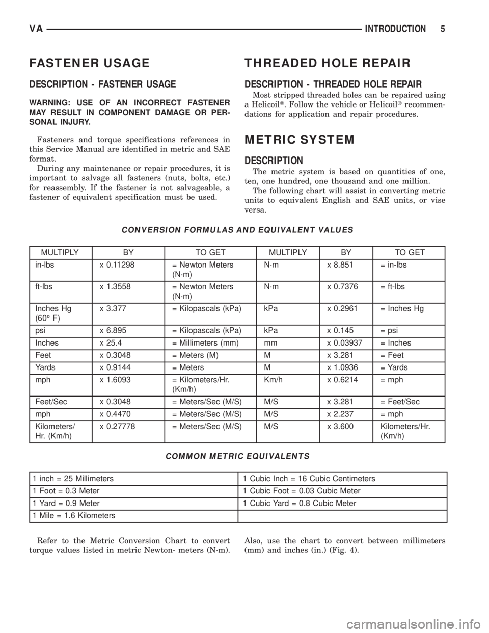
The following chart will assist in converting metric
units to equivalent English and SAE units, or vise
versa.
CONVERSION FORMULAS AND EQUIVALENT VALUES
MULTIPLY BY TO GET MULTIPLY BY TO GET
in-lbs x 0.11298 = Newton Meters
(N´m)N´m x 8.851 = in-lbs
ft-lbs x 1.3558 = Newton Meters
(N´m)N´m x 0.7376 = ft-lbs
Inches Hg
(60É F)x 3.377 = Kilopascals (kPa) kPa x 0.2961 = Inches Hg
psi x 6.895 = Kilopascals (kPa) kPa x 0.145 = psi
Inches x 25.4 = Millimeters (mm) mm x 0.03937 = Inches
Feet x 0.3048 = Meters (M) M x 3.281 = Feet
Yards x 0.9144 = Meters M x 1.0936 = Yards
mph x 1.6093 = Kilometers/Hr.
(Km/h)Km/h x 0.6214 = mph
Feet/Sec x 0.3048 = Meters/Sec (M/S) M/S x 3.281 = Feet/Sec
mph x 0.4470 = Meters/Sec (M/S) M/S x 2.237 = mph
Kilometers/
Hr. (Km/h)x 0.27778 = Meters/Sec (M/S) M/S x 3.600 Kilometers/Hr.
(Km/h)
COMMON METRIC EQUIVALENTS
1 inch = 25 Millimeters 1 Cubic Inch = 16 Cubic Centimeters
1 Foot = 0.3 Meter 1 Cubic Foot = 0.03 Cubic Meter
1 Yard = 0.9 Meter 1 Cubic Yard = 0.8 Cubic Meter
1 Mile = 1.6 Kilometers
Refer to the Metric Conversion Chart to convert
torque values listed in metric Newton- meters (N´m).Also, use the chart to convert between millimeters
(mm) and inches (in.) (Fig. 4).
VAINTRODUCTION 5
Page 9 of 1232
TORQUE REFERENCES
DESCRIPTION
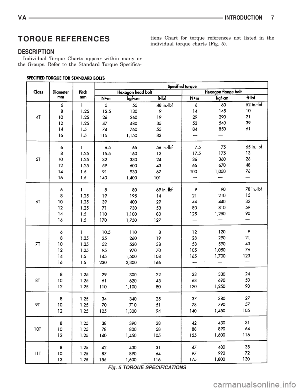
Individual Torque Charts appear within many or
the Groups. Refer to the Standard Torque Specifica-tions Chart for torque references not listed in the
individual torque charts (Fig. 5).
Fig. 5 TORQUE SPECIFICATIONS
VAINTRODUCTION 7
Page 21 of 1232
SUSPENSION
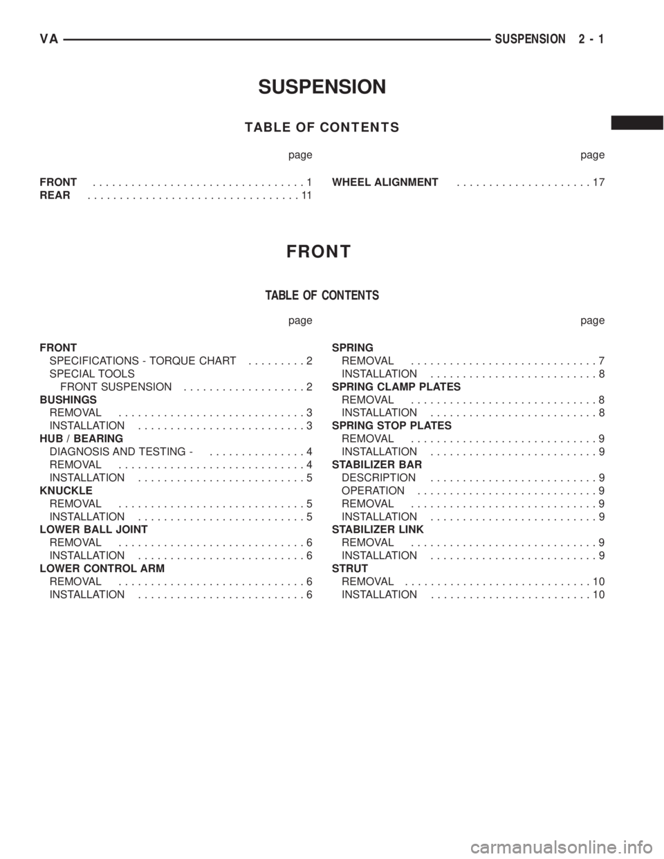
TABLE OF CONTENTS
page page
FRONT.................................1
REAR.................................11WHEEL ALIGNMENT.....................17
FRONT
TABLE OF CONTENTS
page page
FRONT
SPECIFICATIONS - TORQUE CHART.........2
SPECIAL TOOLS
FRONT SUSPENSION...................2
BUSHINGS
REMOVAL.............................3
INSTALLATION..........................3
HUB / BEARING
DIAGNOSIS AND TESTING -...............4
REMOVAL.............................4
INSTALLATION..........................5
KNUCKLE
REMOVAL.............................5
INSTALLATION..........................5
LOWER BALL JOINT
REMOVAL.............................6
INSTALLATION..........................6
LOWER CONTROL ARM
REMOVAL.............................6
INSTALLATION..........................6SPRING
REMOVAL.............................7
INSTALLATION..........................8
SPRING CLAMP PLATES
REMOVAL.............................8
INSTALLATION..........................8
SPRING STOP PLATES
REMOVAL.............................9
INSTALLATION..........................9
STABILIZER BAR
DESCRIPTION..........................9
OPERATION............................9
REMOVAL.............................9
INSTALLATION..........................9
STABILIZER LINK
REMOVAL.............................9
INSTALLATION..........................9
STRUT
REMOVAL.............................10
INSTALLATION.........................10
VASUSPENSION 2 - 1
Page 22 of 1232
FRONT
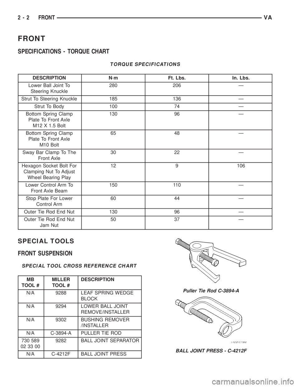
SPECIFICATIONS - TORQUE CHART
TORQUE SPECIFICATIONS
DESCRIPTION N´m Ft. Lbs. In. Lbs.
Lower Ball Joint To
Steering Knuckle280 206 Ð
Strut To Steering Knuckle 185 136 Ð
Strut To Body 100 74 Ð
Bottom Spring Clamp
Plate To Front Axle
M12 X 1.5 Bolt130 96 Ð
Bottom Spring Clamp
Plate To Front Axle
M10 Bolt65 48 Ð
Sway Bar Clamp To The
Front Axle30 22 Ð
Hexagon Socket Bolt For
Clamping Nut To Adjust
Wheel Bearing Play12 9 106
Lower Control Arm To
Front Axle Beam150 110 Ð
Stop Plate For Lower
Control Arm60 44 Ð
Outer Tie Rod End Nut 130 96 Ð
Outer Tie Rod End Nut
Jam Nut50 37 Ð
SPECIAL TOOLS
FRONT SUSPENSION
SPECIAL TOOL CROSS REFERENCE CHART
MB
TOOL #MILLER
TOOL #DESCRIPTION
N/A 9288 LEAF SPRING WEDGE
BLOCK
N/A 9294 LOWER BALL JOINT
REMOVE/INSTALLER
N/A 9302 BUSHING REMOVER
/INSTALLER
N/A C-3894-A PULLER TIE ROD
730 589
02 33 009282 BALL JOINT SEPARATOR
N/A C-4212F BALL JOINT PRESS
Puller Tie Rod C-3894-A
BALL JOINT PRESS - C-4212F
2 - 2 FRONTVA
Page 31 of 1232
REAR
TABLE OF CONTENTS
page page
REAR
DESCRIPTION.........................11
DIAGNOSIS AND TESTING - SPRING AND
SHOCK.............................11
SPECIFICATIONS - TORQUE CHART........12
SHOCK
DIAGNOSIS AND TESTING - SHOCK........13
REMOVAL.............................13
INSTALLATION.........................13
SPRING
DESCRIPTION.........................14
OPERATION...........................14
REMOVAL
REMOVAL - (SRW)....................14REMOVAL - (DRW)....................14
INSTALLATION
INSTALLATION - (SRW).................14
INSTALLATION - (DRW).................15
SPRING SHACKLE
REMOVAL.............................15
INSTALLATION.........................15
STABILIZER BAR
REMOVAL.............................15
INSTALLATION.........................15
STABILIZER LINK
REMOVAL.............................16
INSTALLATION.........................16
REAR
DESCRIPTION
The rear suspension is comprised of:
²Shock Absorbers
²Jounce Bumpers
²Stabilizer Bar
²Leaf Springs
²Drive Axle
CAUTION: A vehicle should always be loaded so
the vehicle weight center-line is located immedi-
ately forward of the rear axle. Correct vehicle load-
ing provides proper front tire-to-road contact. This
results in maximum vehicle handling stability and
safety. Incorrect vehicle weight distribution can
cause excessive tire tread wear, spring fatigue or
failure, and erratic steering.
CAUTION: Suspension components with rubber/ure-
thane bushings (except stabilizer bar) should be
tightened with the vehicle at normal ride height. It is
important to have the springs supporting the weight
of the vehicle when the fasteners are torqued. If
springs are not at their normal ride position, vehicle
ride comfort could be affected and premature bush-
ing wear may occur.
DIAGNOSIS AND TESTING - SPRING AND
SHOCK
A knocking or rattling noise from a shock absorber
may be caused by movement between mounting
bushings and metal brackets or attaching compo-
nents. These noises can usually be stopped by tight-
ening the attaching nuts. If the noise persists,
inspect for damaged and worn bushings, and attach-
ing components. Repair as necessary if any of these
conditions exist.
A squeaking noise from the shock absorber may be
caused by the hydraulic valving and may be intermit-
tent. This condition is not repairable and the shock
absorber must be replaced.
The shock absorbers are not refillable or adjust-
able. If a malfunction occurs, the shock absorber
must be replaced. To test a shock absorber, hold it in
an upright position and force the piston in and out of
the cylinder four or five times. The action throughout
each stroke should be smooth and even.
The spring eye and shock absorber bushings do not
require any type of lubrication. Do not attempt to
stop spring bushing noise by lubricating them.
Grease and mineral oil-base lubricants will deterio-
rate the bushing rubber.
If the vehicle is used for severe, off-road operation,
the springs should be examined periodically. Check
for broken and shifted leafs, loose and missing clips,
and broken center bolts. Refer to Spring and Shock
Absorber Diagnosis chart for additional information.
VAREAR 2 - 11
Page 32 of 1232
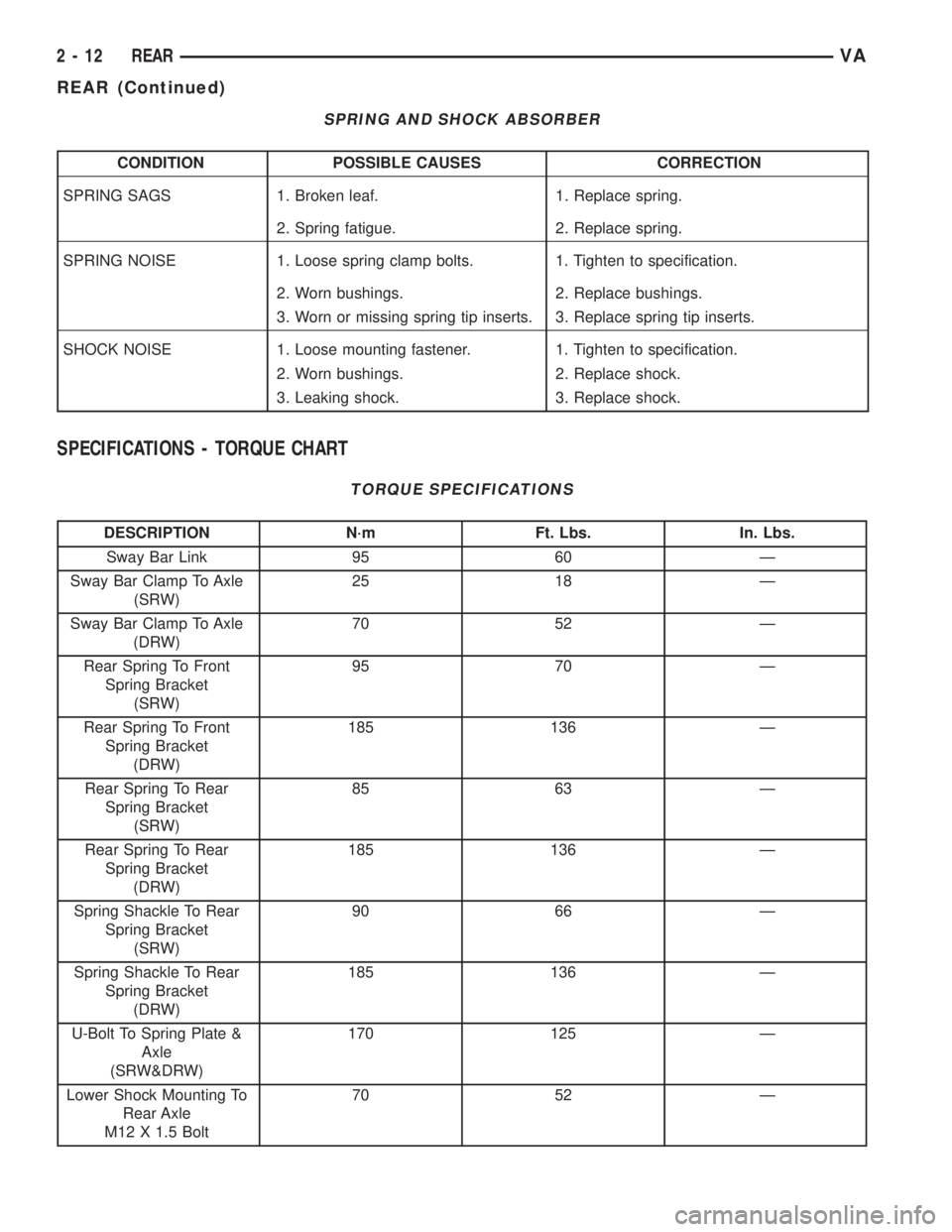
SPRING AND SHOCK ABSORBER
CONDITION POSSIBLE CAUSES CORRECTION
SPRING SAGS 1. Broken leaf. 1. Replace spring.
2. Spring fatigue. 2. Replace spring.
SPRING NOISE 1. Loose spring clamp bolts. 1. Tighten to specification.
2. Worn bushings. 2. Replace bushings.
3. Worn or missing spring tip inserts. 3. Replace spring tip inserts.
SHOCK NOISE 1. Loose mounting fastener. 1. Tighten to specification.
2. Worn bushings. 2. Replace shock.
3. Leaking shock. 3. Replace shock.
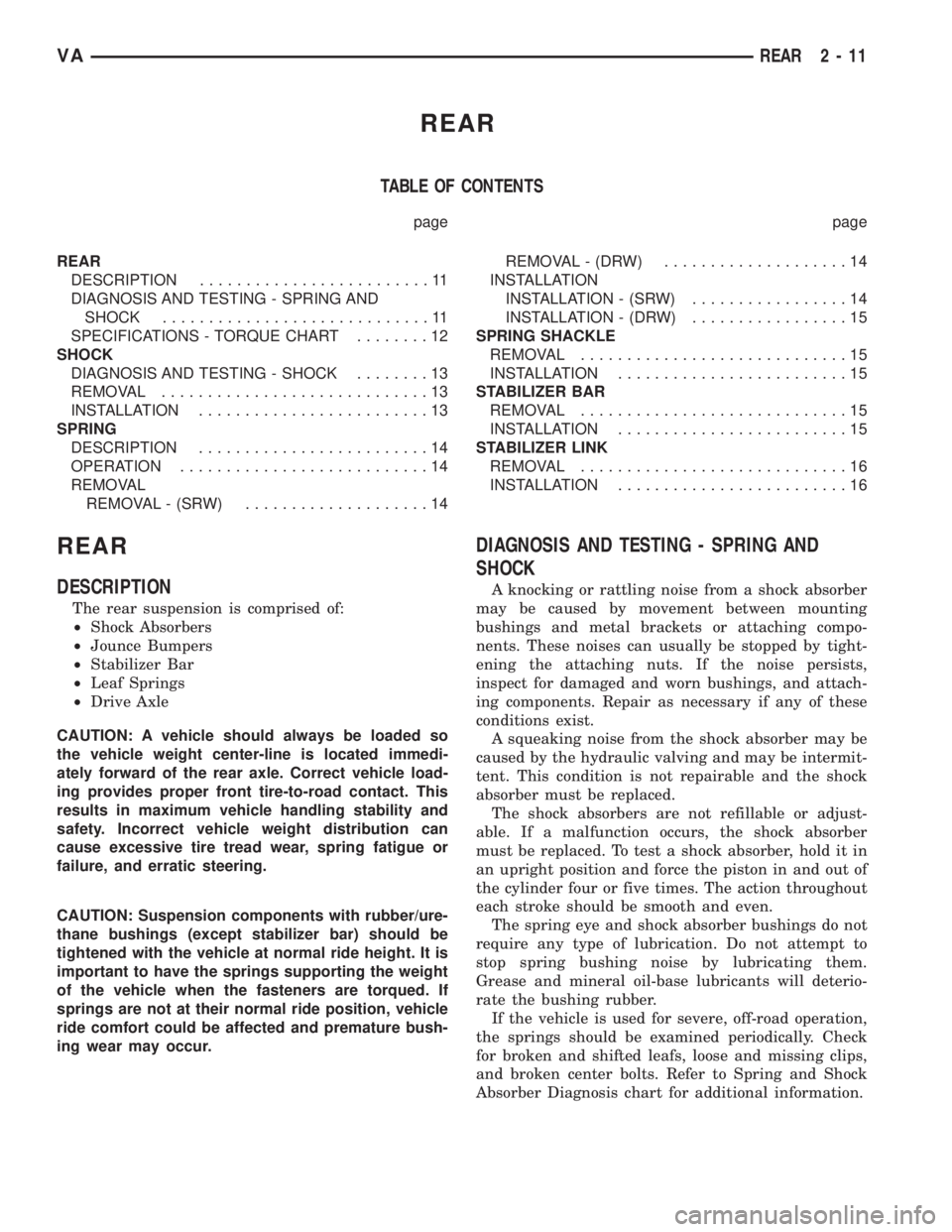
SPECIFICATIONS - TORQUE CHART
TORQUE SPECIFICATIONS
DESCRIPTION N´m Ft. Lbs. In. Lbs.
Sway Bar Link 95 60 Ð
Sway Bar Clamp To Axle
(SRW)25 18 Ð
Sway Bar Clamp To Axle
(DRW)70 52 Ð
Rear Spring To Front
Spring Bracket
(SRW)95 70 Ð
Rear Spring To Front
Spring Bracket
(DRW)185 136 Ð
Rear Spring To Rear
Spring Bracket
(SRW)85 63 Ð
Rear Spring To Rear
Spring Bracket
(DRW)185 136 Ð
Spring Shackle To Rear
Spring Bracket
(SRW)90 66 Ð
Spring Shackle To Rear
Spring Bracket
(DRW)185 136 Ð
U-Bolt To Spring Plate &
Axle
(SRW&DRW)170 125 Ð
Lower Shock Mounting To
Rear Axle
M12 X 1.5 Bolt70 52 Ð
2 - 12 REARVA
REAR (Continued)
Page 37 of 1232
WHEEL ALIGNMENT
TABLE OF CONTENTS
page page
WHEEL ALIGNMENT
DESCRIPTION.........................17
DIAGNOSIS AND TESTING - PRE-ALIGNMENT
INSPECTION.........................17STANDARD PROCEDURE - TOE
ADJUSTMENT........................19
SPECIFICATIONS.......................19
WHEEL ALIGNMENT
DESCRIPTION
NOTE: Camber and Caster are not adjustable on
this vehicle. (TOE ONLY).
NOTE: Suspension components with rubber/ure-
thane bushings should be tightened with the vehi-
cle at normal ride height. It is important to have the
springs supporting the weight of the vehicle when
the fasteners are torqued. If springs are not at their
normal ride position, vehicle ride comfort could be
affected and premature bushing wear may occur.
Wheel alignment involves the correct positioning of
the wheels in relation to the vehicle. The positioning
is accomplished through suspension and steering
linkage adjustments. An alignment is considered
essential for efficient steering, good directional stabil-
ity and to minimize tire wear. The most important
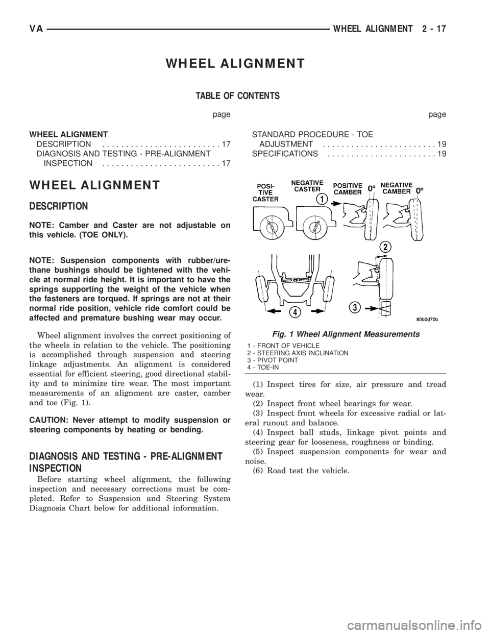
measurements of an alignment are caster, camber
and toe (Fig. 1).
CAUTION: Never attempt to modify suspension or
steering components by heating or bending.
DIAGNOSIS AND TESTING - PRE-ALIGNMENT
INSPECTION
Before starting wheel alignment, the following
inspection and necessary corrections must be com-
pleted. Refer to Suspension and Steering System
Diagnosis Chart below for additional information.(1) Inspect tires for size, air pressure and tread
wear.
(2) Inspect front wheel bearings for wear.
(3) Inspect front wheels for excessive radial or lat-
eral runout and balance.
(4) Inspect ball studs, linkage pivot points and
steering gear for looseness, roughness or binding.
(5) Inspect suspension components for wear and
noise.
(6) Road test the vehicle.
Fig. 1 Wheel Alignment Measurements
1 - FRONT OF VEHICLE
2 - STEERING AXIS INCLINATION
3 - PIVOT POINT
4 - TOE-IN
VAWHEEL ALIGNMENT 2 - 17