2005 MERCEDES-BENZ SPRINTER reset
[x] Cancel search: resetPage 18 of 1232
MAINTENANCE - WITH ASSYST MAINTENANCE
COMPUTER
ASSYST provides information on the best possible
timing for maintenance work.
NOTE: The engine manufacturer strongly recom-
mends the use of synthetic engine oils, such as
TMobil 1 SAE 0W-40.
When the next maintenance service is due, this
will be indicated in the multi-function display with
the wrench icon symbol displayed in km/miles or
days.
²One wrench icon showing indicates Oil Service
is necessary.
²Two wrench icons showing indicates Mainte-
nance Service is necessary ± displayed in km/miles or
days.
If the display shows the number of days, a clock
symbol will also appear in the multi-function display.
You should have the maintenance performed
within the stated period/distance.
The service indicator should be reset after an oil
service and/or maintenance service has been per-
formed.
REGULAR CHECK-UPS
To maintain the safe operation of the vehicle, it is
recommended that the following tasks be performed
on a regular basis (i.e. weekly or whenever the vehi-
cle is refueled). Check:
²Engine oil level
²Brake system, clutch mechanism ± fluid level
²Battery ± acid level
²Windshield washer system and headlamp clean-
ing system ± fluid level
²Mechanical assemblies (e. g. engine, transmis-
sion, etc.) ± check for leaks
²Condition of tires and tires pressures
²All exterior lights
SPECIAL MAINTENANCE REQUIREMENTS
If bodies built by manufacturers other than
DaimlerChrysler Corporation are fitted to the vehi-
cle, the maintenance requirements and lubrication
intervals specified by the body manufacturer must be
adhered to, in addition to all standard maintenance
requirements.
Brake Fluid
Only use brake fluids approved by the manufac-
turer (DOT 4 plus).
Coolant
Corrosion inhibitor/antifreeze concentration in the
coolant should be checked before the onset of winter
(once year in countries with high prevailing temper-
atures).Replace the coolant every five years or 100,000
miles.
Dust Filter for Heating/Ventilation Replace-
ment
The dust filter and the tailgate interior filter are to
be renewed during routine maintenance service. If
operating conditions are dusty, these filters should be
renewed more frequently.
ENGINE OIL CHANGE AND FILTER REPLACEMENT
At the minimum, change the engine oil and oil fil-
ter once a year ± even if the vehicle mileage per year
is extremely low. For standard oil service schedules
refer to the chapter oil service and maintenance ser-
vice.
Once a Year
Select the viscosity of the engine oil (SAE classes)
according to the outside air temperature.
Only use engine oil approved by DaimlerChrysler
Corporation if following the ASSYST system guide-
lines.
If the fuel used has a sulphur content exceeding
0.05% by weight, the service intervals should be split
in half.
SCOPE OF WORK FOR MAINTENANCE SERVICE
Oil Service
²Engine:
Oil change and filter replacement
Check fluid levels of the following system,
refill as necessary.
²If fluid is lost, trace and eliminate cause ± as a
separate order.
²Power-assisted steering
Lubrication work:
²Trailer tow hitch (original equipment)
Maintenance
²ASSYST maintenance computer reset
Function check
²Signalling system, warning and indicator lamps
²Headlamps, exterior lighting
²Windshield wipers, windshield washer system
Check for leaks and damage.
²Check for abrasion points and ensure that lines
are correctly routed!
²All lines and hoses, sensor cables
²Rubber boots on front axle drive shafts, rubber
boots on front axle suspension ball joints, shock
absorbers
Check fluid levels for the following systems,
correct as necessary.
NOTE: Should there be a loss of fluid which cannot
be explained by regular use, trace and eliminate the
cause.
0 - 8 LUBRICATION & MAINTENANCEVA
MAINTENANCE SCHEDULES (Continued)
Page 128 of 1232
(clutch or brake). Fill time adaptation is the ability of
the TCM to modify the time it takes to fill the shift
member by applying a preload pressure.
CONTROLLER MODES OF OPERATION
Permanent Limp-In Mode
When the TCM determines there is a non-recover-
able condition present that does not allow proper
transmission operation, it places the transmission in
permanent Limp-In Mode. When the condition occurs
the TCM turns off all solenoids as well as the sole-
noid supply output circuit. If this occurs while the
vehicle is moving, the transmission remains in the
current gear position until the ignition is turned off
or the shifter is placed in the9P9position. When the
shifter has been placed in9P,9the transmission only
allows 2nd gear operation. If this occurs while the
vehicle is not moving, the transmission only allows
operation in 2nd gear.
Temporary Limp-In Mode
This mode is the same as the permanent Limp-In
Mode except if the condition is no longer present, the
system resumes normal operation.
Under Voltage Limp-In Mode
When the TCM detects that system voltage has
dropped below 8.5 volts, it disables voltage-depen-
dant diagnostics and places the transmission in the
temporary Limp-In Mode. When the TCM senses
that the voltage has risen above 9.0 volts, normal
transmission operation is resumed.
Hardware Error Mode
When the TCM detects a major internal error, the
transmission is placed in the permanent Limp-In
Mode and ceases all communication over the CAN
bus. When the TCM has entered this mode normal
transmission operation does not resume until all
DTCs are cleared from the TCM.
Loss of Drive
If the TCM detects a situation that has resulted or
may result in a catastrophic engine or transmission
problem, the transmission is placed in the neutral
position. Improper Ratio, Input Sensor Overspeed or
Engine Overspeed DTCs cause the loss of drive.
Controlled Limp-in Mode
When a failure does not require the TCM to shut
down the solenoid supply, but the failure is severe
enough that the TCM places the transmission into a
predefined gear, there are several shift performanceconcerns. For instance, if the transmission is slip-
ping, the controller tries to place the transmission
into 3rd gear and maintain 3rd gear for all forward
drive conditions.STANDARD PROCEDURE - TCM ADAPTATION
The adaptation procedure requires the use of the
DRBIIItscan tool. This program allows the elec-
tronic transmission system to re-calibrate itself. This
will provide the proper baseline transmission opera-
tion. The adaptation procedure should be performed
if any of the following procedures are performed:
²Transmission Assembly Replacement
²Transmission Control Module Replacement
²Clutch Plate and/or Seal Replacement
²Electrohydraulic Unit Replacement or Recondi-
tion
(1) With the DRBIIIt, reset the Transmission
adaptives. Resetting the adaptives will set the adap-
tives to factory settings.
NOTE: Perform the Coast Down Adaptations first.
The Transmission Temperature must be greater
than 60ÉC (140ÉF) and less than 70ÉC (158ÉF). Fail-
ure to stay within these temperature ranges will
void the procedure.
(2) Drive the vehicle until the transmission tem-
perature is in the specified range.
(3) Perform 4 to 5 coast downs from 5th to 4th
gear and then 4th to 3rd gear.
NOTE: For Upshift adaptation, the Transmission
temperature must be greater than 60ÉC (140ÉF) and
less than 100ÉC (212ÉF). Failure to stay within these
temperature ranges will void this procedure.
(4) From a stop, moderately accelerate the vehicle
and obtain all forward gear ranges while keeping the
Engine RPM below 1800 RPM. Repeat this procedure
4 to 5 times.
(5) Obtaining 5th gear may be difficult at 1800
RPM. Allow the transmission to shift into 5th gear at
a higher RPM then lower the RPM to 1800 and per-
form manual shifts between 4th and 5th gears using
the shift lever.
(6) The TCM will store the adaptives every 10
minutes. After completion of the adaptation proce-
dure make sure the vehicle stays running for at least
10 minutes.
(7) It is possible to manually store the adaptives
under the 10 minute time frame using the DRBIIIt
Store Adaptives procedure.
8E - 8 ELECTRONIC CONTROL MODULESVA
TRANSMISSION CONTROL MODULE (Continued)
Page 180 of 1232
²ABS Lamp-On Message- Each time the clus-
ter receives a lamp-on message from the CAB, the
ABS indicator will be illuminated. The indicator
remains illuminated until the cluster receives a
lamp-off message from the CAB, or until the ignition
switch is turned to the Off position, whichever occurs
first.
The CAB continually monitors the ABS and EBV
circuits and sensors to decide whether the systems
are in good operating condition. The CAB then sends
the proper lamp-on or lamp-off messages to the
instrument cluster. If the CAB sends a lamp-on mes-
sage after the bulb test, it indicates that the CAB
has detected a system malfunction and/or that the
ABS or EBV systems have become inoperative. The
CAB will store a Diagnostic Trouble Code (DTC) for
any malfunction it detects. For proper diagnosis of
the ABS and EBV systems, the CAB, the CAN data
bus, the electronic message inputs to the instrument
cluster, or the instrument cluster circuitry that con-
trols the ABS indicator, a DRBIIItscan tool is
required. Refer to the appropriate diagnostic infor-
mation.
AIRBAG INDICATOR
DESCRIPTION
An airbag indicator is standard equipment on all
instrument clusters. The airbag indicator is located
near the left edge of the instrument cluster, next to
the tachometer. The airbag indicator consists of a
stencil-like cutout of the letters ªSRSº in the opaque
layer of the instrument cluster overlay. The dark
outer layer of the overlay prevents the indicator from
being clearly visible when it is not illuminated. A red
Light Emitting Diode (LED) behind the cutout in the
opaque layer of the overlay causes the ªSRSº text to
appear in red through the translucent outer layer of
the overlay when the indicator is illuminated from
behind by the LED, which is soldered onto the
instrument cluster electronic circuit board. The air-
bag indicator is serviced as a unit with the instru-
ment cluster.
OPERATION
The airbag (SRS) indicator gives an indication to
the vehicle operator when the Airbag Control Module
(ACM) has recorded a Diagnostic Trouble Code (DTC)
for a Supplemental Restraint System (SRS) circuit or
component malfunction. Such a DTC may indicate
that the SRS is faulty or inoperative. The airbag
indicator is controlled by a transistor on the instru-
ment cluster circuit board based upon cluster pro-
gramming and a hard wired input received by the
cluster from the ACM. The airbag indicator LightEmitting Diode (LED) is completely controlled by the
instrument cluster logic circuit, and that logic will
only allow this indicator to operate when the instru-
ment cluster detects that the ignition switch is in the
On position. Therefore, the LED will always be off
when the ignition switch is in any position except
On. The LED only illuminates when it is provided a
path to ground by the instrument cluster transistor.
The instrument cluster will turn on the airbag indi-
cator for the following reasons:
²Bulb Test- Each time the ignition switch is
turned to the On position the airbag indicator is illu-
minated for about four seconds. The entire four sec-
ond bulb test is a function of the ACM.
²Airbag Lamp-On Input- Each time the cluster
receives a lamp-on input from the ACM, the airbag
indicator will be illuminated. The indicator can be
flashed on and off, or illuminated solid, as dictated
by the ACM input. For some DTC's, if the problem
does not recur, the ACM will send a lamp-off input
automatically. Other DTC's may require that a fault
be repaired and the ACM be reset before a lamp-off
input will be sent. For more information on the ACM
and the DTC set and reset parameters, refer to 8 -
ELECTRICAL/RESTRAINTS/AIRBAG CONTROL
MODULE - OPERATION). The indicator remains
illuminated until the cluster receives a lamp-off
input from the ACM, or until the ignition switch is
turned to the Off position, whichever occurs first.
²Airbag Indicator Malfunction- Following the
seatbelt reminder function, each time the cluster
detects a malfunction in the airbag (SRS) indicator or
the airbag indicator circuit, the cluster will flash the
seatbelt indicator on and off. The cluster will con-
tinue to flash the seatbelt indicator until the airbag
indicator circuit fault is resolved, or until the ignition
switch is turned to the Off position, whichever occurs
first.
The ACM continually monitors the SRS circuits
and sensors to decide whether the system is in good
operating condition. The ACM then provides the
proper lamp-on or lamp-off inputs to the instrument
cluster. If the ACM provides a lamp-on input after
the bulb test, it indicates that the ACM has detected
a system malfunction and/or that the airbags and
seat belt tensioners may not deploy when required,
or may deploy when not required. The ACM will
store a DTC for any malfunction it detects. The ACM
input circuit to the instrument cluster can be diag-
nosed using conventional diagnostic tools and meth-
ods. For proper diagnosis of the SRS, the ACM, or
the instrument cluster circuitry that controls the air-
bag indicator, a DRBIIItscan tool is required. Refer
to the appropriate diagnostic information.
8J - 10 INSTRUMENT CLUSTERVA
ABS INDICATOR (Continued)
Page 189 of 1232
ule (ECM) over the Controller Area Network (CAN)
data bus. The low oil level indicator Light Emitting
Diode (LED) is completely controlled by the instru-
ment cluster logic circuit, and that logic will only
allow this indicator to operate when the instrument
cluster detects that the ignition switch is in the On
position. Therefore, the LED will always be off when
the ignition switch is in any position except On. The
LED only illuminates when it is provided a path to
ground by the instrument cluster transistor. The
instrument cluster will turn on the low oil level indi-
cator for the following reasons:
²Bulb Test- Each time the ignition switch is
turned to the On position the low oil level indicator
is illuminated for about two seconds as a bulb test.
²Engine Oil Level Low Message- Once the
engine has been started, each time the cluster
receives a message from the ECM indicating that the
engine oil level is at or near the ªMinimumº mark on
the dipstick, the low oil level indicator is illuminated.
The indicator remains illuminated briefly at first, but
will remain illuminated for longer periods as subse-
quent messages indicate that the oil level has
dropped further. Eventually, the indicator will
remain illuminated solid until the engine oil level is
corrected, or until the ignition switch is turned to the
Off position, whichever occurs first.
The instrument cluster also supplements the oil level
indicator by displaying an engine oil icon along with
alpha-numeric messages in the multi-function indicator
Liquid Crystal Display (LCD) advising the vehicle oper-
ator how much oil is required to correct the engine oil
level, and when the ªMaximumº engine oil level has
been exceeded. See the owner's manual in the vehicle
glove box for more information on this feature.
The ECM continually monitors the engine oil level
and temperature sensor to determine the engine oil
level. The ECM then sends the proper engine oil
level messages to the instrument cluster. If the
instrument cluster turns on the indicator after the
bulb test, even after the engine oil level is sufficient,
it may indicate that the engine or the engine oiling
system requires service. For proper diagnosis of the
engine oil level and temperature sensor, the ECM,
the CAN data bus, or the electronic message inputs
to the instrument cluster that control the low oil
level indicator, a DRBIIItscan tool is required. Refer
to the appropriate diagnostic information.
MAINTENANCE INDICATOR
DESCRIPTION
An Active Service SYSTem (ASSYST) engine oil main-
tenance indicator is optional equipment on all instru-
ment clusters. In vehicles so equipped, a second,dedicated ASSYST microprocessor is integral to the
cluster electronic circuit board. The ASSYST indications
are displayed and can be toggled with the clock indica-
tion on the right side of the multi-function indicator
Liquid Crystal Display (LCD) located near the lower
edge of the instrument cluster, directly below the speed-
ometer. The ASSYST displays include numeric values
combined with several icons to indicate actual engine oil
level, and reminders in time (days) or distance (miles or
kilometers) until the next required engine oil mainte-
nance is anticipated. ASSYST also provides several
audible indications using the electronic tone generator
on the instrument cluster circuit board to supplement
these visual displays.
The indications of the ASSYST engine oil mainte-
nance indicator are not visible when the LCD is not illu-
minated. When illuminated, the ASSYST indications
appear as dark characters and icons silhouetted against
an amber field. When the exterior lighting is turned Off,
the display is illuminated at maximum brightness.
When the exterior lighting is turned On, the display
illumination level can be adjusted in concert with the
cluster general illumination lighting using the ª+º (plus)
and ª2º (minus) multi-function indicator push buttons.
The ASSYST engine oil maintenance indicator is ser-
viced as a unit with the instrument cluster.
OPERATION
The ASSYST engine oil maintenance indicator micro-
processor uses numerous criteria besides time and mile-
age to evaluate vehicle maintenance requirements. Time
data is taken from the electronic digital clock integral to
the instrument cluster. Vehicle distance data is obtained
from the Controller Antilock Brake (CAB) over the Con-
troller Area Network (CAN) data bus. Coolant tempera-
ture, engine oil temperature, engine oil level, engine oil
quality, engine speed, and engine load data are obtained
from the Engine Control Module (ECM) over the CAN
data bus. Using all of the available data and internal
programming, the ASSYST microprocessor then calcu-
lates the estimated time and distance to the next
required engine oil maintenance interval. The ASSYST
uses the multi-function indicator LCD to display that
data and, when necessary, issues audible alerts to the
vehicle operator through the electronic tone generator
on the cluster circuit board.
See the owner's manual in the vehicle glove box for
more information on the features, use, operation and
resetting procedures for the ASSYST maintenance
computer. Proper diagnosis and testing of the
ASSYST engine oil maintenance computer, the CAN
data bus and the electronic data bus message inputs
to the EMIC that are used by the ASSYST computer
for its calculations requires the use of a DRBIIIt
scan tool. Refer to the appropriate diagnostic infor-
mation.
VAINSTRUMENT CLUSTER 8J - 19
LOW OIL LEVEL INDICATOR (Continued)
Page 190 of 1232
MALFUNCTION INDICATOR
LAMP (MIL)
DESCRIPTION
A Malfunction Indicator Lamp (MIL) is standard
equipment on all instrument clusters. The MIL is
located near the lower edge of the instrument cluster, to
the right of the multi-function indicator display. The
MIL consists of the International Control and Display
Symbol icon for ªEngineº imprinted within a rectangu-
lar cutout in the opaque layer of the instrument cluster
overlay. The dark outer layer of the overlay prevents
the indicator from being clearly visible when it is not
illuminated. An amber Light Emitting Diode (LED)
behind the cutout in the opaque layer of the overlay
causes the icon to appear silhouetted against an amber
field through the translucent outer layer of the overlay
when the indicator is illuminated from behind by the
LED, which is soldered onto the instrument cluster elec-
tronic circuit board. The MIL is serviced as a unit with
the instrument cluster.
OPERATION
The Malfunction Indicator Lamp (MIL) gives an indi-
cation to the vehicle operator when the Engine Control
Module (ECM) has recorded a Diagnostic Trouble Code
(DTC) for an On-Board Diagnostics II (OBDII) emissions-
related circuit or component malfunction. The MIL is
controlled by a transistor on the instrument cluster cir-
cuit board based upon cluster programming and elec-
tronic messages received by the cluster from the ECM
over the Controller Area Network (CAN) data bus. The
MIL Light Emitting Diode (LED) is completely controlled
by the instrument cluster logic circuit, and that logic will
only allow this indicator to operate when the instrument
cluster detects that the ignition switch is in the On posi-
tion. Therefore, the LED will always be off when the
ignition switch is in any position except On. The LED
only illuminates when it is provided a path to ground by
the instrument cluster transistor. The instrument cluster
will turn on the MIL for the following reasons:
²Bulb Test- Each time the ignition switch is
turned to the On position the MIL is illuminated as a
bulb test. The indicator will remain illuminated until
the engine is started, or until the ignition switch is
turned to the Off position, whichever occurs first.
²MIL Lamp-On Message- Each time the clus-
ter receives a MIL lamp-on message from the ECM,
the indicator will be illuminated. The indicator will
remain illuminated until the detected fault is
repaired, or until the ignition switch is turned to the
Off position, whichever occurs first. For more infor-
mation on the ECM and the DTC set and reset
parameters, (Refer to 25 - EMISSIONS CONTROL -
OPERATION).²Communication Error- If the cluster receives
no lamp-on or lamp-off message from the ECM, the
MIL is illuminated by the instrument cluster. The
indicator remains controlled and illuminated by the
cluster until a valid lamp-on or lamp-off message is
received from the ECM.
The ECM continually monitors the fuel and emis-
sions system circuits and sensors to decide whether
the system is in good operating condition. The ECM
then sends the proper lamp-on or lamp-off messages
to the instrument cluster. If the instrument cluster
turns on the MIL after the bulb test, it may indicate
that a malfunction has occurred and that the fuel
and emissions systems may require service. For
proper diagnosis of the fuel and emissions systems,
the ECM, the CAN data bus, or the electronic mes-
sage inputs to the instrument cluster that control the
MIL, a DRBIIItscan tool is required. Refer to the
appropriate diagnostic information.
MULTI-FUNCTION INDICATOR
DESCRIPTION
A multi-function indicator is standard equipment on
all instrument clusters. The multi-function indicator is
located near the lower edge of the instrument cluster,
directly below the speedometer. The multi-function indi-
cator consists of a Liquid Crystal Display (LCD) unit
and four push button-controlled switches that are sol-
dered onto the instrument cluster electronic circuit
board. The LCD is visible through a large rectangular
cutout in the instrument cluster overlay, while the four
switch push buttons extend through a black plastic
switch bezel located on the cluster lens directly below
the LCD. The four multi-function indicator push buttons
allow the vehicle operator to configure and adjust sev-
eral of the display features. The buttons are labeled
from left to right: ªmiº (miles) or ªkmº (kilometers), an
icon depicting an analog clock face (clock), ª2º (minus),
and ª+º (plus).
The multi-function indicator LCD displays both
alpha-numeric characters and numerous icons to pro-
vide information to the vehicle operator. The indications
of the multi-function indicator are not visible when the
LCD is not illuminated. When illuminated the indica-
tions appear as dark characters and icons silhouetted
against an amber field. When the exterior lighting is
turned Off, the display is illuminated at maximum
brightness. When the exterior lighting is turned On the
display illumination level can be adjusted in concert
with the cluster general illumination lighting using the
ª+º (plus) and ª2º (minus) multi-function indicator push
buttons. The multi-function indicator LCD unit and
push button switches are serviced as a unit with the
instrument cluster.
8J - 20 INSTRUMENT CLUSTERVA
Page 192 of 1232
OPERATION
The odometer and trip odometer give an indication
to the vehicle operator of the distance the vehicle has
traveled. This indicator is controlled by the instru-
ment cluster circuitry based upon cluster program-
ming and electronic messages received by the cluster
from the Controller Anti-lock Brake (CAB) over the
Controller Area Network (CAN) data bus. The odom-
eter and trip odometer information is displayed by
the multi-function indicator Liquid Crystal Display
(LCD). The LCD will display the odometer informa-
tion whenever it is activated, and will display the
last previously selected odometer or trip odometer
information when the ignition switch is turned to the
On position. The instrument cluster circuitry controls
the LCD and provides the following features:
²Odometer/Trip Odometer Display Toggling-
Actuating the multi-function indicator ªmiº (miles) or
ªkmº (kilometers) switch push button momentarily
with the LCD illuminated will toggle the display
between the odometer and trip odometer information.
Each time the LCD is illuminated with the ignition
switch in the On or Start positions, the display will
automatically return to the last mode previously
selected (odometer or trip odometer).
²Trip Odometer Reset- When the multi-func-
tion indicator ªmiº (miles) or ªkmº (kilometers) switch
push button is pressed and held for longer than
about two seconds, the trip odometer will be reset to
000.0 kilometers (miles). The LCD must be display-
ing the trip odometer information in order for the
trip odometer information to be reset.
The CAB continually monitors the vehicle speed
pulse information received from the four wheel speed
sensors, then sends the proper distance messages to
the instrument cluster. For proper diagnosis of the
wheel speed sensors, the CAB, the CAN data bus, or
the electronic message inputs to the instrument clus-
ter that control the odometer/trip odometer, a
DRBIIItscan tool is required. Refer to the appropri-
ate diagnostic information.
SEATBELT INDICATOR
DESCRIPTION
A seatbelt indicator is standard equipment on all
instrument clusters. The seatbelt indicator is located
near the lower edge of the instrument cluster, to the
right of the multi-function indicator display. The
seatbelt indicator consists of the International Con-
trol and Display Symbol icon for ªSeat Beltº
imprinted within a rectangular cutout in the opaque
layer of the instrument cluster overlay. The dark
outer layer of the overlay prevents the indicator from
being clearly visible when it is not illuminated. A redLight Emitting Diode (LED) behind the cutout in the
opaque layer of the overlay causes the icon to appear
silhouetted against a red field through the translu-
cent outer layer of the overlay when the indicator is
illuminated from behind by the LED, which is sol-
dered onto the instrument cluster electronic circuit
board. The seatbelt indicator is serviced as a unit
with the instrument cluster.
OPERATION
The seatbelt indicator gives an indication to the
vehicle operator of the status of the driver side front
seat belt. This indicator is controlled by a transistor
on the instrument cluster circuit board based upon
cluster programming and a hard wired input received
from the seat belt switch on the driver side front seat
belt. The seatbelt indicator Light Emitting Diode
(LED) is completely controlled by the instrument
cluster logic circuit, and that logic will only allow
this indicator to operate when the instrument cluster
detects that the ignition switch is in the On position.
Therefore, the LED will always be off when the igni-
tion switch is in any position except On. The LED
only illuminates when it is provided a path to ground
by the instrument cluster transistor. The instrument
cluster will turn on the seatbelt indicator for the fol-
lowing reasons:
²Seatbelt Reminder Function- Each time the
cluster detects that the ignition switch has been
turned to the On position the seatbelt indicator will
be illuminated as a reminder for about six seconds,
or until the ignition switch is turned to the Off posi-
tion, whichever occurs first. This reminder function
will occur regardless of the status of the input
received by the cluster from the driver side front seat
belt switch.
²Driver Side Front Seat Belt Switch Input-
Following the seatbelt reminder function, each time
the cluster detects ground on the seatbelt indicator
driver circuit (seat belt switch closed = seatbelt
unbuckled) with the ignition switch in the On posi-
tion, the seatbelt indicator will be illuminated. The
seatbelt indicator remains illuminated until the seat
belt switch input to the cluster is an open circuit
(seat belt switch open = seatbelt buckled), or until
the ignition switch is turned to the Off position,
whichever occurs first.
²Airbag Indicator Malfunction- Following the
seatbelt reminder function, each time the cluster
detects a malfunction in the airbag (SRS) indicator or
the airbag indicator circuit, the cluster will flash the
seatbelt indicator on and off. The cluster will con-
tinue to flash the seatbelt indicator until the airbag
indicator circuit fault is resolved, or until the ignition
switch is turned to the Off position, whichever occurs
first.
8J - 22 INSTRUMENT CLUSTERVA
ODOMETER (Continued)
Page 301 of 1232
WASHERS/FRONT WIPER MOTOR -
INSTALLATION).
(2) Carefully position the wiper linkage module
and wiper motor to the underside of the cowl top
panel as a unit (Fig. 22).
(3) Install and tighten the two screws that secure
the wiper linkage module motor bracket to the flange
on the underside of the cowl top panel. Tighten the
screws to 6 N´m (50 in. lbs.).
(4) Install and tighten the nut and washer that
secures each wiper pivot housing to the outside of the
cowl top panel.
(5) Reconnect the wiper motor pigtail wire connec-
tor to the vehicle wire harness connector.
(6) Reinstall the ventilation housing onto the dash
panel and the underside of the cowl top panel (Fig.
21).
(7) Reinstall the wiper arms onto the wiper pivots.
(Refer to 8 - ELECTRICAL/WIPERS/WASHERS/
WIPER ARM - INSTALLATION).
(8) Reconnect the battery negative cable.
WIPER MOTOR
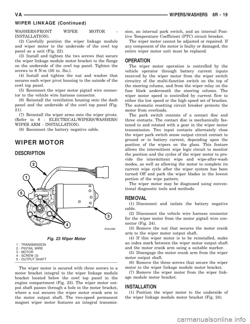
DESCRIPTION
The wiper motor is secured with three screws to a
motor bracket integral to the wiper linkage module
bracket located below the cowl top panel in the
engine compartment (Fig. 23). The wiper motor out-
put shaft passes through a hole in the motor bracket,
where a nut secures the wiper motor crank arm to
the motor output shaft. The two-speed permanent
magnet wiper motor features an integral transmis-sion, an internal park switch, and an internal Posi-
tive Temperature Coefficient (PTC) circuit breaker.
The wiper motor cannot be adjusted or repaired. If
any component of the motor is faulty or damaged, the
entire wiper motor unit must be replaced.
OPERATION
The wiper motor operation is controlled by the
vehicle operator through battery current inputs
received by the wiper motor from the wiper switch
circuitry of the multi-function switch on the top of
the steering column, and from the wiper relay on the
fuse block underneath the steering column. The
wiper motor speed is controlled by current flow to
either the low speed or the high speed set of brushes.
The automatic resetting circuit breaker protects the
motor from overloads.
The park switch consists of a contact disc and
three contacts. The contact disc is mechanically fas-
tened to and rotated with a gear in the wiper motor
transmission. Two input contacts alternately close
the wiper park switch sense output circuit contact to
ground or to battery current, depending upon the
position of the wipers on the glass. This feature
allows the intermittent wipe logic circuit to monitor
the position and the cycles of the wiper motor to pro-
vide the intermittent wipe and wipe-after-wash
modes, as well as allowing the motor to complete its
current wipe cycle after the wiper system has been
turned Off and park the wiper blades in the lowest
portion of the wipe pattern.
The wiper motor may be diagnosed using conven-
tional diagnostic tools and methods.
REMOVAL
(1) Disconnect and isolate the battery negative
cable.
(2) Disconnect the vehicle wire harness connector
for the wiper motor from the motor pigtail wire con-
nector (Fig. 24).
(3) Remove the nut that secures the motor crank
arm to the wiper motor output shaft.
(4) If this wiper motor is to be reinstalled, make
an index mark between the wiper motor output shaft
and the motor crank arm using a suitable marker.
(5) Disengage the motor crank arm from the wiper
motor output shaft.
(6) Remove the three screws that secure the wiper
motor to the wiper linkage module motor bracket.
(7) Remove the wiper motor from the wiper link-
age module motor bracket.
INSTALLATION
(1) Position the wiper motor to the underside of
the wiper linkage module motor bracket (Fig. 24).
Fig. 23 Wiper Motor
1 - TRANSMISSION
2 - PIGTAIL WIRE
3 - MOTOR
4 - SCREW (3)
5 - OUTPUT SHAFT
VAWIPERS/WASHERS 8R - 19
WIPER LINKAGE (Continued)
Page 733 of 1232
8W-97 POWER DISTRIBUTION
TABLE OF CONTENTS
page page
POWER DISTRIBUTION
DESCRIPTION..........................1
OPERATION............................1
CIGAR LIGHTER OUTLET
DESCRIPTION..........................1
OPERATION............................2
DIAGNOSIS AND TESTING - CIGAR LIGHTER
OUTLET.............................2
REMOVAL.............................2
CIRCUIT BREAKER
DESCRIPTION..........................2
OPERATION............................2
DIAGNOSIS AND TESTING - CIRCUIT
BREAKER............................2
FUSE BLOCK #1
DESCRIPTION..........................2
OPERATION............................2
REMOVAL.............................3
INSTALLATION..........................3FUSE BLOCK #2
DESCRIPTION..........................3
OPERATION............................3
POWER DISTRIBUTION CENTER
DESCRIPTION..........................3
OPERATION............................3
POWER OUTLET
DESCRIPTION..........................3
OPERATION............................4
DIAGNOSIS AND TESTING - POWER OUTLET . 4
REMOVAL.............................4
INSTALLATION..........................4
RELAY
DESCRIPTION..........................4
OPERATION............................5
DIAGNOSIS AND TESTING - RELAY.........5
REMOVAL.............................5
INSTALLATION..........................5
POWER DISTRIBUTION
DESCRIPTION
This section describes the power distribution com-
ponents used on this model as well as the methods in
which battery voltage and charging system voltage is
distributed throughout the vehicle. The power distri-
bution system for this vehicle consists of the follow-
ing major components which are covered in further
detail later in this section:
²Fuseblock #1
²Fuseblock #2
²Power Distribution Center (PDC)
The power distribution system also incorporates
various types of circuit control and protection fea-
tures, including:
²Automatic resetting circuit breakers
²Blade-type fuses
²Cartridge fuses
²Relays
Following are general descriptions and theory of
operation for the major components in the power dis-
tribution system. Refer to Wiring for the location of
complete circuit diagrams for the various power dis-
tribution system components.
OPERATION
The power distribution system for this vehicle is
designed to provide safe, reliable, and centralized dis-
tribution points for the electrical current required to
operate all of the standard and optional factory-in-
stalled electrical and powertrain, chassis, safety,
security and convenience systems. At the same time,
the power distribution system was designed to pro-
vide easy access to these electrical distribution points
for the vehicle technician to use when conducting
diagnosis and repair of faulty circuits. The power dis-
tribution system can also prove useful for the addi-
tion of electrical circuits that may be required to
operate accessories that the vehicle owner may
choose to have installed in the aftermarket.
CIGAR LIGHTER OUTLET
DESCRIPTION
The cigar lighter outlet is installed in the instru-
ment panel, near the center of the instrument panel.
The cigar lighter outlet is secured by a snap fit
within the instrument panel.
The cigar lighter knob/heating element, and the
cigar lighter outlet are available for service. These
components cannot be repaired and, if faulty or dam-
aged, they must be replaced.
VA8W-97 POWER DISTRIBUTION 8W - 97 - 1