2005 MERCEDES-BENZ SPRINTER wheel bolt torque
[x] Cancel search: wheel bolt torquePage 22 of 1232
FRONT
SPECIFICATIONS - TORQUE CHART
TORQUE SPECIFICATIONS
DESCRIPTION N´m Ft. Lbs. In. Lbs.
Lower Ball Joint To
Steering Knuckle280 206 Ð
Strut To Steering Knuckle 185 136 Ð
Strut To Body 100 74 Ð
Bottom Spring Clamp
Plate To Front Axle
M12 X 1.5 Bolt130 96 Ð
Bottom Spring Clamp
Plate To Front Axle
M10 Bolt65 48 Ð
Sway Bar Clamp To The
Front Axle30 22 Ð
Hexagon Socket Bolt For
Clamping Nut To Adjust
Wheel Bearing Play12 9 106
Lower Control Arm To
Front Axle Beam150 110 Ð
Stop Plate For Lower
Control Arm60 44 Ð
Outer Tie Rod End Nut 130 96 Ð
Outer Tie Rod End Nut
Jam Nut50 37 Ð
SPECIAL TOOLS
FRONT SUSPENSION
SPECIAL TOOL CROSS REFERENCE CHART
MB
TOOL #MILLER
TOOL #DESCRIPTION
N/A 9288 LEAF SPRING WEDGE
BLOCK
N/A 9294 LOWER BALL JOINT
REMOVE/INSTALLER
N/A 9302 BUSHING REMOVER
/INSTALLER
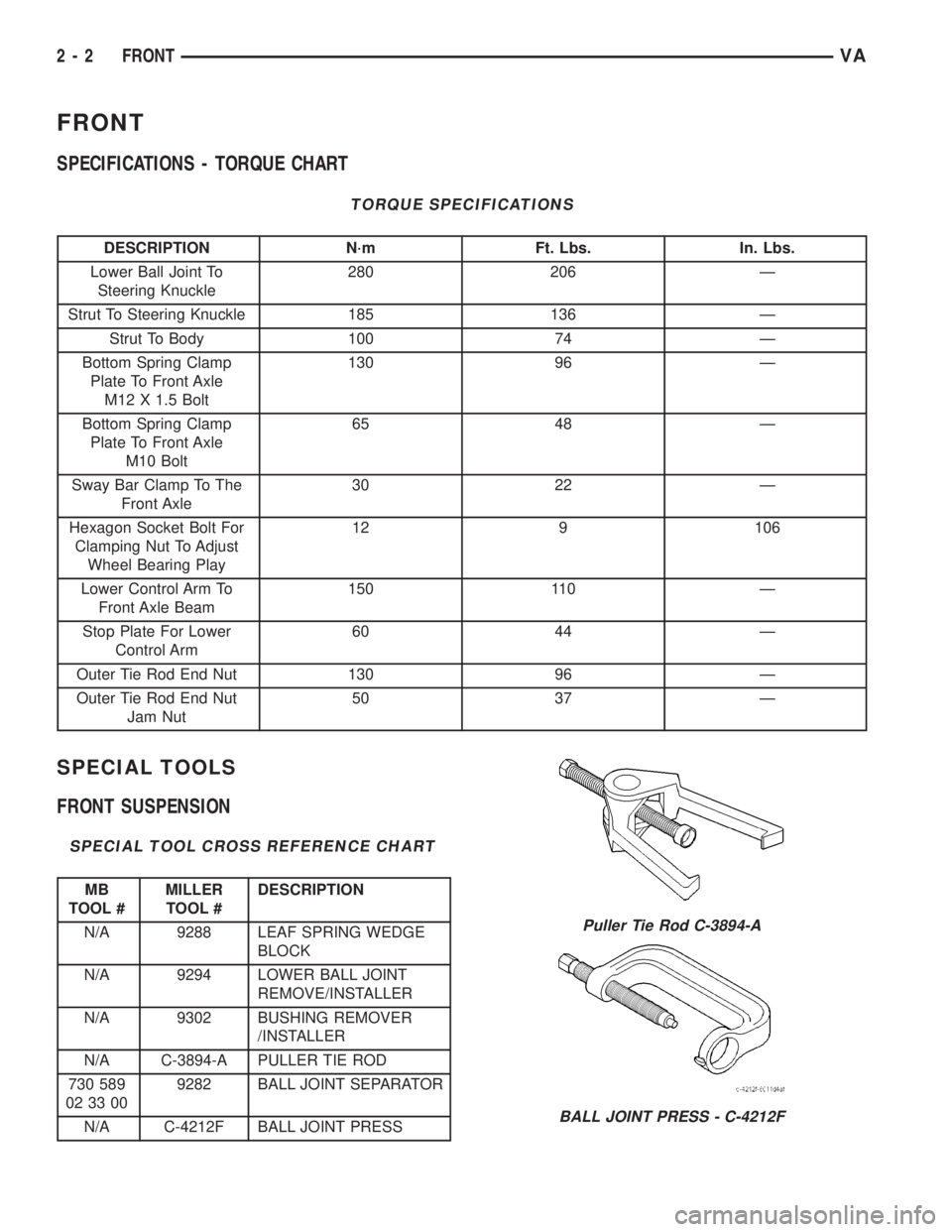
N/A C-3894-A PULLER TIE ROD
730 589
02 33 009282 BALL JOINT SEPARATOR
N/A C-4212F BALL JOINT PRESS
Puller Tie Rod C-3894-A
BALL JOINT PRESS - C-4212F
2 - 2 FRONTVA
Page 42 of 1232
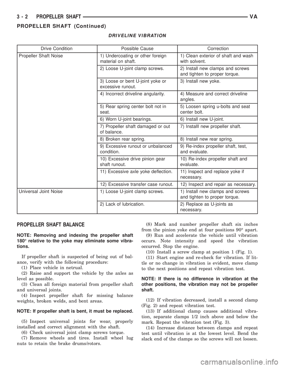
DRIVELINE VIBRATION
Drive Condition Possible Cause Correction
Propeller Shaft Noise 1) Undercoating or other foreign
material on shaft.1) Clean exterior of shaft and wash
with solvent.
2) Loose U-joint clamp screws. 2) Install new clamps and screws
and tighten to proper torque.
3) Loose or bent U-joint yoke or
excessive runout.3) Install new yoke.
4) Incorrect driveline angularity. 4) Measure and correct driveline
angles.
5) Rear spring center bolt not in
seat.5) Loosen spring u-bolts and seat
center bolt.
6) Worn U-joint bearings. 6) Install new U-joint.
7) Propeller shaft damaged or out
of balance.7) Installl new propeller shaft.
8) Broken rear spring. 8) Install new rear spring.
9) Excessive runout or unbalanced
condition.9) Re-index propeller shaft, test,
and evaluate.
10) Excessive drive pinion gear
shaft runout.10) Re-index propeller shaft and
evaluate.
11) Excessive axle yoke deflection. 11) Inspect and replace yoke if
necessary.
12) Excessive transfer case runout. 12) Inspect and repair as necessary.
Universal Joint Noise 1) Loose U-joint clamp screws. 1) Install new clamps and screws
and tighten to proper torque.
2) Lack of lubrication. 2) Replace as U-joints as
necessary.
PROPELLER SHAFT BALANCE
NOTE: Removing and indexing the propeller shaft
180É relative to the yoke may eliminate some vibra-
tions.
If propeller shaft is suspected of being out of bal-
ance, verify with the following procedure:
(1) Place vehicle in netrual.
(2) Raise and support the vehicle by the axles as
level as possible.
(3) Clean all foreign material from propeller shaft
and universal joints.
(4) Inspect propeller shaft for missing balance
weights, broken welds, and bent areas.
NOTE: If propeller shaft is bent, it must be replaced.
(5) Inspect universal joints for wear, properly
installed and correct alignment with the shaft.
(6) Check universal joint clamp screws torque.
(7) Remove wheels and tires. Install wheel lug
nuts to retain the brake drums/rotors.(8) Mark and number propeller shaft six inches
from the pinion yoke end at four positions 90É apart.
(9) Run and accelerate the vehicle until vibration
occurs. Note intensity and speed the vibration
occurred. Stop the engine.
(10) Install a screw clamp at position 1 (Fig. 1).
(11) Start engine and re-check for vibration. If lit-
tle or no change in vibration is evident, move clamp
to the next positions and repeat vibration test.
NOTE: If there is no difference in vibration at the
other positions, the vibration may not be propeller
shaft.
(12) If vibration decreased, install a second clamp
(Fig. 2) and repeat vibration test.
(13) If additional clamp causes additional vibra-
tion, separate clamps 1/2 inch above and below the
mark. Repeat the vibration test (Fig. 3).
(14) Increase distance between clamps and repeat
test until vibration is at the lowest level. Bend the
slack end of the clamps so the screws will not loosen.
3 - 2 PROPELLER SHAFTVA
PROPELLER SHAFT (Continued)
Page 69 of 1232
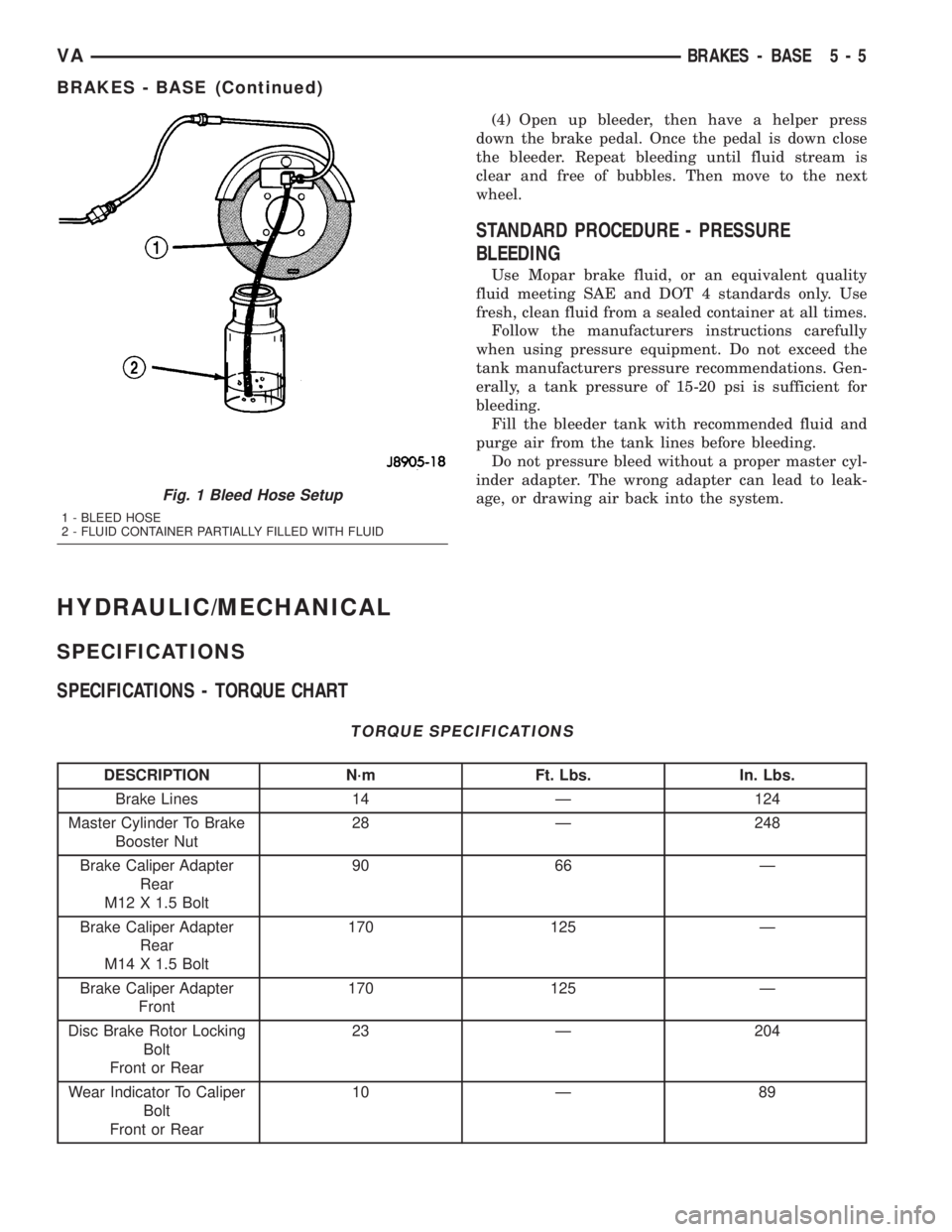
(4) Open up bleeder, then have a helper press
down the brake pedal. Once the pedal is down close
the bleeder. Repeat bleeding until fluid stream is
clear and free of bubbles. Then move to the next
wheel.
STANDARD PROCEDURE - PRESSURE
BLEEDING
Use Mopar brake fluid, or an equivalent quality
fluid meeting SAE and DOT 4 standards only. Use
fresh, clean fluid from a sealed container at all times.
Follow the manufacturers instructions carefully
when using pressure equipment. Do not exceed the
tank manufacturers pressure recommendations. Gen-
erally, a tank pressure of 15-20 psi is sufficient for
bleeding.
Fill the bleeder tank with recommended fluid and
purge air from the tank lines before bleeding.
Do not pressure bleed without a proper master cyl-
inder adapter. The wrong adapter can lead to leak-
age, or drawing air back into the system.
HYDRAULIC/MECHANICAL
SPECIFICATIONS
SPECIFICATIONS - TORQUE CHART
TORQUE SPECIFICATIONS
DESCRIPTION N´m Ft. Lbs. In. Lbs.
Brake Lines 14 Ð 124
Master Cylinder To Brake
Booster Nut28 Ð 248
Brake Caliper Adapter
Rear
M12 X 1.5 Bolt90 66 Ð
Brake Caliper Adapter
Rear
M14 X 1.5 Bolt170 125 Ð
Brake Caliper Adapter
Front170 125 Ð
Disc Brake Rotor Locking
Bolt
Front or Rear23 Ð 204
Wear Indicator To Caliper
Bolt
Front or Rear10 Ð 89
Fig. 1 Bleed Hose Setup
1 - BLEED HOSE
2 - FLUID CONTAINER PARTIALLY FILLED WITH FLUID
VABRAKES - BASE 5 - 5
BRAKES - BASE (Continued)
Page 86 of 1232
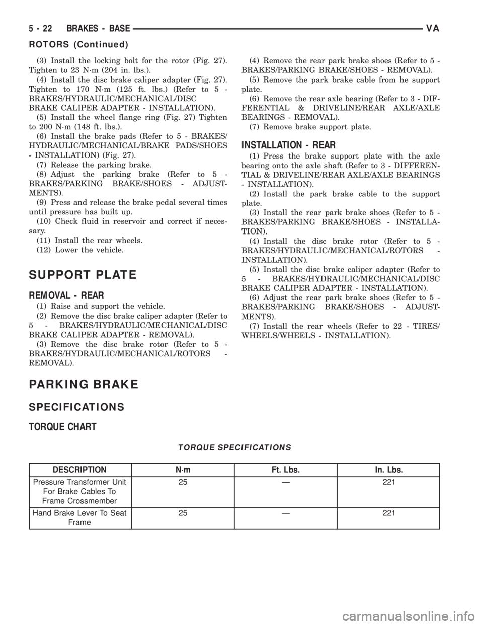
(3) Install the locking bolt for the rotor (Fig. 27).
Tighten to 23 N´m (204 in. lbs.).
(4) Install the disc brake caliper adapter (Fig. 27).
Tighten to 170 N´m (125 ft. lbs.) (Refer to 5 -
BRAKES/HYDRAULIC/MECHANICAL/DISC
BRAKE CALIPER ADAPTER - INSTALLATION).
(5) Install the wheel flange ring (Fig. 27) Tighten
to 200 N´m (148 ft. lbs.).
(6) Install the brake pads (Refer to 5 - BRAKES/
HYDRAULIC/MECHANICAL/BRAKE PADS/SHOES
- INSTALLATION) (Fig. 27).
(7) Release the parking brake.
(8) Adjust the parking brake (Refer to 5 -
BRAKES/PARKING BRAKE/SHOES - ADJUST-
MENTS).
(9) Press and release the brake pedal several times
until pressure has built up.
(10) Check fluid in reservoir and correct if neces-
sary.
(11) Install the rear wheels.
(12) Lower the vehicle.
SUPPORT PLATE
REMOVAL - REAR
(1) Raise and support the vehicle.
(2) Remove the disc brake caliper adapter (Refer to
5 - BRAKES/HYDRAULIC/MECHANICAL/DISC
BRAKE CALIPER ADAPTER - REMOVAL).
(3) Remove the disc brake rotor (Refer to 5 -
BRAKES/HYDRAULIC/MECHANICAL/ROTORS -
REMOVAL).(4) Remove the rear park brake shoes (Refer to 5 -
BRAKES/PARKING BRAKE/SHOES - REMOVAL).
(5) Remove the park brake cable from he support
plate.
(6) Remove the rear axle bearing (Refer to 3 - DIF-
FERENTIAL & DRIVELINE/REAR AXLE/AXLE
BEARINGS - REMOVAL).
(7) Remove brake support plate.
INSTALLATION - REAR
(1) Press the brake support plate with the axle
bearing onto the axle shaft (Refer to 3 - DIFFEREN-
TIAL & DRIVELINE/REAR AXLE/AXLE BEARINGS
- INSTALLATION).
(2) Install the park brake cable to the support
plate.
(3) Install the rear park brake shoes (Refer to 5 -
BRAKES/PARKING BRAKE/SHOES - INSTALLA-
TION).
(4) Install the disc brake rotor (Refer to 5 -
BRAKES/HYDRAULIC/MECHANICAL/ROTORS -
INSTALLATION).
(5) Install the disc brake caliper adapter (Refer to
5 - BRAKES/HYDRAULIC/MECHANICAL/DISC
BRAKE CALIPER ADAPTER - INSTALLATION).
(6) Adjust the rear park brake shoes (Refer to 5 -
BRAKES/PARKING BRAKE/SHOES - ADJUST-
MENTS).
(7) Install the rear wheels (Refer to 22 - TIRES/
WHEELS/WHEELS - INSTALLATION).
PARKING BRAKE
SPECIFICATIONS
TORQUE CHART
TORQUE SPECIFICATIONS
DESCRIPTION N´m Ft. Lbs. In. Lbs.
Pressure Transformer Unit
For Brake Cables To
Frame Crossmember25 Ð 221
Hand Brake Lever To Seat
Frame25 Ð 221
5 - 22 BRAKES - BASEVA
ROTORS (Continued)
Page 739 of 1232
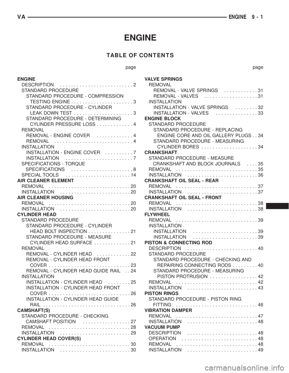
ENGINE
TABLE OF CONTENTS
page page
ENGINE
DESCRIPTION..........................2
STANDARD PROCEDURE
STANDARD PROCEDURE - COMPRESSION
TESTING ENGINE......................3
STANDARD PROCEDURE - CYLINDER
LEAK DOWN TEST.....................3
STANDARD PROCEDURE - DETERMINING
CYLINDER PRESSURE LOSS.............4
REMOVAL
REMOVAL - ENGINE COVER.............4
REMOVAL............................4
INSTALLATION
INSTALLATION - ENGINE COVER..........7
INSTALLATION........................7
SPECIFICATIONS - TORQUE
SPECIFICATIONS......................8
SPECIAL TOOLS.......................14
AIR CLEANER ELEMENT
REMOVAL.............................20
INSTALLATION.........................20
AIR CLEANER HOUSING
REMOVAL.............................20
INSTALLATION.........................20
CYLINDER HEAD
STANDARD PROCEDURE
STANDARD PROCEDURE - CYLINDER
HEAD BOLT INSPECTION...............21
STANDARD PROCEDURE - MEASURE
CYLINDER HEAD SURFACE.............21
REMOVAL
REMOVAL - CYLINDER HEAD............22
REMOVAL - CYLINDER HEAD FRONT
COVER.............................23
REMOVAL - CYLINDER HEAD GUIDE RAIL . . 24
INSTALLATION
INSTALLATION - CYLINDER HEAD........25
INSTALLATION - CYLINDER HEAD FRONT
COVER.............................26
INSTALLATION - CYLINDER HEAD GUIDE
RAIL...............................26
CAMSHAFT(S)
STANDARD PROCEDURE - CHECKING
CAMSHAFT POSITION.................27
REMOVAL.............................28
INSTALLATION.........................29
CYLINDER HEAD COVER(S)
REMOVAL.............................30
INSTALLATION.........................30VALVE SPRINGS
REMOVAL
REMOVAL - VALVE SPRINGS............31
REMOVAL - VALVES...................31
INSTALLATION
INSTALLATION - VALVE SPRINGS........32
INSTALLATION - VALVES...............33
ENGINE BLOCK
STANDARD PROCEDURE
STANDARD PROCEDURE - REPLACING
ENGINE CORE AND OIL GALLERY PLUGS . . 34
STANDARD PROCEDURE - MEASURING
CYLINDER BORES....................34
CRANKSHAFT
STANDARD PROCEDURE - MEASURE
CRANKSHAFT AND BLOCK JOURNALS....35
REMOVAL.............................35
INSTALLATION.........................36
CRANKSHAFT OIL SEAL - REAR
REMOVAL.............................37
INSTALLATION.........................37
CRANKSHAFT OIL SEAL - FRONT
REMOVAL.............................38
INSTALLATION.........................38
FLYWHEEL
REMOVAL.............................39
INSTALLATION
INSTALLATION.......................39
INSTALLATION.......................39
PISTON & CONNECTING ROD
DESCRIPTION.........................40
STANDARD PROCEDURE
STANDARD PROCEDURE - CHECKING AND
REPAIRING CONNECTING RODS.........40
STANDARD PROCEDURE - MEASURING
PISTON PROTRUSION.................42
REMOVAL.............................42
INSTALLATION.........................43
PISTON RINGS
STANDARD PROCEDURE - PISTON RING
FITTING.............................46
VIBRATION DAMPER
REMOVAL.............................47
INSTALLATION.........................48
VACUUM PUMP
DESCRIPTION.........................48
OPERATION...........................48
REMOVAL.............................48
INSTALLATION.........................49
VAENGINE 9 - 1
Page 747 of 1232
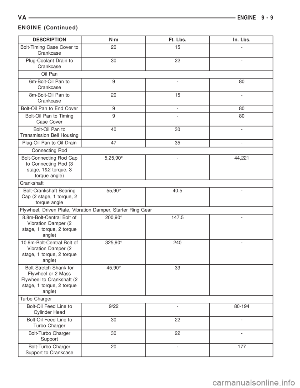
DESCRIPTION N´m Ft. Lbs. In. Lbs.
Bolt-Timing Case Cover to
Crankcase20 15 -
Plug-Coolant Drain to
Crankcase30 22 -
Oil Pan
6m-Bolt-Oil Pan to
Crankcase9-80
8m-Bolt-Oil Pan to
Crankcase20 15 -
Bolt-Oil Pan to End Cover 9 - 80
Bolt-Oil Pan to Timing
Case Cover9-80
Bolt-Oil Pan to
Transmission Bell Housing40 30 -
Plug-Oil Pan to Oil Drain 47 35 -
Connecting Rod
Bolt-Connecting Rod Cap
to Connecting Rod (3
stage, 1&2 torque, 3
torque angle)5,25,90É - 44,221
Crankshaft
Bolt-Crankshaft Bearing
Cap (2 stage, 1 torque, 2
torque angle55,90É 40.5 -
Flywheel, Driven Plate, Vibration Damper, Starter Ring Gear
8.8m-Bolt-Central Bolt of
Vibration Damper (2
stage, 1 torque, 2 torque
angle)200,90É 147.5 -
10.9m-Bolt-Central Bolt of
Vibration Damper (2
stage, 1 torque, 2 torque
angle)325,90É 240 -
Bolt-Stretch Shank for
Flywheel or 2 Mass
Flywheel to Crankshaft (2
stage, 1 torque, 2 torque
angle)45,90É 33
Turbo Charger
Bolt-Oil Feed Line to
Cylinder Head9/22 - 80-194
Bolt-Oil Feed Line to
Turbo Charger30 22 -
Bolt-Turbo Charger
Support30 22 -
Bolt-Turbo Charger
Support to Crankcase20 - 177
VAENGINE 9 - 9
ENGINE (Continued)
Page 777 of 1232
FLYWHEEL
REMOVAL
(1) Remove transmission (Refer to 21 - TRANS-
MISSION/TRANSAXLE/AUTOMATIC - W5J400 -
REMOVAL).
NOTE: M6x90 bolts must be used with retaining
lock to prevent damage to rear end cover.
(2) Install retaining lock for crankshaft/starter
ring gear.
NOTE: Flywheel does not need balancing or should
it be interchanged.
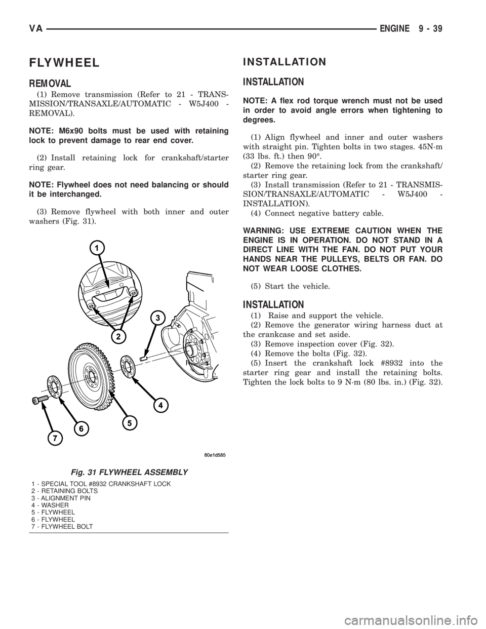
(3) Remove flywheel with both inner and outer
washers (Fig. 31).
INSTALLATION
INSTALLATION
NOTE: A flex rod torque wrench must not be used
in order to avoid angle errors when tightening to
degrees.
(1) Align flywheel and inner and outer washers
with straight pin. Tighten bolts in two stages. 45N´m
(33 lbs. ft.) then 90É.
(2) Remove the retaining lock from the crankshaft/
starter ring gear.
(3) Install transmission (Refer to 21 - TRANSMIS-
SION/TRANSAXLE/AUTOMATIC - W5J400 -
INSTALLATION).
(4) Connect negative battery cable.
WARNING: USE EXTREME CAUTION WHEN THE
ENGINE IS IN OPERATION. DO NOT STAND IN A
DIRECT LINE WITH THE FAN. DO NOT PUT YOUR
HANDS NEAR THE PULLEYS, BELTS OR FAN. DO
NOT WEAR LOOSE CLOTHES.
(5) Start the vehicle.
INSTALLATION
(1) Raise and support the vehicle.
(2) Remove the generator wiring harness duct at
the crankcase and set aside.
(3) Remove inspection cover (Fig. 32).
(4) Remove the bolts (Fig. 32).
(5) Insert the crankshaft lock #8932 into the
starter ring gear and install the retaining bolts.
Tighten the lock bolts to 9 N´m (80 lbs. in.) (Fig. 32).
Fig. 31 FLYWHEEL ASSEMBLY
1 - SPECIAL TOOL #8932 CRANKSHAFT LOCK
2 - RETAINING BOLTS
3 - ALIGNMENT PIN
4 - WASHER
5 - FLYWHEEL
6 - FLYWHEEL
7 - FLYWHEEL BOLT
VAENGINE 9 - 39
Page 865 of 1232
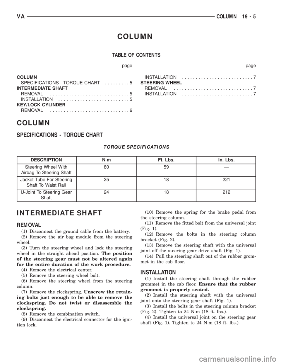
COLUMN
TABLE OF CONTENTS
page page
COLUMN
SPECIFICATIONS - TORQUE CHART.........5
INTERMEDIATE SHAFT
REMOVAL.............................5
INSTALLATION..........................5
KEY/LOCK CYLINDER
REMOVAL.............................6INSTALLATION..........................7
STEERING WHEEL
REMOVAL.............................7
INSTALLATION..........................7
COLUMN
SPECIFICATIONS - TORQUE CHART
TORQUE SPECIFICATIONS
DESCRIPTION N´m Ft. Lbs. In. Lbs.
Steering Wheel With
Airbag To Steering Shaft80 59 Ð
Jacket Tube For Steering
Shaft To Waist Rail25 18 221
U-Joint To Steering Gear
Shaft24 18 212
INTERMEDIATE SHAFT
REMOVAL
(1) Disconnect the ground cable from the battery.
(2) Remove the air bag module from the steering
wheel.
(3) Turn the steering wheel and lock the steering
wheel in the straight ahead position.The position
of the steering gear must not be altered again
for the entire duration of the work procedure.
(4) Remove the electrical center.
(5) Remove the steering wheel bolt.
(6) Remove the steering wheel from the steering
column.
(7) Remove the clockspring.Unscrew the retain-
ing bolts just enough to be able to remove the
clockspring. Do not twist or disassemble the
clockspring.
(8) Remove the combination switch.
(9) Disconnect the electrical connector for the igni-
tion lock.(10) Remove the spring for the brake pedal from
the steering column.
(11) Remove the fitted bolt from the universal joint
(Fig. 1).
(12) Remove the bolts in the steering column
bracket (Fig. 2).
(13) Remove the steering shaft with the universal
joint off the steering gear drive shaft (Fig. 1).
(14) Pull the steering shaft out of the rubber grom-
met in the cab floor.
INSTALLATION
(1) Install the steering shaft through the rubber
grommet in the cab floor.Ensure that the rubber
grommet is properly seated.
(2) Install the steering shaft with the universal
joint onto the steering gear shaft (Fig. 1).
(3) Install the bolts in the steering column bracket
(Fig. 2). Tighten to 24 N´m (18 ft. lbs.).
(4) Install the universal joint on the steering gear
shaft (Fig. 1). Tighten to 24 N´m (18 ft. lbs.).
VACOLUMN 19 - 5