2005 MERCEDES-BENZ SPRINTER change time
[x] Cancel search: change timePage 68 of 1232
A worn, damaged wheel bearing or suspension
component are further causes of pull. A damaged
front tire (bruised, ply separation) can also cause
pull.
A common and frequently misdiagnosed pull condi-
tion is where direction of pull changes after a few
stops. The cause is a combination of brake drag fol-
lowed by fade at one of the brake units.
As the dragging brake overheats, efficiency is so
reduced that fade occurs. Since the opposite brake
unit is still functioning normally, its braking effect is
magnified. This causes pull to switch direction in
favor of the normally functioning brake unit.
An additional point when diagnosing a change in
pull condition concerns brake cool down. Remember
that pull will return to the original direction, if the
dragging brake unit is allowed to cool down (and is
not seriously damaged).
REAR BRAKE GRAB OR PULL
Rear grab or pull is usually caused by improperly
adjusted or seized parking brake cables, contami-
nated lining, bent or binding shoes and support
plates, or improperly assembled components. This is
particularly true when only one rear wheel is
involved. However, when both rear wheels are
affected, the master cylinder or proportioning valve
could be at fault.
BRAKES DO NOT HOLD AFTER DRIVING THROUGH DEEP
WATER PUDDLES
This condition is generally caused by water soaked
lining. If the lining is only wet, it can be dried by
driving with the brakes very lightly applied for a
mile or two. However, if the lining is both soaked and
dirt contaminated, cleaning and/or replacement will
be necessary.
BRAKE LINING CONTAMINATION
Brake lining contamination is mostly a product of
leaking calipers or worn seals, driving through deep
water puddles, or lining that has become covered
with grease and grit during repair. Contaminated lin-
ing should be replaced to avoid further brake prob-
lems.
WHEEL AND TIRE PROBLEMS
Some conditions attributed to brake components
may actually be caused by a wheel or tire problem.
A damaged wheel can cause shudder, vibration and
pull. A worn or damaged tire can also cause pull.
Severely worn tires with very little tread left can
produce a grab-like condition as the tire loses and
recovers traction. Flat-spotted tires can cause vibra-
tion and generate shudder during brake operation. A
tire with internal damage such as a severe bruise,
cut, or ply separation can cause pull and vibration.BRAKE NOISES
Some brake noise is common with rear drum
brakes and on some disc brakes during the first few
stops after a vehicle has been parked overnight or
stored. This is primarily due to the formation of trace
corrosion (light rust) on metal surfaces. This light
corrosion is typically cleared from the metal surfaces
after a few brake applications causing the noise to
subside.
BRAKE SQUEAK/SQUEAL
Brake squeak or squeal may be due to linings that
are wet or contaminated with brake fluid, grease, or
oil. Glazed linings and rotors with hard spots can
also contribute to squeak. Dirt and foreign material
embedded in the brake lining will also cause squeak/
squeal.
A very loud squeak or squeal is frequently a sign of
severely worn brake lining. If the lining has worn
through to the brake pads in spots, metal-to-metal
contact occurs. If the condition is allowed to continue,
rotors can become so scored that replacement is nec-
essary.
BRAKE CHATTER
Brake chatter is usually caused by loose or worn
components, or glazed/burnt lining. Rotors with hard
spots can also contribute to chatter. Additional causes
of chatter are out-of-tolerance rotors, brake lining not
securely attached to the shoes, loose wheel bearings
and contaminated brake lining.
THUMP/CLUNK NOISE
Thumping or clunk noises during braking are fre-
quentlynotcaused by brake components. In many
cases, such noises are caused by loose or damaged
steering, suspension, or engine components. However,
calipers that bind on the slide surfaces can generate
a thump or clunk noise.
STANDARD PROCEDURE
STANDARD PROCEDURE - MANUAL BLEEDING
Use Mopar brake fluid, or an equivalent quality
fluid meeting SAE and DOT 4 standards only. Use
fresh, clean fluid from a sealed container at all times.
(1) Remove reservoir filler caps and fill reservoir.
(2) If calipers, or wheel cylinders were overhauled,
open all caliper and wheel cylinder bleed screws.
Then close each bleed screw as fluid starts to drip
from it. Top off master cylinder reservoir once more
before proceeding.
(3) Attach one end of bleed hose to bleed screw
and insert opposite end in glass container partially
filled with brake fluid (Fig. 1). Be sure end of bleed
hose is immersed in fluid.
5 - 4 BRAKES - BASEVA
BRAKES - BASE (Continued)
Page 126 of 1232
The TCM continuously checks for electrical prob-
lems, mechanical problems, and some hydraulic prob-
lems. When a problem is sensed, the TCM stores a
diagnostic trouble code (DTC). Some of these codes
cause the transmission to go into9Limp-In9or
9default9mode. Some DTCs cause permanent
Limp-In and others cause temporary Limp-In. The
NAG1 defaults in the current gear position if a DTC
is detected, then after a key cycle the transmission
will go into Limp-in, which is mechanical 2nd gear.
Some DTCs may allow the transmission to resume
normal operation (recover) if the detected problem
goes away. A permanent Limp-In DTC will recover
when the key is cycled, but if the same DTC is
detected for three key cycles the system will not
recover and the DTC must be cleared from the TCM
with the DRBIIItscan tool.
TCM SIGNALS
The TCM registers one part of the input signals by
direct inputs, the other part by CAN C bus. In addi-
tion to the direct control of the actuators, the TCM
sends various output signals by CAN C bus to other
control modules.
Selector Lever Position
The TCM monitors the SLA for all shift lever posi-
tions via the CAN bus.
ATF Temperature Sensor
The ATF temperature sensor is a positive temper-
ature co-efficient (PTC) thermistor. It measures the
temperature of the transmission fluid and is a direct
input signal for the TCM. The temperature of the
ATF has an influence on the shifttime and resulting
shift quality. As the temperature rises, resistance
rises, and therefore, the probing voltage is decreas-
ing. Because of its registration, the shifting process
can be optimized in all temperature ranges.
The ATF temperature sensor is wired in series
with the park/neutral contact. The temperature sig-
nal is transmitted to the TCM only when the reed
contact of the park/neutral contact is closed because
the TCM only reads ATF temperature while in any
forward gear, or REVERSE. When the transmission
is in PARK or NEUTRAL, the TCM will substitute
the engine temperature for the ATF temperature.
Starter Interlock
The TCM monitors a contact switch wired in series
with the transmission temperature sensor to deter-
mine PARK and NEUTRAL positions. The contact
switch is open in PARK and NEUTRAL. The TCM
senses transmission temperature as high (switch
supply voltage), confirming switch status as open.
The TCM then broadcasts a message over CAN bus
to confirm switch status. The PCM receives thisinformation and allows operation of the starter cir-
cuit.
N2 and N3 Speed Sensors
The N2 and N3 Input Speed Sensors are two Hall-
effect speed sensors that are mounted internally in
the transmission and are used by the TCM to calcu-
late the transmission's input speed. Since the input
speed cannot be measured directly, two of the drive
elements are measured. Two input speed sensors
were required because both drive elements are not
active in all gears.
CAN C Bus Indirect Input Signals
A 2.5-volt bias (operating voltage) is present on the
CAN C bus any time the ignition switch is in the
RUN position. Both the TCM and the ABS apply this
bias. On this vehicle, the CAN C bus is used for mod-
ule data exchange only. The indirect inputs used on
the NAG1 electronic control system are:
²Wheel Speed Sensors.
²Brake Switch.
²Engine RPM.
²Engine Temperature.
²Cruise Control Status.
²Gear Limit Request.
²Throttle Position - 0% at idle, 100% at WOT. If
open, TCM assumes idle (0% throttle opening).
²Odometer Mileage
²Maximum Effective Torque.
²Engine in Limp-In Mode/Mileage Where DTC
Was Set.
BRAKE TRANSMISSION SHIFT INTERLOCK (BTSI)
The BTSI solenoid prevents shifting out of the
PARK position until the ignition key is in the RUN
position and the brake pedal is pressed. The TCM
controls the ground while the ignition switch supplies
power to the BTSI solenoid. The PCM monitors the
brake switch and broadcasts brake switch status
messages over the CAN C bus. If the park brake is
depressed and there is power (Run/Start) to SLA, the
BTSI solenoid deactivates.
SHIFT SCHEDULES
The basic shift schedule includes up and down-
shifts for all five gears. The TCM adapts the shift
program according to driving style, accelerator pedal
position and deviation of vehicle speed. Influencing
factors are:
²Road Conditions.
²Incline, Decline and Altitude.
²Trailer Operation, Loading.
²Engine Coolant Temperature.
²Cruise Control Operation.
²Sporty Driving Style.
8E - 6 ELECTRONIC CONTROL MODULESVA
TRANSMISSION CONTROL MODULE (Continued)
Page 127 of 1232
²Low and High ATF Temperature.
Upshift
To :1-2 2-3 3-4 4-5
Activated
By
Solenoid:1-2/4-5 2-3 3-4 1-2/4-5
Shift
Point (at
35.2% of
throttle)17.8
km/h
(11.6
mph)32.1
km/h
(19.95
mph)67.5
km/h
(41.94
mph)73.8
km/h
(45.86
mph)
Downshift
From:5-4 4-3 3-2 2-1
Activated
By
Solenoid:1-2/4-5 3-4 2-3 1-2/4-5
Shift
Point55.7
km/h
(34.61
mph)40.5
km/h
(25.17
mph)24.4
km/h
(15.16
mph)15.1
km/h
(9.38
mph)
DOWNSHIFT SAFETY
Selector lever downshifts are not performed if inad-
missible high engine rpm is sensed.
ADAPTATION
To equalize tolerances and wear, an automatic
adaptation takes place for:
²Shift Time.
²Clutch Filling Time.
²Clutch Filling Pressure.
²Torque Converter Lock-Up Control.
Adaptation data may be stored permanently and to
some extent, can be diagnosed.
Driving Style Adaptation
The shift point is modified in steps based on the
information from the inputs. The control module
looks at inputs such as:
²vehicle acceleration and deceleration (calculated
by the TCM).
²rate of change as well as the position of the
throttle pedal (fuel injection information from the
ECM).
²lateral acceleration (calculated by the TCM).
²gear change frequency (how often the shift
occurs).
Based on how aggressive the driver is, the TCM
moves up the shift so that the present gear is held a
little longer before the next upshift. If the driving
style is still aggressive, the shift point is modified up
to ten steps. If the driving returns to normal, thenthe shift point modification also returns to the base
position.
This adaptation has no memory. The adaptation to
driving style is nothing more than a shift point mod-
ification meant to assist an aggressive driver. The
shift points are adjusted for the moment and return
to base position as soon as the inputs are controlled
in a more rational manner.
Shift Time Adaptation (Shift Overlap Adaptation, Working
Pressure)
Shift time adaptation is the ability of the TCM to
electronically alter the time it takes to go from one
gear to another. Shift time is defined as the time it
takes to disengage one shift member while another is
being applied. Shift time adaptation is divided into
four categories:
33. Accelerating upshift, which is an upshift under
a load. For shift time adaptation for the 1-2 upshift
to take place, the transmission must shift from 1st to
2nd in six different engine load ranges vs. transmis-
sion output speed ranges.
34. Decelerating upshift, which is an upshift under
no load. This shift is a rolling upshift and is accom-
plished by letting the vehicle roll into the next gear.
35. Accelerating downshift, which is a downshift
under load. This shift can be initiated by the throttle,
with or without kickdown. The shift selector can also
be used.
36. Decelerating downshift, which is accomplished
by coasting down. As the speed of the vehicle
decreases, the transmission downshifts.
Fill Pressure Adaptation (Apply Pressure Adaptation,
Modulating Pressure)
Fill pressure adaptation is the ability of the TCM
to modify the pressure used to engage a shift mem-
ber. The value of this pressure determines how firm
the shift will be.
²If too much pressure is used, the shift will be
hard.
²If too little pressure is used, the transmission
may slip.
The pressure adjustment is needed to compensate
for the tolerances of the shift pressure solenoid valve.
The amount the solenoid valve opens as well as how
quickly the valve can move, has an effect on the pres-
sure. The return spring for the shift member pro-
vides a resistance that must be overcome by the
pressure in order for shift member to apply. These
return springs have slightly different values. This
also affects the application pressure and is compen-
sated for by fill pressure adaptation.
Fill Time Adaptation (Engagement Time Adaptation)
Fill time is the time it takes to fill the piston cav-
ity and take up any clearances for a friction element
VAELECTRONIC CONTROL MODULES 8E - 7
TRANSMISSION CONTROL MODULE (Continued)
Page 135 of 1232
lead dioxide (positive plate) or sponge lead (negative
plate). Insulators or plate separators made of a non-
conductive material are inserted between the positive
and negative plates to prevent them from contacting
or shorting against one another. These dissimilar
metal plates are submerged in a sulfuric acid and
water solution called an electrolyte.
The factory-installed low-maintenance bat-
tery has removable battery cell caps.Water can
be added to this battery. The chemical composition of
the metal coated plates within the low-maintenance
battery reduces battery gassing and water loss, at
normal charge and discharge rates. Therefore, the
battery should not require additional water in nor-
mal service. Rapid loss of electrolyte can be caused
by an overcharging condition. Be certain to diagnose
the charging system before returning the vehicle to
service.
OPERATION
The battery is designed to store electrical energy in
a chemical form. When an electrical load is applied to
the terminals of the battery, an electrochemical reac-
tion occurs. This reaction causes the battery to dis-
charge electrical current from its terminals. As the
battery discharges, a gradual chemical change takes
place within each cell. The sulfuric acid in the elec-
trolyte combines with the plate materials, causing
both plates to slowly change to lead sulfate. At the
same time, oxygen from the positive plate material
combines with hydrogen from the sulfuric acid, caus-
ing the electrolyte to become mainly water. The
chemical changes within the battery are caused by
the movement of excess or free electrons between the
positive and negative plate groups. This movement of
electrons produces a flow of electrical current
through the load device attached to the battery ter-
minals.
As the plate materials become more similar chem-
ically, and the electrolyte becomes less acid, the volt-
age potential of each cell is reduced. However, by
charging the battery with a voltage higher than that
of the battery itself, the battery discharging process
is reversed. Charging the battery gradually changes
the sulfated lead plates back into sponge lead and
lead dioxide, and the water back into sulfuric acid.
This action restores the difference in the electron
charges deposited on the plates, and the voltage
potential of the battery cells. For a battery to remain
useful, it must be able to produce high-amperage cur-
rent over an extended period. A battery must also be
able to accept a charge, so that its voltage potential
may be restored.
The battery is vented to release excess hydrogen
gas that is created when the battery is being charged
or discharged. However, even with these vents,hydrogen gas can collect in or around the battery. If
hydrogen gas is exposed to flame or sparks, it may
ignite. If the electrolyte level is low, the battery may
arc internally and explode. If the battery is equipped
with removable cell caps, add distilled water when-
ever the electrolyte level is below the top of the
plates. If the battery cell caps cannot be removed, the
battery must be replaced if the electrolyte level
becomes low.
DIAGNOSIS AND TESTING - BATTERY
The battery must be completely charged and the
terminals should be properly cleaned and inspected
before diagnostic procedures are performed. Refer to
Battery System Cleaning for the proper cleaning pro-
cedures, and Battery System Inspection for the
proper battery inspection procedures. Refer to Stan-
dard Procedures for the proper battery charging pro-
cedures.
MICRO 420 BATTERY TESTER
The Micro 420 automotive battery tester is
designed to help the dealership technicians diagnose
the cause of a defective battery. Follow the instruc-
tion manual supplied with the tester to properly
diagnose a vehicle. If the instruction manual is not
available refer to the standard procedure in this sec-
tion, which includes the directions for using the
Micro 420 battery tester.
WARNING: IF THE BATTERY SHOWS SIGNS OF
FREEZING, LEAKING OR LOOSE POSTS, DO NOT
TEST, ASSIST-BOOST, OR CHARGE. THE BATTERY
MAY ARC INTERNALLY AND EXPLODE. PERSONAL
INJURY AND/OR VEHICLE DAMAGE MAY RESULT.
WARNING: EXPLOSIVE HYDROGEN GAS FORMS IN
AND AROUND THE BATTERY. DO NOT SMOKE,
USE FLAME, OR CREATE SPARKS NEAR THE BAT-
TERY. PERSONAL INJURY AND/OR VEHICLE DAM-
AGE MAY RESULT.
WARNING: THE BATTERY CONTAINS SULFURIC
ACID, WHICH IS POISONOUS AND CAUSTIC. AVOID
CONTACT WITH THE SKIN, EYES, OR CLOTHING.
IN THE EVENT OF CONTACT, FLUSH WITH WATER
AND CALL A PHYSICIAN IMMEDIATELY. KEEP OUT
OF THE REACH OF CHILDREN.
A battery that will not accept a charge is faulty,
and must be replaced. Further testing is not
required. A fully-charged battery must be tested to
determine its cranking capacity. A battery that is ful-
ly-charged, but does not pass the Micro 420 or load
test, is faulty and must be replaced.
VABATTERY SYSTEM 8F - 7
BATTERY (Continued)
Page 170 of 1232
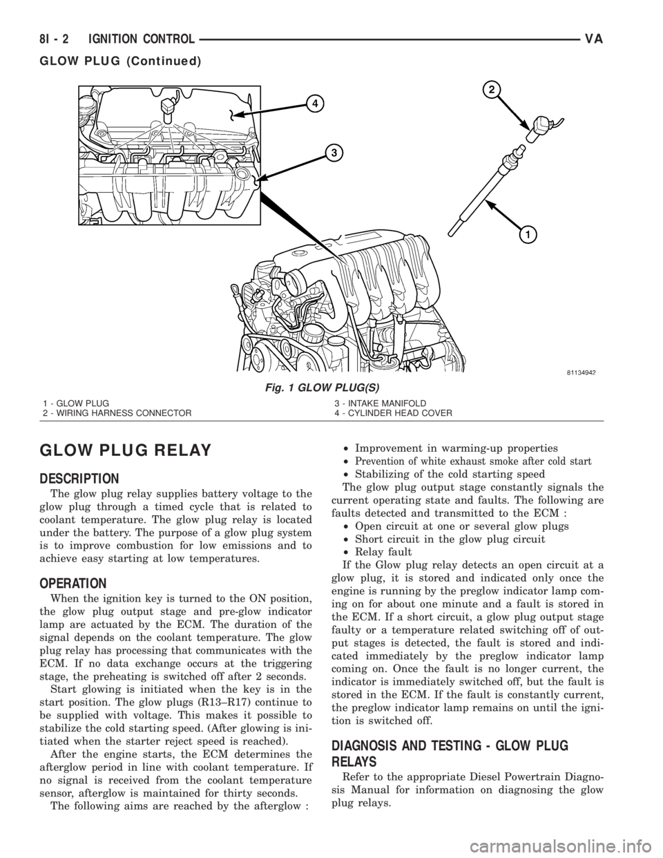
GLOW PLUG RELAY
DESCRIPTION
The glow plug relay supplies battery voltage to the
glow plug through a timed cycle that is related to
coolant temperature. The glow plug relay is located
under the battery. The purpose of a glow plug system
is to improve combustion for low emissions and to
achieve easy starting at low temperatures.
OPERATION
When the ignition key is turned to the ON position,
the glow plug output stage and pre-glow indicator
lamp are actuated by the ECM. The duration of the
signal depends on the coolant temperature. The glow
plug relay has processing that communicates with the
ECM. If no data exchange occurs at the triggering
stage, the preheating is switched off after 2 seconds.
Start glowing is initiated when the key is in the
start position. The glow plugs (R13±R17) continue to
be supplied with voltage. This makes it possible to
stabilize the cold starting speed. (After glowing is ini-
tiated when the starter reject speed is reached).
After the engine starts, the ECM determines the
afterglow period in line with coolant temperature. If
no signal is received from the coolant temperature
sensor, afterglow is maintained for thirty seconds.
The following aims are reached by the afterglow :²Improvement in warming-up properties
²
Prevention of white exhaust smoke after cold start
²Stabilizing of the cold starting speed
The glow plug output stage constantly signals the
current operating state and faults. The following are
faults detected and transmitted to the ECM :
²Open circuit at one or several glow plugs
²Short circuit in the glow plug circuit
²Relay fault
If the Glow plug relay detects an open circuit at a
glow plug, it is stored and indicated only once the
engine is running by the preglow indicator lamp com-
ing on for about one minute and a fault is stored in
the ECM. If a short circuit, a glow plug output stage
faulty or a temperature related switching off of out-
put stages is detected, the fault is stored and indi-
cated immediately by the preglow indicator lamp
coming on. Once the fault is no longer current, the
indicator is immediately switched off, but the fault is
stored in the ECM. If the fault is constantly current,
the preglow indicator lamp remains on until the igni-
tion is switched off.
DIAGNOSIS AND TESTING - GLOW PLUG
RELAYS
Refer to the appropriate Diesel Powertrain Diagno-
sis Manual for information on diagnosing the glow
plug relays.
Fig. 1 GLOW PLUG(S)
1 - GLOW PLUG
2 - WIRING HARNESS CONNECTOR3 - INTAKE MANIFOLD
4 - CYLINDER HEAD COVER
8I - 2 IGNITION CONTROLVA
GLOW PLUG (Continued)
Page 184 of 1232
using the ª+º (plus) and ª2º (minus) multi-function
indicator push buttons. The clock is serviced as a
unit with the instrument cluster.
OPERATION
The clock gives an indication to the vehicle opera-
tor of the current time. The electronic digital clock is
controlled by the instrument cluster microprocessor
based upon cluster programming. The clock display is
completely controlled by the instrument cluster logic
circuit, and that logic will only allow this indication
to be viewed when the multi-function indicator Liq-
uid Crystal Display (LCD) is activated. However, the
clock remains functional regardless of the ignition
switch position.
The vehicle operator can choose to have the
optional ambient temperature indicator displayed
instead of the clock information, but the clock and
ambient temperature indicator cannot be displayed
at the same time. The clock or ambient temperature
indicator display option is selected using the multi-
function indicator clock switch on the instrument
cluster circuit board. This switch is actuated manu-
ally by depressing the clock switch push button that
extends through the lower edge of the cluster lens
below the left end of the multi-function indicator.
Actuating this switch momentarily will toggle the
display between the clock and ambient temperature
indicator modes. Actuating this switch twice within
about one second will cause the display to toggle, but
then automatically revert to the originally selected
mode after about twenty seconds.
See the owner's manual in the vehicle glove box for
more information on the features, use, operation and
setting procedures for the clock. For proper testing of
the instrument cluster circuitry that controls the
clock functions, a DRBIIItscan tool is required.
Refer to the appropriate diagnostic information.
COOLANT LOW INDICATOR
DESCRIPTION
A coolant low indicator is standard equipment on
all instrument clusters. The coolant low indicator is
located near the lower edge of the instrument cluster,
to the left of the multi-function indicator display. The
coolant low indicator consists of the International
Control and Display Symbol icon for ªLow Engine
Coolantº imprinted within a rectangular cutout in
the opaque layer of the instrument cluster overlay.
The dark outer layer of the overlay prevents the indi-
cator from being clearly visible when it is not illumi-
nated. A red Light Emitting Diode (LED) behind the
cutout in the opaque layer of the overlay causes the
icon to appear silhouetted against a red field throughthe translucent outer layer of the overlay when the
indicator is illuminated from behind by the LED,
which is soldered onto the instrument cluster elec-
tronic circuit board. The coolant low indicator is ser-
viced as a unit with the instrument cluster.
OPERATION
The coolant low indicator gives an indication to the
vehicle operator when the engine coolant level is low.
This indicator is controlled by a transistor on the
instrument cluster circuit board based upon cluster
programming and a hard wired input received by the
cluster from the engine coolant level switch. The cool-
ant low indicator Light Emitting Diode (LED) is com-
pletely controlled by the instrument cluster logic
circuit, and that logic will only allow this indicator to
operate when the instrument cluster detects that the
ignition switch is in the On position. Therefore, the
LED will always be off when the ignition switch is in
any position except On. The LED only illuminates
when it is provided a path to ground by the instru-
ment cluster transistor. The instrument cluster will
turn on the coolant low indicator for the following
reasons:
²Bulb Test- Each time the ignition switch is
turned to the On position the coolant low indicator is
illuminated for about two seconds as a bulb test.
²Engine Coolant Level Switch Input- Each
time the cluster detects an appropriate input on the
low coolant fluid level sense circuit (engine coolant
level switch resistance low = engine coolant level low)
while the ignition switch is in the On position, the
coolant low indicator will be illuminated. The indica-
tor remains illuminated until the low coolant fluid
level sense input to the cluster changes (engine cool-
ant level switch resistance high = engine coolant
level full), or until the ignition switch is turned to
the Off position, whichever occurs first. The engine
coolant level switch also features a diagnostic resis-
tor connected in parallel between the switch input
and output to provide the cluster with verification
that the low coolant fluid level sense circuit is not
open or shorted.
The engine coolant level switch integral to the cool-
ant bottle provides a hard wired input to the instru-
ment cluster circuitry through the low coolant fluid
level sense circuit. The engine coolant level switch
and the low coolant fluid level sense circuit to the
instrument cluster can be diagnosed using conven-
tional diagnostic tools and methods. For proper diag-
nosis of the instrument cluster circuitry that controls
the coolant low indicator, a DRBIIItscan tool is
required. Refer to the appropriate diagnostic infor-
mation.
8J - 14 INSTRUMENT CLUSTERVA
CLOCK (Continued)
Page 186 of 1232
ule (ECM) over the Controller Area Network (CAN)
data bus. The fuel filter clogged indicator Light Emit-
ting Diode (LED) is completely controlled by the
instrument cluster logic circuit, and that logic will
only allow this indicator to operate when the instru-
ment cluster detects that the ignition switch is in the
On position. Therefore, the LED will always be off
when the ignition switch is in any position except
On. The LED only illuminates when it is provided a
path to ground by the instrument cluster transistor.
The instrument cluster will turn on the fuel filter
clogged indicator for the following reasons:
²Bulb Test- Each time the ignition switch is
turned to the On position the fuel filter clogged indi-
cator is illuminated by the cluster for about two sec-
onds as a bulb test.
²Fuel Filter Clogged Lamp-On Message-
Each time the cluster receives a lamp-on message
from the ECM, the fuel filter clogged indicator will
be illuminated. The indicator remains illuminated
until the cluster receives a lamp-off message from
the ECM, or until the ignition switch is turned to the
Off position, whichever occurs first.
The ECM continually monitors the low fuel pres-
sure sensor located at the inlet of the high pressure
fuel pump to decide whether the fuel system is in
good operating condition. The ECM then sends the
proper lamp-on or lamp-off messages to the instru-
ment cluster. If the ECM sends a lamp-on message
after the bulb test, it indicates that the ECM has
detected a low pressure condition in the fuel system,
which could result from a clogged fuel filter or from
any other restrictions in the fuel delivery system.
The ECM will store a Diagnostic Trouble Code (DTC)
for any malfunction it detects. For proper diagnosis
of the low fuel pressure sensor, the ECM, the CAN
data bus, the electronic message inputs to the instru-
ment cluster, or the instrument cluster circuitry that
controls the fuel filter clogged indicator, a DRBIIIt
scan tool is required. Refer to the appropriate diag-
nostic information.
FUEL GAUGE
DESCRIPTION
A fuel gauge is standard equipment on all instru-
ment clusters. The fuel gauge is located in the lower
right corner of the instrument cluster, to the right of
the speedometer. The fuel gauge consists of a mov-
able gauge needle or pointer controlled by the instru-
ment cluster circuitry and a fixed 45 degree scale on
the cluster overlay that reads left-to-right from ªFº
(or Full) to ªEº (or Empty). An International Control
and Display Symbol icon for ªFuelº is located on thecluster overlay, directly to the left of the low end of
the scale.
The fuel gauge graphics are white against a black
field, making them clearly visible within the instru-
ment cluster in daylight. When illuminated from
behind by the panel lamps dimmer controlled cluster
illumination lighting with the exterior lamps turned
On, the white graphics appear amber. The orange
gauge needle is internally illuminated. Gauge illumi-
nation is provided by Light Emitting Diode (LED)
units soldered onto the instrument cluster electronic
circuit board. The fuel gauge is serviced as a unit
with the instrument cluster.
OPERATION
The fuel gauge gives an indication to the vehicle
operator of the level of fuel in the fuel tank. This
gauge is controlled by the instrument cluster circuit
board based upon cluster programming and a hard
wired input received by the cluster from the fuel
level sensor in the fuel tank. The fuel gauge is an air
core magnetic unit that receives battery current on
the instrument cluster electronic circuit board when
the instrument cluster detects that the ignition
switch is in the On position. The cluster is pro-
grammed to move the gauge needle back to the low
end of the scale after the ignition switch is turned to
the Off position. The instrument cluster circuitry
controls the gauge needle position and provides the
following features:
²Fuel Level Sensor Input (At Ignition On)-
When the cluster detects the ignition switch has been
turned to the On position, the cluster moves the
gauge needle to the proper relative position on the
gauge scale as signaled by the fuel level sensor with-
out any electronic damping.
²Fuel Level Sensor Input (After Ignition On)
- After the ignition switch has been turned to the On
position, the cluster applies an algorithm to the input
from the fuel level sensor to electronically dampen
gauge needle movement against the negative effect
that fuel sloshing within the fuel tank can have on
accurate gauge readings.
²Fuel Level Sensor Input Open- If the fuel
level sensor input to the instrument cluster is an
open circuit, the cluster will move the fuel gauge nee-
dle to the ªEº (Empty) position on the gauge scale,
but the low fuel indicator will not be illuminated.
The fuel level sensor in the fuel tank provides a
hard wired input to the instrument cluster circuitry
through the fuel level sense circuit. The fuel level
sensor is a potentiometer that changes resistance
according to the fuel level. As the fuel level
decreases, the resistance through the fuel level sen-
sor increases. The fuel level sensor and the fuel level
sense circuit to the instrument cluster can be diag-
8J - 16 INSTRUMENT CLUSTERVA
FUEL FILTER CLOGGED INDICATOR (Continued)
Page 188 of 1232
²High Beams On Input- Each time the cluster
receives a high beam headlamps-on input from the
multi-function switch, the high beam indicator will
be illuminated. The indicator remains illuminated
until the cluster receives a high beam headlamps-off
input from the multi-function switch.
The instrument cluster continually monitors the
multi-function switch input to determine whether the
high beam indicator should be illuminated or extin-
guished. The multi-function switch and the multi-
function switch input circuit to the instrument
cluster can be diagnosed using conventional diagnos-
tic tools and methods. For proper diagnosis of the
instrument cluster circuitry that controls the high
beam indicator, a DRBIIItscan tool is required.
Refer to the appropriate diagnostic information.
LOW FUEL INDICATOR
DESCRIPTION
A low fuel indicator is standard equipment on all
instrument clusters. The low fuel indicator is located
directly below the low end of the fuel gauge scale.
The low fuel indicator consists of a small triangular
cutout in the opaque layer of the instrument cluster
overlay. The dark outer layer of the overlay prevents
the indicator from being clearly visible when it is not
illuminated. An amber Light Emitting Diode (LED)
behind the cutout in the opaque layer of the overlay
causes the triangle to appear in amber through the
translucent outer layer of the overlay when the indi-
cator is illuminated from behind by the LED, which
is soldered onto the instrument cluster electronic cir-
cuit board. The low fuel indicator is serviced as a
unit with the instrument cluster.
OPERATION
The low fuel indicator gives an indication to the
vehicle operator when the level of fuel in the fuel
tank becomes low. This indicator is controlled by a
transistor on the instrument cluster circuit board
based upon cluster programming and a hard wired
input received by the cluster from the fuel level sen-
sor in the fuel tank. The low fuel indicator Light
Emitting Diode (LED) is completely controlled by the
instrument cluster logic circuit, and that logic will
only allow this indicator to operate when the instru-
ment cluster detects that the ignition switch is in the
On position. Therefore, the LED will always be off
when the ignition switch is in any position except
On. The LED only illuminates when it is provided a
path to ground by the instrument cluster transistor.
The instrument cluster will turn on the low fuel indi-
cator for the following reasons:²Bulb Test- Each time the ignition switch is
turned to the On position the low fuel indicator is
illuminated for about two seconds as a bulb test.
²Fuel Level Sensor Input- Each time the clus-
ter receives an input from the fuel level sensor indi-
cating that the fuel level has reached about 12 liters
(3 gallons) or less, the low fuel indicator is illumi-
nated. The indicator remains illuminated until the
cluster receives an input from the fuel level sensor
indicating that the fuel level is above 12 liters (3 gal-
lons), or until the ignition switch is turned to the Off
position, whichever occurs first.
The fuel level sensor in the fuel tank provides a
hard wired input to the instrument cluster circuitry
through the fuel level sense circuit. The fuel level
sensor is a potentiometer that changes resistance
according to the fuel level. As the fuel level
decreases, the resistance through the fuel level sen-
sor increases. The fuel level sensor and the fuel level
sense circuit to the instrument cluster can be diag-
nosed using conventional diagnostic tools and meth-
ods. For proper diagnosis of the instrument cluster
circuitry that controls the fuel gauge, a DRBIIItscan
tool is required. Refer to the appropriate diagnostic
information.
LOW OIL LEVEL INDICATOR
DESCRIPTION
A low oil level indicator is standard equipment on
all instrument clusters. The low oil level indicator is
located near the lower edge of the instrument cluster,
to the left of the multi-function indicator display. The
low oil level indicator consists of the International
Control and Display Symbol icon for ªEngine Oilº
imprinted within a rectangular cutout in the opaque
layer of the instrument cluster overlay. The dark
outer layer of the overlay prevents the indicator from
being clearly visible when it is not illuminated. A red
Light Emitting Diode (LED) behind the cutout in the
opaque layer of the overlay causes the icon to appear
silhouetted against a red field through the translu-
cent outer layer of the overlay when the indicator is
illuminated from behind by the LED, which is sol-
dered onto the instrument cluster electronic circuit
board. The low oil level indicator is serviced as a unit
with the instrument cluster.
OPERATION
The low oil level indicator gives an indication to
the vehicle operator when the engine oil level is low.
This indicator is controlled by a transistor on the
instrument cluster electronic circuit board based
upon cluster programming and electronic messages
received by the cluster from the Engine Control Mod-
8J - 18 INSTRUMENT CLUSTERVA
HIGH BEAM INDICATOR (Continued)