2005 MERCEDES-BENZ SPRINTER oil change
[x] Cancel search: oil changePage 13 of 1232
down to -67.7ÉC (-90ÉF). A higher percentage will
freeze at a warmer temperature. Also, a higher per-
centage of antifreeze can cause the engine to over-
heat because specific heat of antifreeze is lower than
that of water.
CAUTION: Richer antifreeze mixtures cannot be
measured with normal field equipment and can
cause problems associated with 100 percent ethyl-
ene-glycol.
COOLANT SELECTION AND ADDITIVES
The use of aluminum cylinder blocks, cylinder
heads and water pumps requires special corrosion
protection. Only MopartAntifreeze/Coolant, 5
Year/100,000 Mile Formula (glycol base coolant with
corrosion inhibitors called HOAT, for Hybrid Organic
Additive Technology) is recommended. This coolant
offers the best engine cooling without corrosion when
mixed with 50% distilled water to obtain to obtain a
freeze point of -37ÉC (-34ÉF). If it loses color or
becomes contaminated, drain, flush, and replace with
fresh properly mixed coolant solution.
CAUTION: Do not use coolant additives that are
claimed to improve engine cooling.
DESCRIPTION - AXLE
NOTE: DaimlerChrysler recommends MoparTlubri-
cant or lubricant conforming to MS-8985.
REAR AXLE
²Synthetic Gear & Axle Lubricant SAE 75W-140
DESCRIPTION - BRAKE FLUID
NOTE: DaimlerChrysler recommends using DOT- 4
or equivalent brake fluid.
BRAKE FLUID
²DOT-4 or equivalent brake fluid.
DESCRIPTION - POWER STEERING FLUID
NOTE: DaimlerChrysler recommends using Mopar
ATF+4 Automatic Transmission fluid or equivalent.
POWER STEERING FLUID
²Mopar ATF+4 Automatic Transmission fluid or
equivalent.
DESCRIPTION - ENGINE OIL - DIESEL
ENGINES
SAE VISCOSITY GRADE
CAUTION: Low viscosity oils must have the proper
API quality.
The engine manufacturer strongly recommends the
use of synthetic engine oils, such as Mobilt1 SAE
0W-40.
We strongly recommend engine oils that meet the
requirements of the API Service Category CI-4 and
meet the requirements of Material Standard
MS-6395. Use Mopar or an equivalent oil meeting
the specification MS-6395.
Do not add any materials (other than leak detec-
tion dyes) to the engine oil. Engine oil is an engi-
neered product and it's performance may be impaired
by supplemental additives.
When topping off engine oil, only use oil of the
same quality grade and SAE classification.
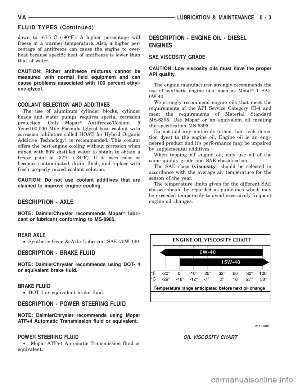
The SAE class(viscosity)should be selected in
accordance with the average air temperature for the
season of the year.
The temperature limits given for the different SAE
classes should be regarded as guidelines which may
be exceeded temporarily to avoid excessively frequent
engine oil changes.
OIL VISCOSITY CHART
VALUBRICATION & MAINTENANCE 0 - 3
FLUID TYPES (Continued)
Page 18 of 1232
MAINTENANCE - WITH ASSYST MAINTENANCE
COMPUTER
ASSYST provides information on the best possible
timing for maintenance work.
NOTE: The engine manufacturer strongly recom-
mends the use of synthetic engine oils, such as
TMobil 1 SAE 0W-40.
When the next maintenance service is due, this
will be indicated in the multi-function display with
the wrench icon symbol displayed in km/miles or
days.
²One wrench icon showing indicates Oil Service
is necessary.
²Two wrench icons showing indicates Mainte-
nance Service is necessary ± displayed in km/miles or
days.
If the display shows the number of days, a clock
symbol will also appear in the multi-function display.
You should have the maintenance performed
within the stated period/distance.
The service indicator should be reset after an oil
service and/or maintenance service has been per-
formed.
REGULAR CHECK-UPS
To maintain the safe operation of the vehicle, it is
recommended that the following tasks be performed
on a regular basis (i.e. weekly or whenever the vehi-
cle is refueled). Check:
²Engine oil level
²Brake system, clutch mechanism ± fluid level
²Battery ± acid level
²Windshield washer system and headlamp clean-
ing system ± fluid level
²Mechanical assemblies (e. g. engine, transmis-
sion, etc.) ± check for leaks
²Condition of tires and tires pressures
²All exterior lights
SPECIAL MAINTENANCE REQUIREMENTS
If bodies built by manufacturers other than
DaimlerChrysler Corporation are fitted to the vehi-
cle, the maintenance requirements and lubrication
intervals specified by the body manufacturer must be
adhered to, in addition to all standard maintenance
requirements.
Brake Fluid
Only use brake fluids approved by the manufac-
turer (DOT 4 plus).
Coolant
Corrosion inhibitor/antifreeze concentration in the
coolant should be checked before the onset of winter
(once year in countries with high prevailing temper-
atures).Replace the coolant every five years or 100,000
miles.
Dust Filter for Heating/Ventilation Replace-
ment
The dust filter and the tailgate interior filter are to
be renewed during routine maintenance service. If
operating conditions are dusty, these filters should be
renewed more frequently.
ENGINE OIL CHANGE AND FILTER REPLACEMENT
At the minimum, change the engine oil and oil fil-
ter once a year ± even if the vehicle mileage per year
is extremely low. For standard oil service schedules
refer to the chapter oil service and maintenance ser-
vice.
Once a Year
Select the viscosity of the engine oil (SAE classes)
according to the outside air temperature.
Only use engine oil approved by DaimlerChrysler
Corporation if following the ASSYST system guide-
lines.
If the fuel used has a sulphur content exceeding
0.05% by weight, the service intervals should be split
in half.
SCOPE OF WORK FOR MAINTENANCE SERVICE
Oil Service
²Engine:
Oil change and filter replacement
Check fluid levels of the following system,
refill as necessary.
²If fluid is lost, trace and eliminate cause ± as a
separate order.
²Power-assisted steering
Lubrication work:
²Trailer tow hitch (original equipment)
Maintenance
²ASSYST maintenance computer reset
Function check
²Signalling system, warning and indicator lamps
²Headlamps, exterior lighting
²Windshield wipers, windshield washer system
Check for leaks and damage.
²Check for abrasion points and ensure that lines
are correctly routed!
²All lines and hoses, sensor cables
²Rubber boots on front axle drive shafts, rubber
boots on front axle suspension ball joints, shock
absorbers
Check fluid levels for the following systems,
correct as necessary.
NOTE: Should there be a loss of fluid which cannot
be explained by regular use, trace and eliminate the
cause.
0 - 8 LUBRICATION & MAINTENANCEVA
MAINTENANCE SCHEDULES (Continued)
Page 19 of 1232
²Engine cooling system. Check corrosion inhibi-
tor/antifreeze, refill as necessary.
²Hydraulic brake system
²Battery
²Windshield washer system
Engine
²Fuel filter renewal
²Air cleaner with maintenance indicator:
²Check degree of contamination.
²Air cleaner filter element renewed as necessary.
Chassis and body
²Trailer coupling:
Check operation, play and retaining fixtures
²Secondary rubber springs:
Visual check
²Tire pressures:
Correct as necessary, including spare tire
²Check thickness of brake pads
²Brake test
²Check condition of steering mechanism
²Heating/ventilation dust filter renewal
ADDITIONAL MAINTENANCE WORK
Automatic transmission once only at 80,000
miles/128000 km
Oil and filter change
During every second maintenance service
Air cleaner without maintenance indicator:
Air cleaner filter element renewal
Check poly-V-belt for wear and signs of damage
During every 6th maintenance service
Rear axle
ADDITIONAL MAINTENANCE WORK AFTER YEARS
Every 3 years
Air cleaner filter element renewal (note installa-
tion date)
Every 5 years or 100,000 miles
Coolant renewal
Note coolant composition
INTERNATIONAL SYMBOLS
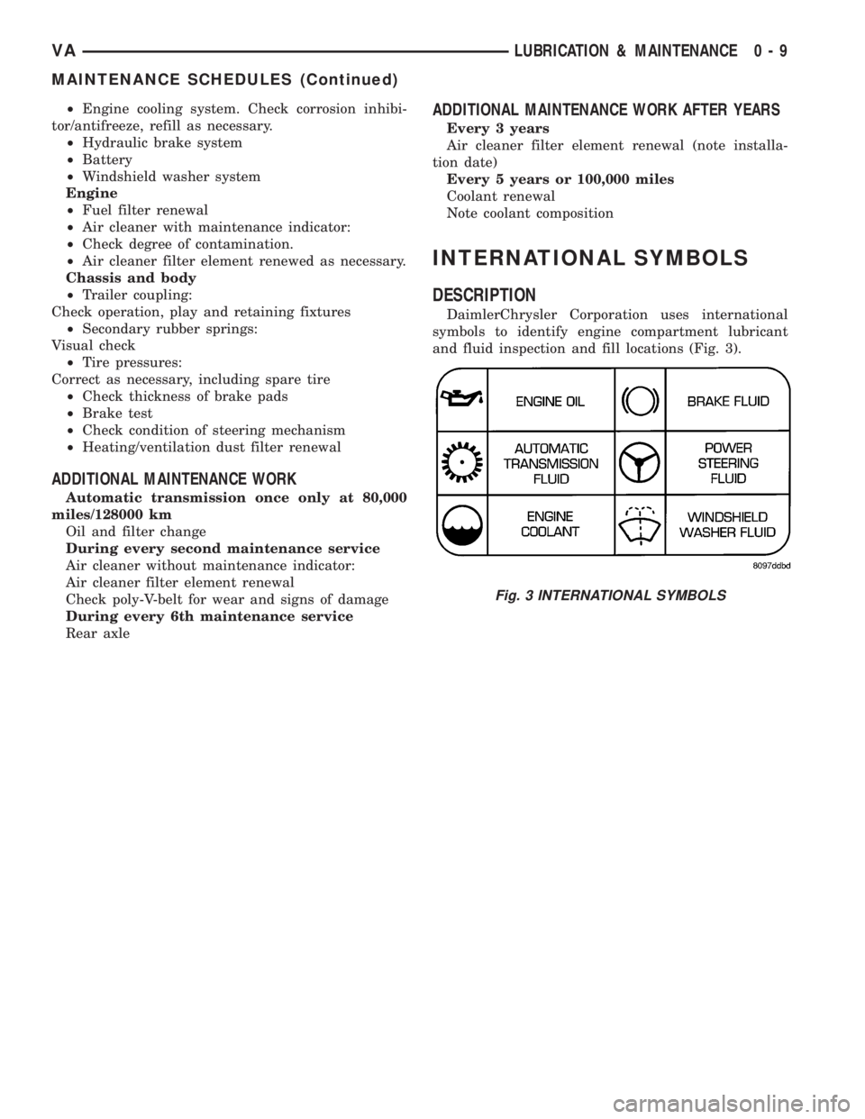
DESCRIPTION
DaimlerChrysler Corporation uses international
symbols to identify engine compartment lubricant
and fluid inspection and fill locations (Fig. 3).
Fig. 3 INTERNATIONAL SYMBOLS
VALUBRICATION & MAINTENANCE 0 - 9
MAINTENANCE SCHEDULES (Continued)
Page 51 of 1232
heard during a coast, the front pinion bearing is the
source.
Differential bearings usually produce a low pitch
noise. Differential bearing noise is similar to pinion
bearing noise. The pitch of differential bearing noise
is also constant and varies only with vehicle speed.
Axle shaft bearingsproduce noise and vibration
when worn or damaged. The noise generally changes
when the bearings are loaded. Road test the vehicle.
Turn the vehicle sharply to the left and to the right.
This will load the bearings and change the noise
level. Where axle bearing damage is slight, the noise
is usually not noticeable at speeds above 30 mph.
LOW SPEED KNOCK
Low speed knock is generally caused by a worn
U-joint or by worn side-gear thrust washers. A worn
pinion shaft bore will also cause low speed knock.
VIBRATION
Vibration at the rear of the vehicle is usually
caused by a:
²Damaged drive shaft.
²Missing drive shaft balance weight(s).
²Worn or out-of-balance wheels.
²Loose wheel lug nuts.
²Worn U-joint(s).
²Loose/broken springs.
²Damaged axle shaft bearing(s).
²Loose pinion gear nut.
²Excessive pinion yoke run out.
²Bent axle shaft(s).
Check for loose or damaged front-end components
or engine/transmission mounts. These components
can contribute to what appears to be a rearend vibra-
tion. Do not overlook engine accessories, brackets
and drive belts.
NOTE: All driveline components should be exam-
ined before starting any repair.
DRIVELINE SNAP
A snap or clunk noise when the vehicle is shifted
into gear (or the clutch engaged), can be caused by:
²High engine idle speed.
²Transmission shift operation.
²Loose engine/transmission/transfer case mounts.
²Worn U-joints.
²Loose spring mounts.
²Loose pinion gear nut and yoke.
²Excessive ring gear backlash.
²Excessive side gear to case clearance.
The source of a snap or a clunk noise can be deter-
mined with the assistance of a helper. Raise the vehi-
cle on a hoist with the wheels free to rotate. Instruct
the helper to shift the transmission into gear. Listenfor the noise, a mechanics stethoscope is helpful in
isolating the source of a noise.
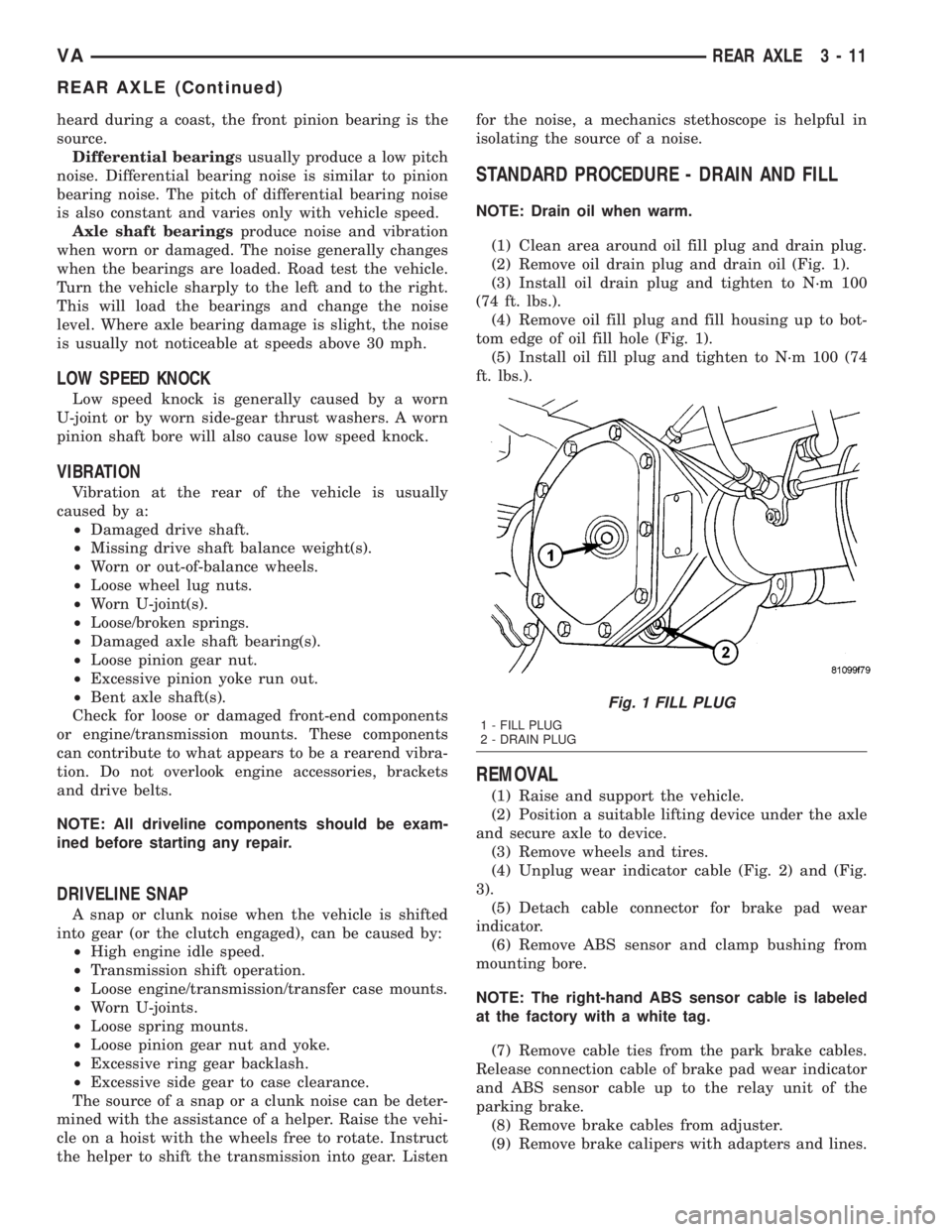
STANDARD PROCEDURE - DRAIN AND FILL
NOTE: Drain oil when warm.
(1) Clean area around oil fill plug and drain plug.
(2) Remove oil drain plug and drain oil (Fig. 1).
(3) Install oil drain plug and tighten to N´m 100
(74 ft. lbs.).
(4) Remove oil fill plug and fill housing up to bot-
tom edge of oil fill hole (Fig. 1).
(5) Install oil fill plug and tighten to N´m 100 (74
ft. lbs.).
REMOVAL
(1) Raise and support the vehicle.
(2) Position a suitable lifting device under the axle
and secure axle to device.
(3) Remove wheels and tires.
(4) Unplug wear indicator cable (Fig. 2) and (Fig.
3).
(5) Detach cable connector for brake pad wear
indicator.
(6) Remove ABS sensor and clamp bushing from
mounting bore.
NOTE: The right-hand ABS sensor cable is labeled
at the factory with a white tag.
(7) Remove cable ties from the park brake cables.
Release connection cable of brake pad wear indicator
and ABS sensor cable up to the relay unit of the
parking brake.
(8) Remove brake cables from adjuster.
(9) Remove brake calipers with adapters and lines.
Fig. 1 FILL PLUG
1 - FILL PLUG
2 - DRAIN PLUG
VAREAR AXLE 3 - 11
REAR AXLE (Continued)
Page 68 of 1232
A worn, damaged wheel bearing or suspension
component are further causes of pull. A damaged
front tire (bruised, ply separation) can also cause
pull.
A common and frequently misdiagnosed pull condi-
tion is where direction of pull changes after a few
stops. The cause is a combination of brake drag fol-
lowed by fade at one of the brake units.
As the dragging brake overheats, efficiency is so
reduced that fade occurs. Since the opposite brake
unit is still functioning normally, its braking effect is
magnified. This causes pull to switch direction in
favor of the normally functioning brake unit.
An additional point when diagnosing a change in
pull condition concerns brake cool down. Remember
that pull will return to the original direction, if the
dragging brake unit is allowed to cool down (and is
not seriously damaged).
REAR BRAKE GRAB OR PULL
Rear grab or pull is usually caused by improperly
adjusted or seized parking brake cables, contami-
nated lining, bent or binding shoes and support
plates, or improperly assembled components. This is
particularly true when only one rear wheel is
involved. However, when both rear wheels are
affected, the master cylinder or proportioning valve
could be at fault.
BRAKES DO NOT HOLD AFTER DRIVING THROUGH DEEP
WATER PUDDLES
This condition is generally caused by water soaked
lining. If the lining is only wet, it can be dried by
driving with the brakes very lightly applied for a
mile or two. However, if the lining is both soaked and
dirt contaminated, cleaning and/or replacement will
be necessary.
BRAKE LINING CONTAMINATION
Brake lining contamination is mostly a product of
leaking calipers or worn seals, driving through deep
water puddles, or lining that has become covered
with grease and grit during repair. Contaminated lin-
ing should be replaced to avoid further brake prob-
lems.
WHEEL AND TIRE PROBLEMS
Some conditions attributed to brake components
may actually be caused by a wheel or tire problem.
A damaged wheel can cause shudder, vibration and
pull. A worn or damaged tire can also cause pull.
Severely worn tires with very little tread left can
produce a grab-like condition as the tire loses and
recovers traction. Flat-spotted tires can cause vibra-
tion and generate shudder during brake operation. A
tire with internal damage such as a severe bruise,
cut, or ply separation can cause pull and vibration.BRAKE NOISES
Some brake noise is common with rear drum
brakes and on some disc brakes during the first few
stops after a vehicle has been parked overnight or
stored. This is primarily due to the formation of trace
corrosion (light rust) on metal surfaces. This light
corrosion is typically cleared from the metal surfaces
after a few brake applications causing the noise to
subside.
BRAKE SQUEAK/SQUEAL
Brake squeak or squeal may be due to linings that
are wet or contaminated with brake fluid, grease, or
oil. Glazed linings and rotors with hard spots can
also contribute to squeak. Dirt and foreign material
embedded in the brake lining will also cause squeak/
squeal.
A very loud squeak or squeal is frequently a sign of
severely worn brake lining. If the lining has worn
through to the brake pads in spots, metal-to-metal
contact occurs. If the condition is allowed to continue,
rotors can become so scored that replacement is nec-
essary.
BRAKE CHATTER
Brake chatter is usually caused by loose or worn
components, or glazed/burnt lining. Rotors with hard
spots can also contribute to chatter. Additional causes
of chatter are out-of-tolerance rotors, brake lining not
securely attached to the shoes, loose wheel bearings
and contaminated brake lining.
THUMP/CLUNK NOISE
Thumping or clunk noises during braking are fre-
quentlynotcaused by brake components. In many
cases, such noises are caused by loose or damaged
steering, suspension, or engine components. However,
calipers that bind on the slide surfaces can generate
a thump or clunk noise.
STANDARD PROCEDURE
STANDARD PROCEDURE - MANUAL BLEEDING
Use Mopar brake fluid, or an equivalent quality
fluid meeting SAE and DOT 4 standards only. Use
fresh, clean fluid from a sealed container at all times.
(1) Remove reservoir filler caps and fill reservoir.
(2) If calipers, or wheel cylinders were overhauled,
open all caliper and wheel cylinder bleed screws.
Then close each bleed screw as fluid starts to drip
from it. Top off master cylinder reservoir once more
before proceeding.
(3) Attach one end of bleed hose to bleed screw
and insert opposite end in glass container partially
filled with brake fluid (Fig. 1). Be sure end of bleed
hose is immersed in fluid.
5 - 4 BRAKES - BASEVA
BRAKES - BASE (Continued)
Page 175 of 1232
The EMIC modules for this model are serviced only
as complete units. The EMIC module cannot be
adjusted or repaired. If a gauge, an LED indicator,
the multi-fuction indicator LCD unit, an electronic
tone generator, the electronic circuit board, the cir-
cuit board hardware, the cluster overlay, the cluster
housing, the cluster hood, the cluster lens, or the
cluster rear cover are damaged or faulty, the entire
EMIC module must be replaced.
OPERATION
The ElectroMechanical Instrument Cluster (EMIC)
is designed to allow the vehicle operator to monitor
the conditions of many of the vehicle components and
operating systems. The gauges, meters and indicators
in the EMIC provide valuable information about the
powertrain, fuel and emissions systems, cooling sys-
tem, lighting systems, safety systems and many
other convenience items. The EMIC is installed in
the instrument panel so that all of these monitors
can be easily viewed by the vehicle operator when
driving, while still allowing relative ease of access for
service. The microprocessor-based EMIC hardware
and software uses various inputs to control the
gauges and indicators visible on the face of the clus-
ter. Some of these inputs are hard wired, but many
are in the form of electronic messages that are trans-
mitted by other electronic modules over the Control-
ler Area Network (CAN) data bus network. (Refer to
8 - ELECTRICAL/ELECTRONIC CONTROL MOD-
ULES/COMMUNICATION - OPERATION).
The EMIC microprocessor smooths the input data
using algorithms to provide gauge readings that are
accurate, stable and responsive to operating condi-
tions. These algorithms are designed to provide
gauge readings during normal operation that are con-
sistent with customer expectations. However, when
abnormal conditions exist such as high coolant tem-
perature, the algorithm can drive the gauge pointer
to an extreme position and the microprocessor can
sound a chime through the on-board audible tone
generator to provide distinct visual and audible indi-
cations of a problem to the vehicle operator. The
instrument cluster circuitry also provides audible
turn signal and hazard warning support by emulat-
ing the ªtickingº sound associated with a conven-
tional electro-mechanical flasher using a contactless
relay. The relay will also provide an indication of a
turn signal failure by sounding at double the usual
frequency. Each audible warning is provided to the
vehicle operator to supplement a visual indication.
The EMIC circuitry operates on battery current
received through a non-switched fused B(+) circuit,
and on a fused ignition switch output circuit. The
EMIC circuitry is grounded through a ground circuit
and take out of the frame wire harness with an eye-let terminal connector that is secured to a stud by a
nut at a ground location on the dash panel just for-
ward of the instrument cluster. Separate switched
ground inputs from the key-in ignition switch and
the front door jamb switches provide wake-up signals
to the EMIC circuitry. This arrangement allows the
EMIC to provide some features regardless of the igni-
tion switch position, while other features will operate
only with the ignition switch in the On position.
Proper diagnosis and testing of the EMIC, the
CAN data bus, the data bus electronic message
inputs to and outputs from the EMIC, as well as the
retrieval or erasure of a Diagnostic Trouble Code
(DTC) requires the use of a DRBIIItscan tool. Refer
to the appropriate diagnostic information. See the
owner's manual in the vehicle glove box for more
information on the features, use and operation of the
EMIC.
GAUGES
All gauges receive battery current through the
EMIC circuitry only when the instrument cluster
detects the ignition switch is in the On position. With
the ignition switch in the Off position, battery cur-
rent is not supplied to any gauges and the EMIC cir-
cuitry is programmed to move all of the gauge
needles back to the low end of their respective scales.
Therefore, the gauges do not accurately indicate any
vehicle condition unless the ignition switch is in the
On position.
All of the EMIC gauges are air core magnetic
units. Two fixed electromagnetic coils are located
within each gauge. These coils are wrapped at right
angles to each other around a movable permanent
magnet. The movable magnet is suspended within
the coils on one end of a pivot shaft, while the gauge
needle is attached to the other end of the shaft. One
of the coils has a fixed current flowing through it to
maintain a constant magnetic field strength. Current
flow through the second coil changes, which causes
changes in its magnetic field strength. The current
flowing through the second coil is changed by the
EMIC circuitry in response to messages received over
the CAN data bus. The gauge needle moves as the
movable permanent magnet aligns itself to the
changing magnetic fields created around it by the
electromagnets.
Proper diagnosis and testing of the gauges, the
CAN data bus and the electronic data bus message
inputs to the EMIC that control each gauge require
the use of a DRBIIItscan tool. Refer to the appro-
priate diagnostic information. Specific operation
details for each gauge may be found elsewhere in
this service information.
VAINSTRUMENT CLUSTER 8J - 5
INSTRUMENT CLUSTER (Continued)
Page 188 of 1232
²High Beams On Input- Each time the cluster
receives a high beam headlamps-on input from the
multi-function switch, the high beam indicator will
be illuminated. The indicator remains illuminated
until the cluster receives a high beam headlamps-off
input from the multi-function switch.
The instrument cluster continually monitors the
multi-function switch input to determine whether the
high beam indicator should be illuminated or extin-
guished. The multi-function switch and the multi-
function switch input circuit to the instrument
cluster can be diagnosed using conventional diagnos-
tic tools and methods. For proper diagnosis of the
instrument cluster circuitry that controls the high
beam indicator, a DRBIIItscan tool is required.
Refer to the appropriate diagnostic information.
LOW FUEL INDICATOR
DESCRIPTION
A low fuel indicator is standard equipment on all
instrument clusters. The low fuel indicator is located
directly below the low end of the fuel gauge scale.
The low fuel indicator consists of a small triangular
cutout in the opaque layer of the instrument cluster
overlay. The dark outer layer of the overlay prevents
the indicator from being clearly visible when it is not
illuminated. An amber Light Emitting Diode (LED)
behind the cutout in the opaque layer of the overlay
causes the triangle to appear in amber through the
translucent outer layer of the overlay when the indi-
cator is illuminated from behind by the LED, which
is soldered onto the instrument cluster electronic cir-
cuit board. The low fuel indicator is serviced as a
unit with the instrument cluster.
OPERATION
The low fuel indicator gives an indication to the
vehicle operator when the level of fuel in the fuel
tank becomes low. This indicator is controlled by a
transistor on the instrument cluster circuit board
based upon cluster programming and a hard wired
input received by the cluster from the fuel level sen-
sor in the fuel tank. The low fuel indicator Light
Emitting Diode (LED) is completely controlled by the
instrument cluster logic circuit, and that logic will
only allow this indicator to operate when the instru-
ment cluster detects that the ignition switch is in the
On position. Therefore, the LED will always be off
when the ignition switch is in any position except
On. The LED only illuminates when it is provided a
path to ground by the instrument cluster transistor.
The instrument cluster will turn on the low fuel indi-
cator for the following reasons:²Bulb Test- Each time the ignition switch is
turned to the On position the low fuel indicator is
illuminated for about two seconds as a bulb test.
²Fuel Level Sensor Input- Each time the clus-
ter receives an input from the fuel level sensor indi-
cating that the fuel level has reached about 12 liters
(3 gallons) or less, the low fuel indicator is illumi-
nated. The indicator remains illuminated until the
cluster receives an input from the fuel level sensor
indicating that the fuel level is above 12 liters (3 gal-
lons), or until the ignition switch is turned to the Off
position, whichever occurs first.
The fuel level sensor in the fuel tank provides a
hard wired input to the instrument cluster circuitry
through the fuel level sense circuit. The fuel level
sensor is a potentiometer that changes resistance
according to the fuel level. As the fuel level
decreases, the resistance through the fuel level sen-
sor increases. The fuel level sensor and the fuel level
sense circuit to the instrument cluster can be diag-
nosed using conventional diagnostic tools and meth-
ods. For proper diagnosis of the instrument cluster
circuitry that controls the fuel gauge, a DRBIIItscan
tool is required. Refer to the appropriate diagnostic
information.
LOW OIL LEVEL INDICATOR
DESCRIPTION
A low oil level indicator is standard equipment on
all instrument clusters. The low oil level indicator is
located near the lower edge of the instrument cluster,
to the left of the multi-function indicator display. The
low oil level indicator consists of the International
Control and Display Symbol icon for ªEngine Oilº
imprinted within a rectangular cutout in the opaque
layer of the instrument cluster overlay. The dark
outer layer of the overlay prevents the indicator from
being clearly visible when it is not illuminated. A red
Light Emitting Diode (LED) behind the cutout in the
opaque layer of the overlay causes the icon to appear
silhouetted against a red field through the translu-
cent outer layer of the overlay when the indicator is
illuminated from behind by the LED, which is sol-
dered onto the instrument cluster electronic circuit
board. The low oil level indicator is serviced as a unit
with the instrument cluster.
OPERATION
The low oil level indicator gives an indication to
the vehicle operator when the engine oil level is low.
This indicator is controlled by a transistor on the
instrument cluster electronic circuit board based
upon cluster programming and electronic messages
received by the cluster from the Engine Control Mod-
8J - 18 INSTRUMENT CLUSTERVA
HIGH BEAM INDICATOR (Continued)
Page 191 of 1232
OPERATION
The multi-function indicator has several display
capabilities including odometer, trip odometer, clock,
engine oil level data, gear selector indicator
(PRNDL), certain diagnostic information and, on
vehicles so equipped, an optional Active Service SYS-
Tem (ASSYST) engine oil maintenance indicator and
an optional outside ambient temperature indicator.
The multi-function indicator is completely controlled
by the instrument cluster logic circuit, and that logic
will allow this indication to be viewed whenever the
multi-function indicator Liquid Crystal Display
(LCD) is activated. Therefore, the indicator remains
functional regardless of the ignition switch position.
With the ignition switch in the Off or Accessory posi-
tions and the key removed from the ignition lock cyl-
inder, the display is activated when the park lamps
are turned On or, for about thirty seconds after any
one of the multi-function indicator switch push but-
tons is depressed. Otherwise, the display unit is
active for about thirty seconds after the key is
inserted into the ignition lock cylinder, and inactive
about thirty seconds after the key is removed from
the ignition lock cylinder.
The multi-function indicator ªmiº (miles) or
ªkmº(kilometers) switch push button is used to con-
trol the odometer/trip odometer display modes. The
multi-function indicator clock switch push button is
used to control the clock/outside temperature display
modes. The multi-function indicator ª+º (plus) and
ª2º (minus) switch push buttons are used to adjust
the cluster general illumination dimming level, the
clock, and other cluster settings. See the owner's
manual in the vehicle glove box for more information
on the features, use, operation and setting proce-
dures for the various standard and optional multi-
function indicator displays.
Proper testing of the multi-function indicator LCD
unit, the CAN data bus and the electronic data bus
message inputs to the instrument cluster that control
some of the multi-function indicator functions
requires the use of a DRBIIItscan tool. Refer to the
appropriate diagnostic information. Additional details
for the odometer/trip odometer, the clock, the gear
selector indicator, the ambient temperature indicator
and the ASSYST warning and reminder functions of
the multi-function indicator may be found elsewhere
in this service information.
ODOMETER
DESCRIPTION
An odometer and trip odometer are standard
equipment in all instrument clusters. The odometer
and trip odometer values are displayed on the leftside of the multi-function indicator Liquid Crystal
Display (LCD). The LCD is soldered onto the cluster
electronic circuit board and is visible through a win-
dow with a clear lens located near the lower edge of
the instrument cluster, directly below the speedome-
ter. However, the odometer and trip odometer infor-
mation are not displayed simultaneously. The ªmiº
(miles) or ªkmº (kilometers) switch on the instrument
cluster circuit board toggles the display between
odometer and trip odometer modes by depressing the
switch push button that extends through the lower
edge of the cluster lens, directly below the multi-
function indicator LCD.
The odometer and trip odometer information is
stored in the instrument cluster memory. This infor-
mation can be increased when the proper inputs are
provided to the instrument cluster, but the informa-
tion cannot be decreased. The odometer can display
values up to 999,999 kilometers (999,999 miles). The
odometer latches at these values, and will not roll
over to zero. The trip odometer can display values up
to 999.9 kilometers (999.9 miles) before it rolls over
to zero. The odometer display does not have a deci-
mal point and will not show values less than a full
unit (kilometer or mile), while the trip odometer dis-
play does have a decimal point and will show tenths
of a unit (kilometer or mile). The unit of measure
(kilometers or miles) for the odometer and trip odom-
eter display is imprinted on the cluster overlay below
the left end of the LCD. The unit of measure for the
instrument cluster odometer/trip odometer is selected
at the time that it is manufactured, and cannot be
changed.
The indications of the odometer/trip odometer are
not visible when the LCD is not illuminated. When
illuminated the indications appear as dark charac-
ters silhouetted against an amber field. When the
exterior lighting is turned Off, the display is illumi-
nated at maximum brightness. When the exterior
lighting is turned On the display illumination level
can be adjusted in concert with the cluster general
illumination lighting using the plus and minus multi-
function indicator push buttons. The odometer has a
ªRental Carº mode, which will activate the multi-
function indicator LCD and illuminate the odometer
information for about thirty seconds after one of the
multi-function indicator push buttons is momentarily
depressed, or after the key is inserted into the igni-
tion switch lock cylinder with the ignition switch in
the Off position.
The odometer/trip odometer and the miles/kilome-
ters switch, and the miles/kilometers switch push
button are serviced as a unit with the instrument
cluster.
VAINSTRUMENT CLUSTER 8J - 21
MULTI-FUNCTION INDICATOR (Continued)