2005 MERCEDES-BENZ SPRINTER roof rack
[x] Cancel search: roof rackPage 200 of 1232

REAR SIDE MARKER LAMP BULB
REMOVAL.............................21
INSTALLATION.........................21
REAR TURN LAMP BULB
REMOVAL.............................21
INSTALLATION.........................22
REPEATER LAMP BULB
REMOVAL.............................22
INSTALLATION.........................22REPEATER LAMP UNIT
REMOVAL.............................22
INSTALLATION.........................23
TAIL LAMP UNIT
REMOVAL.............................23
INSTALLATION.........................23
TURN SIGNAL RELAY
REMOVAL.............................24
INSTALLATION.........................24
LAMPS/LIGHTING - EXTERIOR
DESCRIPTION
The exterior lighting system for this model
includes the following exterior lamps:
²Backup Lamps- The backup (or reverse) lamps
are integral to the tail lamp units mounted to the
back of the quarter panel on each side of the tailgate
at the rear of the vehicle.
²Brake Lamps- The brake (or stop) lamps
include a bulb and reflector that are integral to the
tail lamp units mounted to the back of the quarter
panel on each side of the tailgate opening, and the
Center High Mounted Stop Lamp (CHMSL) that is
centered on the rear edge of the roof panel above the
tailgate opening.
²Daytime Running Lamps- Vehicles manufac-
tured for sale in Canada have a Daytime Running
Lamps (DRL) relay that illuminates the low beam
headlamp bulbs whenever the engine is running.
²Fog Lamps- Fog lamp bulbs and reflectors are
included in both front lamp units of vehicles
equipped with this option.
²Hazard Warning Lamps- The hazard warning
lamps include all of the right and left turn signal and
repeater lamps.
²Headlamps- Separate low beam and high
beam headlamp bulbs are installed in the front lamp
unit on each side of the front grille opening. A head-
lamp leveling actuator motor is also integral to each
front lamp unit.
²Park Lamps- The park lamps include the front
park/side marker lamps and front position lamps
that are integral to the front lamp units mounted on
either side of the front grille opening, as well as the
rear park lamps and rear side marker lamps that are
integral to the tail lamp units mounted to the back of
the quarter panel on each side of the tailgate open-
ing. Included in the park lamps circuit are two rear
license plate lamp units mounted on the left rear
tailgate door. The park lamps may also include
optional clearance lamps, which are located on each
side of a vehicle that is so equipped.
²Turn Signal Lamps- The turn signal lamps
include the front turn lamps that are integral to the
front lamp units, the rear turn lamps that are inte-
gral to the tail lamp units, and a repeater lampmounted to each front fender just above the front
wheel opening.
Other components of the exterior lighting system
for this model include:
²Brake Lamp Switch- A plunger-type brake
lamp switch is located on the steering column sup-
port bracket under the instrument panel and actu-
ated by the brake pedal arm.
²Daytime Running Lamp Relays- Vehicles
manufactured for sale in Canada have two Daytime
Running Lamps (DRL) relays. Dedicated right and
left side relays illuminate the low beam headlamp
bulb installed in each front lamp unit whenever the
engine is running. These relays are located in dedi-
cated vehicle wire harness connectors within the
driver side front seat riser.
²Fog Lamp Relay- Vehicles equipped with the
optional fog lamps have a fog lamp relay located in a
dedicated vehicle wire harness connector within the
driver side front seat riser.
²Fog Lamp Switch- A fog lamp switch is
mounted in the instrument cluster bezel, below the
cluster and outboard of the steering column on vehi-
cles equipped with this option.
²Headlamp Leveling Motor- A headlamp lev-
eling actuator motor is located on the back of each
headlamp housing and adjusts both the low beam
headlamp, high beam headlamp, and fog lamp (if
equipped) reflector frames in unison.
²Headlamp Leveling Switch- A thumbwheel
actuated headlamp leveling switch is mounted in the
instrument cluster bezel, below the cluster and out-
board of the steering column.
²Multi-Function Switch- The multi-function
switch is located on the top of the steering column,
just below the steering wheel. The multi-function
switch is connected directly to the fuse block located
below the steering column through an integral inter-
face connector. Only the left (lighting), right (wiper)
control stalks and the hazard warning switch button
for the multi-function switch are visible, the remain-
der of the switch is concealed beneath the steering
column shrouds. The multi-function switch includes a
left (lighting) control stalk and a right (wiper) control
stalk. The left control stalk is dedicated to providing
almost all of the driver controls for the exterior light-
ing system.
8L - 2 LAMPS/LIGHTING - EXTERIORVA
Page 1082 of 1232

INSTALLATION
(1) Install the door by inserting the center and
upper rollers into the tracks and sliding the door for-
ward to the front of each track.
(2) Connect the lower roller arm and install the
screws.
(3) Tighten the screws to 25 N´m (18 ft. lbs.).
(4) Install door stop and screws.
(5) Tighten the screws to 10 N´m (89 in. lbs.).
(6) Install the center track end piece and install
the screw.
(7) Tighten the screw to 10 N´m (89 in. lbs.).
(8) Check and adjust door if necessary. (Refer to 23
- BODY/DOORS - SLIDING/SLIDING DOOR -
ADJUSTMENTS)
(9) Connect battery negative cable.
ADJUSTMENTS
ADJUSTMENT
NOTE: Door adjustment measurements should be
taken from stationary or welded body panels like
the roof, rocker or quarter panels.
A suitable body sealant should be used when
removing or moving the hinges.
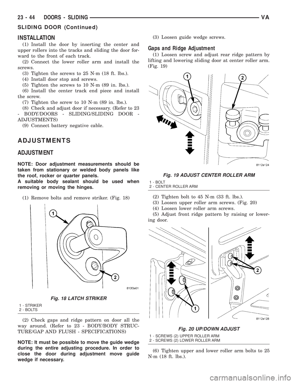
(1) Remove bolts and remove striker. (Fig. 18)
(2) Check gaps and ridge pattern on door all the
way around. (Refer to 23 - BODY/BODY STRUC-
TURE/GAP AND FLUSH - SPECIFICATIONS)
NOTE: It must be possible to move the guide wedge
during the entire adjusting procedure. In order to
close the door during adjustment move guide
wedge if necessary.(3) Loosen guide wedge screws.
Gaps and Ridge Adjustment
(1) Loosen screw and adjust rear ridge pattern by
lifting and lowering sliding door at center roller arm.
(Fig. 19)
(2) Tighten bolt to 45 N´m (33 ft. lbs.).
(3) Loosen upper roller arm screws. (Fig. 20)
(4) Loosen lower roller arm screws.
(5) Adjust front ridge pattern by raising or lower-
ing door.
(6) Tighten upper and lower roller arm bolts to 25
N´m (18 ft. lbs.).
Fig. 18 LATCH STRIKER
1 - STRIKER
2 - BOLTS
Fig. 19 ADJUST CENTER ROLLER ARM
1 - BOLT
2 - CENTER ROLLER ARM
Fig. 20 UP/DOWN ADJUST
1 - SCREWS (2) UPPER ROLLER ARM
2 - SCREWS (2) LOWER ROLLER ARM
23 - 44 DOORS - SLIDINGVA
SLIDING DOOR (Continued)
Page 1155 of 1232

SOLENOID VALVE
DESCRIPTION
The rear A/C solenoid valve is a two-position elec-
trically operated shut-off valve, which is used to con-
trol refrigerant flow to the rear A/C evaporator from
the A/C compressor. The solenoid valve is located in
the rear A/C evaporator housing and is attached by a
bracket.
OPERATION
The solenoid valve is used by the rear A/C control
module to control rear A/C output temperature and
to prevent evaporator freezing. Evaporator tempera-
ture is controlled by cycling the solenoid valve open
and closed, thereby controlling refrigerant flow to the
rear evaporator. The normally closed valve only
allows refrigerant to flow through it when power is
supplied to the solenoid by the rear A/C control mod-
ule.
DIAGNOSIS AND TESTING
For circuit descriptions and diagrams, refer to Air
Conditioning/Heater in Group 8W - Wiring Diagrams.
NOTE: Prior to performing the following checks,
verify that the front A/C system is operating prop-
erly.
(1) With the engine running, the front A/C switch
in the On position and the rear A/C blower switch in
the Off position, check that the rear evaporator is not
colder than the ambient temperature. If the evapora-
tor temperature is colder than the ambient tempera-
ture, the solenoid is allowing refrigerant to flow
through the rear evaporator when in the closed posi-
tion. If OK, go to Step 2. If not OK, replace the rear
A/C solenoid valve (Refer to 24 - HEATING & AIR
CONDITIONING/CONTROLS/SOLENOID - REMOV-
AL).
(2) With the ignition switch in the Off position and
the rear A/C solenoid valve wire harness discon-
nected, check for continuity between the two solenoid
valve terminals. If OK, go to Step 3. If not OK,
replace the solenoid valve (Refer to 24 - HEATING &
AIR CONDITIONING/CONTROLS/SOLENOID -
REMOVAL).
(3) With the ignition switch in the Off position and
the rear A/C solenoid valve wire harness discon-
nected, check the solenoid valve ground circuits for a
good ground at all times. If OK, go to Step 4. If not
OK, repair the open circuit to ground as required.(4) With the ignition switch and the front A/C
switch in the On position and the rear A/C solenoid
valve wire harness disconnected, check the harness
for battery power at terminal 2. If OK, replace the
solenoid valve (Refer to 24 - HEATING & AIR CON-
DITIONING/CONTROLS/SOLENOID - REMOVAL).
If not OK, test the A/C control module as required
(Refer to 24 - HEATING & AIR CONDITIONING/
CONTROLS/POWER MODULE - DIAGNOSIS AND
TESTING).
REMOVAL
(1) Recover the refrigerant from the refrigerant
system (Refer to 24 - HEATING & AIR CONDITION-
ING/PLUMBING - STANDARD PROCEDURE).
(2) Disconnect and isolate the battery negative
cable.
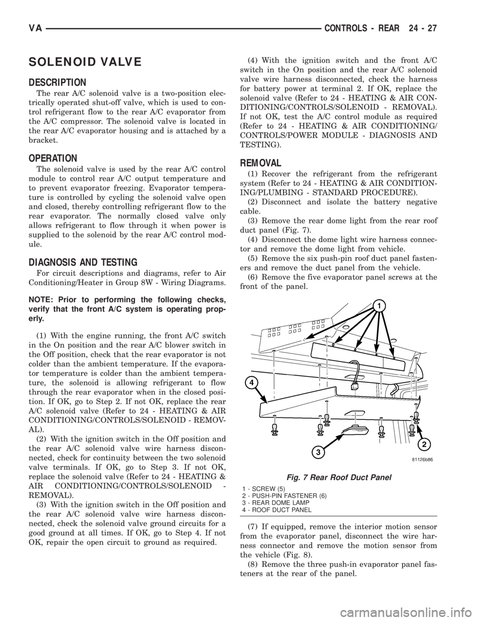
(3) Remove the rear dome light from the rear roof
duct panel (Fig. 7).
(4) Disconnect the dome light wire harness connec-
tor and remove the dome light from vehicle.
(5) Remove the six push-pin roof duct panel fasten-
ers and remove the duct panel from the vehicle.
(6) Remove the five evaporator panel screws at the
front of the panel.
(7) If equipped, remove the interior motion sensor
from the evaporator panel, disconnect the wire har-
ness connector and remove the motion sensor from
the vehicle (Fig. 8).
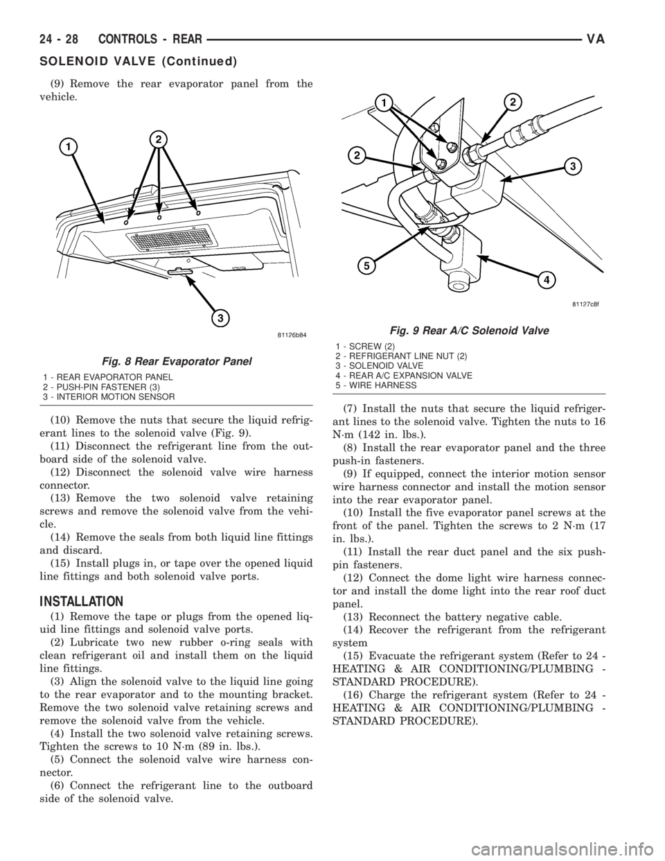
(8) Remove the three push-in evaporator panel fas-
teners at the rear of the panel.
Fig. 7 Rear Roof Duct Panel
1 - SCREW (5)
2 - PUSH-PIN FASTENER (6)
3 - REAR DOME LAMP
4 - ROOF DUCT PANEL
VACONTROLS - REAR 24 - 27
Page 1156 of 1232

(9) Remove the rear evaporator panel from the
vehicle.
(10) Remove the nuts that secure the liquid refrig-
erant lines to the solenoid valve (Fig. 9).
(11) Disconnect the refrigerant line from the out-
board side of the solenoid valve.
(12) Disconnect the solenoid valve wire harness
connector.
(13) Remove the two solenoid valve retaining
screws and remove the solenoid valve from the vehi-
cle.
(14) Remove the seals from both liquid line fittings
and discard.
(15) Install plugs in, or tape over the opened liquid
line fittings and both solenoid valve ports.
INSTALLATION
(1) Remove the tape or plugs from the opened liq-
uid line fittings and solenoid valve ports.
(2) Lubricate two new rubber o-ring seals with
clean refrigerant oil and install them on the liquid
line fittings.
(3) Align the solenoid valve to the liquid line going
to the rear evaporator and to the mounting bracket.
Remove the two solenoid valve retaining screws and
remove the solenoid valve from the vehicle.
(4) Install the two solenoid valve retaining screws.
Tighten the screws to 10 N´m (89 in. lbs.).
(5) Connect the solenoid valve wire harness con-
nector.
(6) Connect the refrigerant line to the outboard
side of the solenoid valve.(7) Install the nuts that secure the liquid refriger-
ant lines to the solenoid valve. Tighten the nuts to 16
N´m (142 in. lbs.).
(8) Install the rear evaporator panel and the three
push-in fasteners.
(9) If equipped, connect the interior motion sensor
wire harness connector and install the motion sensor
into the rear evaporator panel.
(10) Install the five evaporator panel screws at the
front of the panel. Tighten the screws to 2 N´m (17
in. lbs.).
(11) Install the rear duct panel and the six push-
pin fasteners.
(12) Connect the dome light wire harness connec-
tor and install the dome light into the rear roof duct
panel.
(13) Reconnect the battery negative cable.
(14) Recover the refrigerant from the refrigerant
system
(15) Evacuate the refrigerant system (Refer to 24 -
HEATING & AIR CONDITIONING/PLUMBING -
STANDARD PROCEDURE).
(16) Charge the refrigerant system (Refer to 24 -
HEATING & AIR CONDITIONING/PLUMBING -
STANDARD PROCEDURE).
Fig. 8 Rear Evaporator Panel
1 - REAR EVAPORATOR PANEL
2 - PUSH-PIN FASTENER (3)
3 - INTERIOR MOTION SENSOR
Fig. 9 Rear A/C Solenoid Valve
1 - SCREW (2)
2 - REFRIGERANT LINE NUT (2)
3 - SOLENOID VALVE
4 - REAR A/C EXPANSION VALVE
5 - WIRE HARNESS
24 - 28 CONTROLS - REARVA
SOLENOID VALVE (Continued)