2005 MERCEDES-BENZ SPRINTER driver seat adjustment
[x] Cancel search: driver seat adjustmentPage 80 of 1232

(8) Raise the vehicle and adjust the ALB controller
(Refer to 5 - BRAKES/HYDRAULIC/MECHANICAL/
ALB CONTROLLER - ADJUSTMENTS).
(9) Lower the vehicle and test drive.
ADJUSTMENTS
ADJUSTMENT
(1) Clean any debris away from the test ports caps
at the ALB controller.
(2) Connect brake adapters special tool 9297 to the
test ports at the ALB controller.
(3) Install a Pressure Gauge, Special Tool
C-4007-A, to the adapters.
(4) Tighten all tube nut fittings to 17 N´m (145 in.
lbs.) torque.
(5) Bleed any air out of the system. This includes
bleeding the air from the hose between the pressure
test fitting and pressure gauge, which is done at the
pressure gauge.
NOTE: Adjustment is determined for the automatic
load-dependent brake power control system accord-
ing to the ALB plate. This is housed in the stowage
compartment under the front passenger's door
panel. The part number of the rear spring is
stamped into the spring eye. This must correspond
to the part number of the rear spring on the ALB
plate.
(6) To accurately adjust the rear axle load you
must first determine the rear axle load by weighing
the vehicle at a local scale.
(7) Install the brake pedal winch Special tool 9296
between the brake pedal and the driver seat and
slowly turn the dial until the specified inlet brake
pressure is indicated at the gauge.
NOTE: The pressure gauge, connected at the ALB
controller must indicate the outlet pressure which
is assigned on the ALB plate to the rear axle load
determined.
NOTE: If the rear axle load determined is between
two figures indicated on the ALB plate, the outlet
pressure should be determined accordingly.
(8) If the pressure measured differs from the spec-
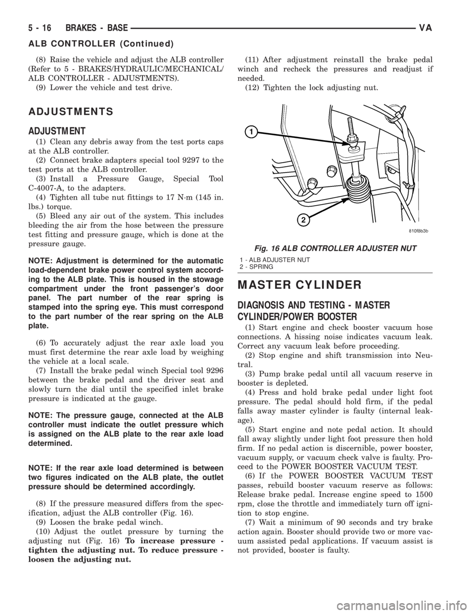
ification, adjust the ALB controller (Fig. 16).
(9) Loosen the brake pedal winch.
(10) Adjust the outlet pressure by turning the
adjusting nut (Fig. 16)To increase pressure -
tighten the adjusting nut. To reduce pressure -
loosen the adjusting nut.(11) After adjustment reinstall the brake pedal
winch and recheck the pressures and readjust if
needed.
(12) Tighten the lock adjusting nut.
MASTER CYLINDER
DIAGNOSIS AND TESTING - MASTER
CYLINDER/POWER BOOSTER
(1) Start engine and check booster vacuum hose
connections. A hissing noise indicates vacuum leak.
Correct any vacuum leak before proceeding.
(2) Stop engine and shift transmission into Neu-
tral.
(3) Pump brake pedal until all vacuum reserve in
booster is depleted.
(4) Press and hold brake pedal under light foot
pressure. The pedal should hold firm, if the pedal
falls away master cylinder is faulty (internal leak-
age).
(5) Start engine and note pedal action. It should
fall away slightly under light foot pressure then hold
firm. If no pedal action is discernible, power booster,
vacuum supply, or vacuum check valve is faulty. Pro-
ceed to the POWER BOOSTER VACUUM TEST.
(6) If the POWER BOOSTER VACUUM TEST
passes, rebuild booster vacuum reserve as follows:
Release brake pedal. Increase engine speed to 1500
rpm, close the throttle and immediately turn off igni-
tion to stop engine.
(7) Wait a minimum of 90 seconds and try brake
action again. Booster should provide two or more vac-
uum assisted pedal applications. If vacuum assist is
not provided, booster is faulty.
Fig. 16 ALB CONTROLLER ADJUSTER NUT
1 - ALB ADJUSTER NUT
2 - SPRING
5 - 16 BRAKES - BASEVA
ALB CONTROLLER (Continued)
Page 202 of 1232

FRONT FOG LAMPS
Vehicles equipped with optional front fog lamps
have a front fog lamp relay installed in a relay
bracket located below the forward edge of the driver
side front seat cushion within the driver side front
seat riser, a fog lamp switch installed in the cluster
bezel on the instrument panel outboard of the steer-
ing column, and a fog lamp bulb installed in each of
the two front lamp units. The front fog lamps have a
path to ground at all times through their connection
to the vehicle wire harness. The headlamp switch cir-
cuitry of the left (lighting) control stalk of the multi-
function switch controls front fog lamp operation by
providing battery current to the front fog lamp relay
only when the low beam headlamps are selected. The
fog lamp switch controls front fog lamp operation by
energizing or de-energizing the front fog lamp relay
control coil.
HAZARD WARNING LAMPS
With the hazard switch in the On position, the
hazard switch button illuminates and the right and
left turn signal indicators as well as the right and
left turn signal lamps begin to flash on and off. When
the hazard warning system is activated, the hazard
switch circuitry within the multi-function switch and
the wipers, turn signals and engine start control
module electronic circuitry within the fuse block will
repeatedly energize and de-energize the turn signal
relay located in the fuse block. The turn signal relay
switches battery current from a fused B(+) fuse in
the fuse block to the turn signal indicators and the
turn signal lamps. The flashing of the hazard switch
button illumination lamp is also controlled by the
output from the turn signal relay.
HEADLAMPS
The headlamp system includes the exterior lighting
switches integral to the left (lighting) control stalk of
the multi-function switch as well as the low and high
beam bulbs installed in the right and left front lamp
units (Fig. 1). The headlamp bulbs have a path to
ground at all times through the vehicle wire harness.
The exterior lighting switches control headlamp oper-
ation by providing battery current to the selected low
or high beam bulbs. Each front lamp unit includes
two integral adjustment screws to be used for static
horizontal and vertical aiming of the headlamp beam
reflectors.
HEADLAMP LEVELING
The headlamp leveling system includes a leveling
actuator motor integral to each front lamp unit, and
a rotary thumbwheel actuated headlamp leveling
switch in the cluster bezel on the instrument panel
outboard of the steering column. The headlamp lev-eling system allows the headlamp beam reflectors to
be adjusted to one of four vertical positions to com-
pensate for changes in inclination caused by the load-
ing of the vehicle suspension. The actuator motors
are mechanically connected through an integral
pushrod to an adjustable headlamp reflector. The
headlamp leveling switch is a resistor multiplexed
unit that provides one of four voltage outputs to the
headlamp leveling motors. The headlamp leveling
motors will move the headlamps to the selected posi-
tion based upon the voltage input received from the
switch. The headlamp leveling motors and switch
have a path to ground at all times. The headlamp
leveling components operate on battery current
received through the park lamps circuit so that the
system will only operate when the exterior lighting is
turned on.
PARK LAMPS
The park lamps system includes the exterior light-
ing switches integral to the left (lighting) control
stalk of the multi-function switch (Fig. 1), the front
park/side marker lamps, the front position lamps, the
rear park lamps, the rear side marker lamps, the
optional clearance lamps, and the license plate
lamps. Each of these lamps are provided with a path
to ground at all times through the vehicle wire har-
ness. The exterior lighting switches control the park
lamp operation by providing battery current through
the park lamps circuit to the appropriate lamp bulbs.
TURN SIGNAL LAMPS
When the left (lighting) control stalk of the multi-
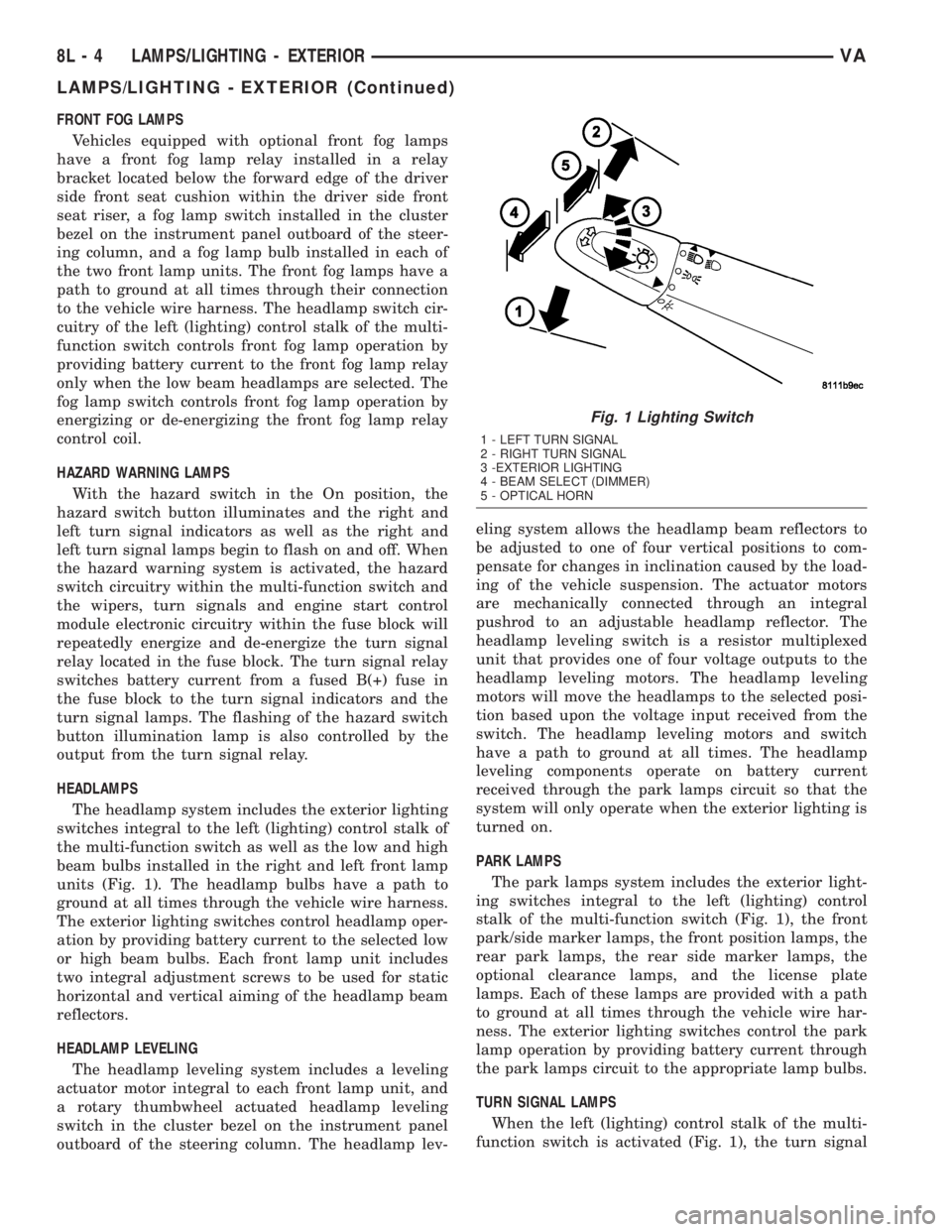
function switch is activated (Fig. 1), the turn signal
Fig. 1 Lighting Switch
1 - LEFT TURN SIGNAL
2 - RIGHT TURN SIGNAL
3 -EXTERIOR LIGHTING
4 - BEAM SELECT (DIMMER)
5 - OPTICAL HORN
8L - 4 LAMPS/LIGHTING - EXTERIORVA
LAMPS/LIGHTING - EXTERIOR (Continued)
Page 211 of 1232

(3) Repair or replace any faulty or damaged com-
ponents that could interfere with proper lamp align-
ment.
(4) Verify proper tire inflation.
(5) Clean front lamp unit lenses.
(6) Verify that the cargo compartment is not
heavily loaded. Vehicle should be at or near curb
weight.
(7) The fuel tank should be ªFull.º Add 2.94 kilo-
grams (6.5 pounds) of weight over the fuel tank for
each estimated gallon of missing fuel.
(8) Load the driver's seat with 75 kilograms (165
pounds) of weight.
FRONT LAMP UNIT ALIGNMENT
(1) Position the vehicle on a level surface.
(2) Turn On the headlamp low beams or the fog
lamps (if equipped).
(3) Open the hood.
(4) Set up the headlamp adjuster according to the
instructions provided by the manufacturer of the
unit.
(5) Adjust the front lamp unit reflector as required
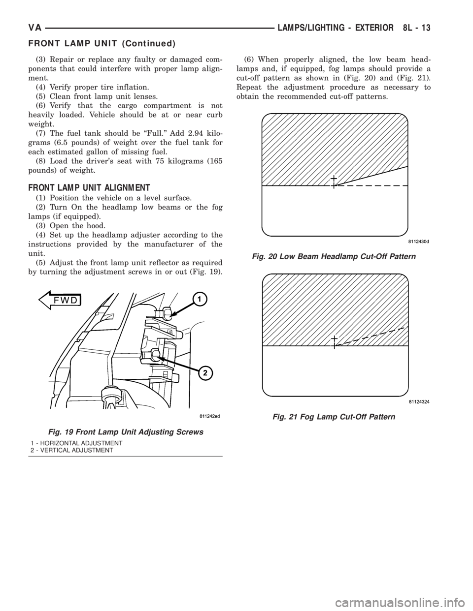
by turning the adjustment screws in or out (Fig. 19).(6) When properly aligned, the low beam head-
lamps and, if equipped, fog lamps should provide a
cut-off pattern as shown in (Fig. 20) and (Fig. 21).
Repeat the adjustment procedure as necessary to
obtain the recommended cut-off patterns.
Fig. 19 Front Lamp Unit Adjusting Screws
1 - HORIZONTAL ADJUSTMENT
2 - VERTICAL ADJUSTMENT
Fig. 20 Low Beam Headlamp Cut-Off Pattern
Fig. 21 Fog Lamp Cut-Off Pattern
VALAMPS/LIGHTING - EXTERIOR 8L - 13
FRONT LAMP UNIT (Continued)