2005 MERCEDES-BENZ SPRINTER checking oil
[x] Cancel search: checking oilPage 14 of 1232
Full synthetic oils, such as Mobilt1 0W-40, is
required if the ASSYST Oil Service Reminder is fol-
lowed. Use of a lower quality oil on this service
schedule may cause severe engine damage.
DESCRIPTION - AUTOMATIC TRANSMISSION
FLUID - NAG1
NOTE: Refer to Service Procedures in this group for
fluid level checking procedures.
Shellt3403 Automatic Transmission Fluid is the
recommended fluid for the NAG1 DaimlerChrysler
automatic transmission.
Dexron II fluid IS NOT recommended. Clutch
chatter can result from the use of improper
fluid.
MopartATF+4, Automatic Transmission Fluid, or
other fluids meeting MS-9602, may be used if Shellt
3403 Automatic Transmission Fluid is not available.
Shellt3403 Automatic Transmission Fluid when
new is red in color. The ATF is dyed red so it can be
identified from other fluids used in the vehicle such
as engine oil or antifreeze. The red color is not per-
manent and is not an indicator of fluid condition. As
the vehicle is driven, the ATF will begin to look
darker in color and may eventually become brown.
This is normal.
FLUID ADDITIVES
DaimlerChrysler strongly recommends against the
addition of any fluids to the transmission, other than
those automatic transmission fluids listed above.
Exceptions to this policy are the use of special dyes
to aid in detecting fluid leaks.
Various ªspecialº additives and supplements exist
that claim to improve shift feel and/or quality. These
additives and others also claim to improve converter
clutch operation and inhibit overheating, oxidation,
varnish, and sludge. These claims have not been sup-
ported to the satisfaction of DaimlerChrysler and
these additivesmust not be used.The use of trans-
mission ªsealersº should also be avoided, since they
may adversely affect the integrity of transmission
seals.
OPERATION - AUTOMATIC TRANSMISSION
FLUID
The automatic transmission fluid is selected based
upon several qualities. The fluid must provide a high
level of protection for the internal components by
providing a lubricating film between adjacent metal
components. The fluid must also be thermally stable
so that it can maintain a consistent viscosity through
a large temperature range. If the viscosity stays con-
stant through the temperature range of operation,transmission operation and shift feel will remain con-
sistent. Transmission fluid must also be a good con-
ductor of heat. The fluid must absorb heat from the
internal transmission components and transfer that
heat to the transmission case.
FLUID CAPACITIES
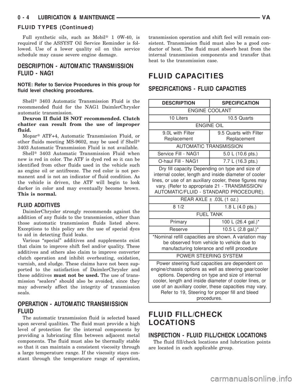
SPECIFICATIONS - FLUID CAPACITIES
DESCRIPTION SPECIFICATION
ENGINE COOLANT
10 Liters 10.5 Quarts
ENGINE OIL
9.0L with Filter
Replacement9.5 Quarts with Filter
Replacement
AUTOMATIC TRANSMISSION
Service Fill - NAG1 5.0 L (10.6 pts.)
O-haul Fill - NAG1 7.7 L (16.3 pts.)
Dry fill capacity Depending on type and size of
internal cooler, length and inside diameter of cooler
lines, or use of an auxiliary cooler, these figures may
vary. (Refer to appropriate 21 - TRANSMISSION/
AUTOMATIC/FLUID - STANDARD PROCEDURE).
REAR AXLE .03L (1 oz.)
8 1/2 1.8 L (4.0 pts.)
FUEL TANK
Primary 100 L (26.4 gal.)*
Reserve 10.5 L (2.8 gal.)*
*Nominal refill capacities are shown. A variation may
be observed from vehicle to vehicle due to
manufacturing tolerance and refill procedure
POWER STEERING SYSTEM
Power steering fluid capacities are dependent on
engine/chassis options as well as steering gear/cooler
options. Depending on type and size of internal
cooler, length and inside diameter of cooler lines, or
use of an auxiliary cooler, these capacities may vary.
Refer to 19, Steering for proper fill and bleed
procedures.
FLUID FILL/CHECK
LOCATIONS
INSPECTION - FLUID FILL/CHECK LOCATIONS
The fluid fill/check locations and lubrication points
are located in each applicable group.
0 - 4 LUBRICATION & MAINTENANCEVA
FLUID TYPES (Continued)
Page 78 of 1232
INSTALLATION
INSTALLATION - FRONT
(1) Install the brake caliper adapter to the steering
knuckle. Tighten to 170 N´m (125 ft. lbs.).
(2) Install the disc brake shoes (Refer to 5 -
BRAKES/HYDRAULIC/MECHANICAL/BRAKE
PADS/SHOES - INSTALLATION).
NOTE: Do not install the brake hose twisted and
ensure freedom of movement.
(3) Install the disc brake caliper. Tighten the bolt
to 14 N´m (124 in. lbs.) (Refer to 5 - BRAKES/HY-
DRAULIC/MECHANICAL/DISC BRAKE CALIPERS
- INSTALLATION).
(4) Install the front wheels (Refer to 22 - TIRES/
WHEELS/WHEELS - INSTALLATION).
(5) Lower the vehicle.
INSTALLATION - REAR
(1) Install the brake caliper adapter to the axle
mount. Tighten to 90 N´m (66 ft. lbs.) for M12X1.5
bolt or 170 N´m (125 ft. lbs.) for M14X1.5 bolt.
(2) Install the disc brake pads (Refer to 5 -
BRAKES/HYDRAULIC/MECHANICAL/BRAKE
PADS/SHOES - INSTALLATION).
NOTE: Do not install the brake hose twisted and
ensure freedom of movement.
(3) Install the disc brake caliper (Refer to 5 -
BRAKES/HYDRAULIC/MECHANICAL/DISC
BRAKE CALIPERS - INSTALLATION).
(4) Install the rear wheels (Refer to 22 - TIRES/
WHEELS/WHEELS - INSTALLATION).
(5) Lower the vehicle.
FLUID
DIAGNOSIS AND TESTING - BRAKE FLUID
CONTAMINATION
Indications of fluid contamination are swollen or
deteriorated rubber parts.
Swollen rubber parts indicate the presence of
petroleum in the brake fluid.
To test for contamination, put a small amount of
drained brake fluid in clear glass jar. If fluid sepa-
rates into layers, there is mineral oil or other fluid
contamination of the brake fluid.
If brake fluid is contaminated, drain and thor-
oughly flush system. Replace master cylinder, ALB
Controller, caliper seals, Antilock Brakes hydraulic
unit and all hydraulic fluid hoses.
STANDARD PROCEDURE - BRAKE FLUID
LEVEL
Always clean the master cylinder reservoir and
caps before checking fluid level. If not cleaned, dirt
could enter the fluid.
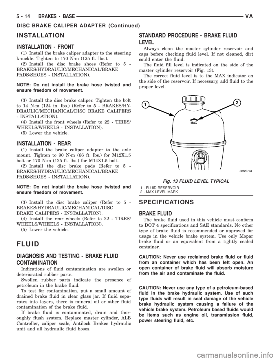
The fluid fill level is indicated on the side of the
master cylinder reservoir (Fig. 13).
The correct fluid level is to the MAX indicator on
the side of the reservoir. If necessary, add fluid to the
proper level.
SPECIFICATIONS
BRAKE FLUID
The brake fluid used in this vehicle must conform
to DOT 4 specifications and SAE standards. No other
type of brake fluid is recommended or approved for
usage in the vehicle brake system. Use only Mopar
brake fluid or an equivalent from a tightly sealed
container.
CAUTION: Never use reclaimed brake fluid or fluid
from an container which has been left open. An
open container of brake fluid will absorb moisture
from the air and contaminate the fluid.
CAUTION: Never use any type of a petroleum-based
fluid in the brake hydraulic system. Use of such
type fluids will result in seal damage of the vehicle
brake hydraulic system causing a failure of the
vehicle brake system. Petroleum based fluids would
be items such as engine oil, transmission fluid,
power steering fluid, etc.
Fig. 13 FLUID LEVEL TYPICAL
1 - FLUID RESERVOIR
2 - MAX LEVEL MARK
5 - 14 BRAKES - BASEVA
DISC BRAKE CALIPER ADAPTER (Continued)
Page 739 of 1232
ENGINE
TABLE OF CONTENTS
page page
ENGINE
DESCRIPTION..........................2
STANDARD PROCEDURE
STANDARD PROCEDURE - COMPRESSION
TESTING ENGINE......................3
STANDARD PROCEDURE - CYLINDER
LEAK DOWN TEST.....................3
STANDARD PROCEDURE - DETERMINING
CYLINDER PRESSURE LOSS.............4
REMOVAL
REMOVAL - ENGINE COVER.............4
REMOVAL............................4
INSTALLATION
INSTALLATION - ENGINE COVER..........7
INSTALLATION........................7
SPECIFICATIONS - TORQUE
SPECIFICATIONS......................8
SPECIAL TOOLS.......................14
AIR CLEANER ELEMENT
REMOVAL.............................20
INSTALLATION.........................20
AIR CLEANER HOUSING
REMOVAL.............................20
INSTALLATION.........................20
CYLINDER HEAD
STANDARD PROCEDURE
STANDARD PROCEDURE - CYLINDER
HEAD BOLT INSPECTION...............21
STANDARD PROCEDURE - MEASURE
CYLINDER HEAD SURFACE.............21
REMOVAL
REMOVAL - CYLINDER HEAD............22
REMOVAL - CYLINDER HEAD FRONT
COVER.............................23
REMOVAL - CYLINDER HEAD GUIDE RAIL . . 24
INSTALLATION
INSTALLATION - CYLINDER HEAD........25
INSTALLATION - CYLINDER HEAD FRONT
COVER.............................26
INSTALLATION - CYLINDER HEAD GUIDE
RAIL...............................26
CAMSHAFT(S)
STANDARD PROCEDURE - CHECKING
CAMSHAFT POSITION.................27
REMOVAL.............................28
INSTALLATION.........................29
CYLINDER HEAD COVER(S)
REMOVAL.............................30
INSTALLATION.........................30VALVE SPRINGS
REMOVAL
REMOVAL - VALVE SPRINGS............31
REMOVAL - VALVES...................31
INSTALLATION
INSTALLATION - VALVE SPRINGS........32
INSTALLATION - VALVES...............33
ENGINE BLOCK
STANDARD PROCEDURE
STANDARD PROCEDURE - REPLACING
ENGINE CORE AND OIL GALLERY PLUGS . . 34
STANDARD PROCEDURE - MEASURING
CYLINDER BORES....................34
CRANKSHAFT
STANDARD PROCEDURE - MEASURE
CRANKSHAFT AND BLOCK JOURNALS....35
REMOVAL.............................35
INSTALLATION.........................36
CRANKSHAFT OIL SEAL - REAR
REMOVAL.............................37
INSTALLATION.........................37
CRANKSHAFT OIL SEAL - FRONT
REMOVAL.............................38
INSTALLATION.........................38
FLYWHEEL
REMOVAL.............................39
INSTALLATION
INSTALLATION.......................39
INSTALLATION.......................39
PISTON & CONNECTING ROD
DESCRIPTION.........................40
STANDARD PROCEDURE
STANDARD PROCEDURE - CHECKING AND
REPAIRING CONNECTING RODS.........40
STANDARD PROCEDURE - MEASURING
PISTON PROTRUSION.................42
REMOVAL.............................42
INSTALLATION.........................43
PISTON RINGS
STANDARD PROCEDURE - PISTON RING
FITTING.............................46
VIBRATION DAMPER
REMOVAL.............................47
INSTALLATION.........................48
VACUUM PUMP
DESCRIPTION.........................48
OPERATION...........................48
REMOVAL.............................48
INSTALLATION.........................49
VAENGINE 9 - 1
Page 778 of 1232
PISTON & CONNECTING ROD
DESCRIPTION
The pistons are of a free floating design. Oil jets in
the engine block lubricate and cool the piston and pin
assembly. The connecting rods have a pressed in
place wrist pin bushing which is lubricated by the oil
jets (Fig. 33).
STANDARD PROCEDURE
STANDARD PROCEDURE - CHECKING AND
REPAIRING CONNECTING RODS
NOTE: Connecting rods with blue discoloration,
cross scores or notches must be replaced. Com-
pensate for different weights by milling off the bal-
ancing weight.
(1) Inspect connecting rod for discoloring, cross
scores and notches.NOTE: Connecting rod and bearing cap are marked
in sets and attached with two sleeves.
(2) Bolt connecting rod bearing cap to connecting
rod. Tighten connecting rod bearing caps to initial
specification (Refer to 9 - ENGINE/ENGINE BLOCK/
PISTON & CONNECTING ROD - INSTALLATION).
NOTE: If the maximum permissible diameter is
exceeded, grind off contact surface of connecting
rod bearing cap by a Maximum of 0.02mm.
(3) Using a dial indicator, measure connecting rod
bearing basic bore, repair as necessary (Fig. 34).
NOTE: If excessive wear is present, press in new
connecting rod bushings.
(4) Measure connecting rod bushing inner diame-
ter (Fig. 34).
(5) Inspect wristpin bushing.
(6) Measure piston pin end play in connecting rod
bushing.
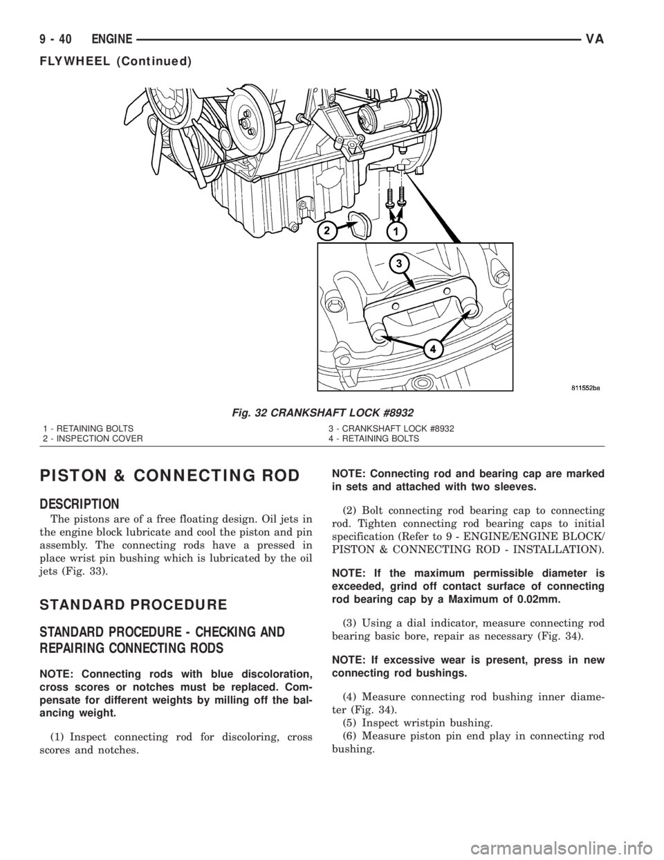
Fig. 32 CRANKSHAFT LOCK #8932
1 - RETAINING BOLTS 3 - CRANKSHAFT LOCK #8932
2 - INSPECTION COVER 4 - RETAINING BOLTS
9 - 40 ENGINEVA
FLYWHEEL (Continued)
Page 873 of 1232
Wipe filler cap clean, then check the fluid level.
The dipstick should indicateCOLDwhen the fluid is
at normal temperature.
(1) Turn steering wheel all the way to the left
(2) Fill the pump fluid reservoir to the proper level
and let the fluid settle for at least two (2) minutes.
(3) Raise the front wheels off the ground.
(4)
Slowly turn the steering wheel lock-to-lock 20
times with the engine off while checking the fluid level.
NOTE: For vehicles with long return lines or oil
coolers turn wheel 40 times.
(5) Start the engine. With the engine idling main-
tain the fluid level.
(6) Lower the front wheels and let the engine idle
for two minutes.
(7) Turn the steering wheel in both direction and
verify power assist and quiet operation of the pump.
If the fluid is extremely foamy or milky looking,
allow the vehicle to stand a few minutes and repeat
the procedure.
CAUTION: Do not run a vehicle with foamy fluid for
an extended period. This may cause pump damage.
STANDARD PROCEDURE - FLUSHING POWER
STEERING SYSTEM
Flushing is required when the power steering/hy-
draulic booster system fluid has become contami-
nated. Contaminated fluid in the steering/booster
system can cause seal deterioration and affect steer-
ing gear/booster spool valve operation.
(1) Raise the front end of the vehicle off the
ground until the wheels are free to turn.
(2) Remove the return line from the pump.
NOTE: If vehicle is equipped with a hydraulic
booster remove both return lines from the pump.
(3) Plug the return line port/ports at the pump.
(4) Position the return line/lines into a large con-
tainer to catch the fluid.
(5) While an assistant is filling the pump reservoir
start the engine.
(6) With the engine running at idle turn the wheel
back and forth.
NOTE: Do not contact or hold the wheel against the
steering stops.
(7) Run a quart of fluid through the system then
stop the engine and install the return line/lines.
(8) Fill the system with fluid and perform Steering
Pump Initial Operation, (Refer to 19 - STEERING/
PUMP - STANDARD PROCEDURE).(9) Start the engine and run it for fifteen minutes
then stop the engine.
(10) Remove the return line/lines from the pump
and plug the pump port/ports.
(11) Pour fresh fluid into the reservoir and check
the draining fluid for contamination. If the fluid is
still contaminated, then flush the system again.
(12) Install the return line/lines and perform
Steering Pump Initial Operation, (Refer to 19 -
STEERING/PUMP - STANDARD PROCEDURE).
REMOVAL
(1) Remove the belt from the power steering pump.
(2) Siphon as much power steering fluid as possi-
ble out of the reservoir.
(3) Remove the high pressure power steering hose
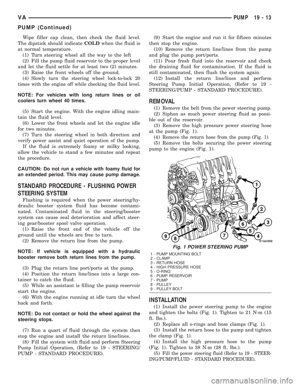
at the pump (Fig. 1).
(4)
Remove the return hose from the pump (Fig. 1).
(5) Remove the bolts securing the power steering
pump to the engine (Fig. 1).
INSTALLATION
(1) Install the power steering pump to the engine
and tighten the bolts (Fig. 1). Tighten to 21 N´m (15
ft. lbs.).
(2) Replace all o-rings and hose clamps (Fig. 1).
(3) Install the return hose to the pump and tighten
the clamp (Fig. 1).
(4) Install the high pressure hose to the pump
(Fig. 1). Tighten to 38 N´m (28 ft. lbs.).
(5)
Fill the power steering fluid (Refer to 19 - STEER-
ING/PUMP/FLUID - STANDARD PROCEDURE).
Fig. 1 POWER STEERING PUMP
1 - PUMP MOUNTING BOLT
2 - CLAMP
3 - RETURN HOSE
4 - HIGH PRESSURE HOSE
5 - O-RING
6 - PUMP RESERVOIR
7 - PUMP
8 - PULLEY
9 - PULLEY BOLT
VAPUMP 19 - 13
PUMP (Continued)
Page 899 of 1232
DIAGNOSIS AND TESTING
DIAGNOSIS AND TESTING - AUTOMATIC
TRANSMISSION
CAUTION: Before attempting any repair on a NAG1
automatic transmission, check for Diagnostic Trou-
ble Codes with the DRBTscan tool.
Transmission malfunctions may be caused by these
general conditions:
²Poor engine performance.
²Improper adjustments.
²Hydraulic malfunctions.
²Mechanical malfunctions.
²Electronic malfunctions.
²Transfer case performance.
Diagnosis of these problems should always begin
by checking the easily accessible variables: fluid level
and condition, gearshift cable adjustment. Then per-
form a road test to determine if the problem has been
corrected or if more diagnosis is necessary.
DIAGNOSIS AND TESTING - PRELIMINARY
Two basic procedures are required. One procedure
for vehicles that are drivable and an alternate proce-
dure for disabled vehicles (will not back up or move
forward).
VEHICLE IS DRIVABLE
(1) Check for transmission fault codes using DRBt
scan tool.
(2) Check fluid level and condition.
(3) Adjust gearshift cable if complaint was based
on delayed, erratic, or harsh shifts.
(4) Road test and note how transmission upshifts,
downshifts, and engages.
VEHICLE IS DISABLED
(1) Check fluid level and condition.(2) Check for broken or disconnected gearshift
cable.
(3) Check for cracked, leaking cooler lines, or loose
or missing pressure-port plugs.
(4) Raise and support vehicle on safety stands,
start engine, shift transmission into gear, and note
following:
(a) If propeller shaft turns but wheels do not,
problem is with differential or axle shafts.
(b) If propeller shaft does not turn and transmis-
sion is noisy, stop engine. Remove oil pan, and
check for debris. If pan is clear, remove transmis-
sion and check for damaged driveplate, converter,
oil pump, or input shaft.
(c) If propeller shaft does not turn and transmis-
sion is not noisy, perform hydraulic-pressure test to
determine if problem is hydraulic or mechanical.
DIAGNOSIS AND TESTING - ROAD TESTING
Before road testing, be sure the fluid level and con-
trol cable adjustments have been checked and
adjusted if necessary. Verify that all diagnostic trou-
ble codes have been resolved.
Observe engine performance during the road test.
A poorly tuned engine will not allow accurate analy-
sis of transmission operation.
Operate the transmission in all gear ranges. Check
for shift variations and engine flare which indicates
slippage. Note if shifts are harsh, spongy, delayed,
early, or if part throttle downshifts are sensitive.
Slippage indicated by engine flare, usually means
clutch, overrunning clutch, or line pressure problems.
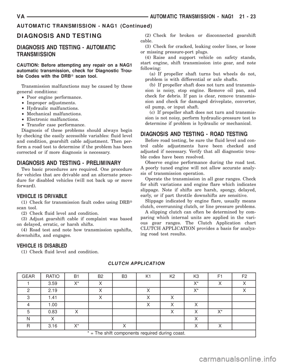
A slipping clutch can often be determined by com-
paring which internal units are applied in the vari-
ous gear ranges. The Clutch Application chart
CLUTCH APPLICATION provides a basis for analyz-
ing road test results.
CLUTCH APPLICATION
GEAR RATIO B1 B2 B3 K1 K2 K3 F1 F2
1 3.59 X* X X* X X
2 2.19 X X X* X
3 1.41 X X X
4 1.00 X X X
5 0.83 X X X X*
NX X
R 3.16 X* X X X
* = The shift components required during coast.
VAAUTOMATIC TRANSMISSION - NAG1 21 - 23
AUTOMATIC TRANSMISSION - NAG1 (Continued)
Page 906 of 1232
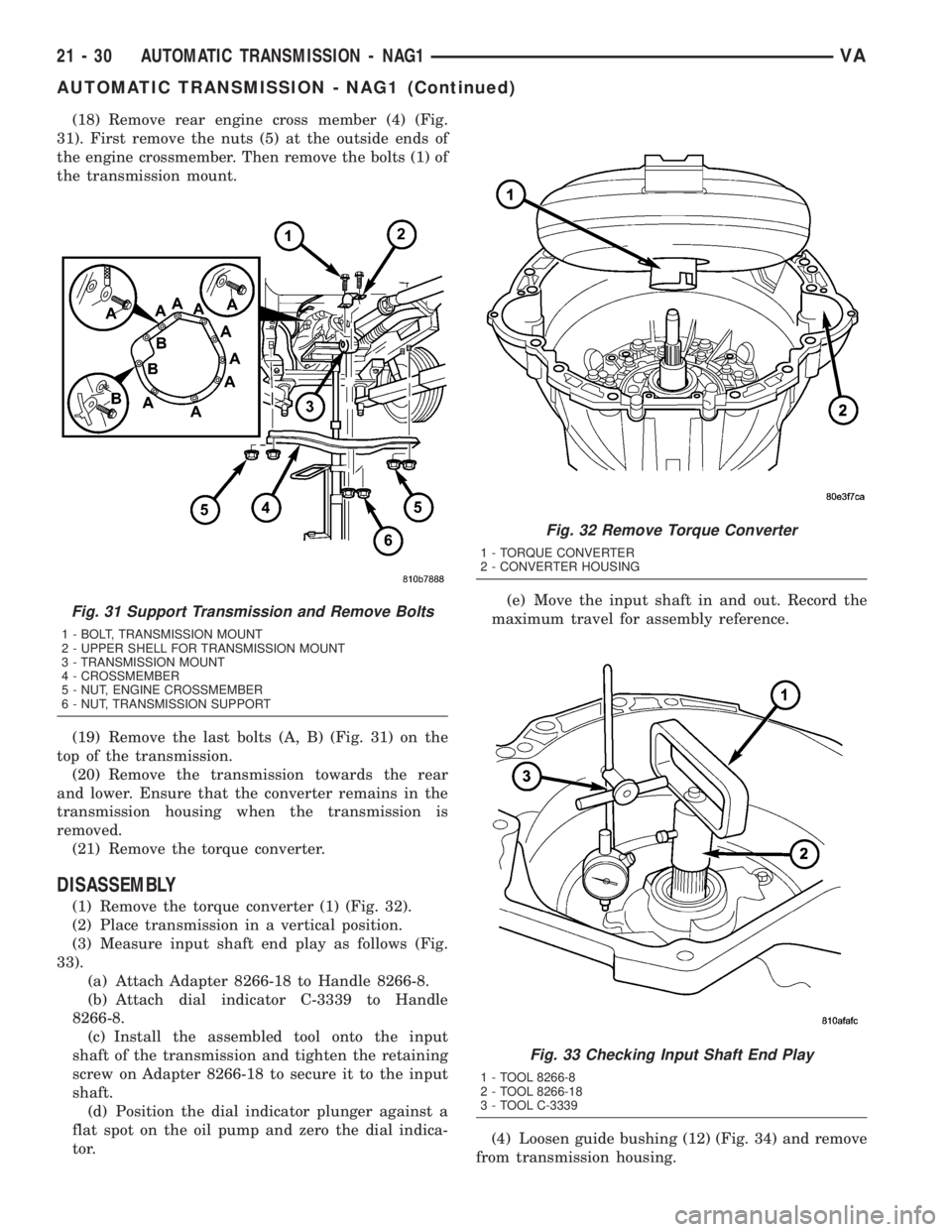
(18) Remove rear engine cross member (4) (Fig.
31). First remove the nuts (5) at the outside ends of
the engine crossmember. Then remove the bolts (1) of
the transmission mount.
(19) Remove the last bolts (A, B) (Fig. 31) on the
top of the transmission.
(20) Remove the transmission towards the rear
and lower. Ensure that the converter remains in the
transmission housing when the transmission is
removed.
(21) Remove the torque converter.
DISASSEMBLY
(1) Remove the torque converter (1) (Fig. 32).
(2) Place transmission in a vertical position.
(3) Measure input shaft end play as follows (Fig.
33).
(a) Attach Adapter 8266-18 to Handle 8266-8.
(b) Attach dial indicator C-3339 to Handle
8266-8.
(c) Install the assembled tool onto the input
shaft of the transmission and tighten the retaining
screw on Adapter 8266-18 to secure it to the input
shaft.
(d) Position the dial indicator plunger against a
flat spot on the oil pump and zero the dial indica-
tor.(e) Move the input shaft in and out. Record the
maximum travel for assembly reference.
(4) Loosen guide bushing (12) (Fig. 34) and remove
from transmission housing.
Fig. 31 Support Transmission and Remove Bolts
1 - BOLT, TRANSMISSION MOUNT
2 - UPPER SHELL FOR TRANSMISSION MOUNT
3 - TRANSMISSION MOUNT
4 - CROSSMEMBER
5 - NUT, ENGINE CROSSMEMBER
6 - NUT, TRANSMISSION SUPPORT
Fig. 32 Remove Torque Converter
1 - TORQUE CONVERTER
2 - CONVERTER HOUSING
Fig. 33 Checking Input Shaft End Play
1 - TOOL 8266-8
2 - TOOL 8266-18
3 - TOOL C-3339
21 - 30 AUTOMATIC TRANSMISSION - NAG1VA
AUTOMATIC TRANSMISSION - NAG1 (Continued)
Page 978 of 1232
DIAGNOSIS AND TESTING
DIAGNOSIS AND TESTING - EFFECTS OF
INCORRECT FLUID LEVEL
A low fluid level allows the pump to take in air
along with the fluid. Air in the fluid will cause fluid
pressures to be low and develop slower than normal.
If the transmission is overfilled, the gears churn the
fluid into foam. This aerates the fluid and causing
the same conditions occurring with a low level. In
either case, air bubbles cause fluid overheating, oxi-
dation and varnish buildup which interferes with
valve and clutch operation. Foaming also causes fluid
expansion which can result in fluid overflow from the
transmission vent or fill tube. Fluid overflow can eas-
ily be mistaken for a leak if inspection is not careful.
DIAGNOSIS AND TESTING - CAUSES OF
BURNT FLUID
Burnt, discolored fluid is a result of overheating
which has three primary causes.
(1) Internal clutch slippage, usually caused by low
line pressure, inadequate clutch apply pressure, or
clutch seal failure.
(2) A result of restricted fluid flow through the
main and/or auxiliary cooler. This condition is usu-
ally the result of a faulty or improperly installed
drainback valve, a damaged main cooler, or severe
restrictions in the coolers and lines caused by debris
or kinked lines.
(3) Heavy duty operation with a vehicle not prop-
erly equipped for this type of operation. Trailer tow-
ing or similar high load operation will overheat the
transmission fluid if the vehicle is improperly
equipped. Such vehicles should have an auxiliary
transmission fluid cooler, a heavy duty cooling sys-
tem, and the engine/axle ratio combination needed to
handle heavy loads.
DIAGNOSIS AND TESTING - FLUID
CONTAMINATION
Transmission fluid contamination is generally a
result of:
²adding incorrect fluid
²failure to clean dipstick and fill tube when
checking level
²engine coolant entering the fluid
²internal failure that generates debris
²overheat that generates sludge (fluid break-
down)
²failure to replace contaminated converter after
repair
The use of non-recommended fluids can result in
transmission failure. The usual results are erratic
shifts, slippage, abnormal wear and eventual failuredue to fluid breakdown and sludge formation. Avoid
this condition by using recommended fluids only.
The dipstick cap and fill tube should be wiped
clean before checking fluid level. Dirt, grease and
other foreign material on the cap and tube could fall
into the tube if not removed beforehand. Take the
time to wipe the cap and tube clean before withdraw-
ing the dipstick.
Engine coolant in the transmission fluid is gener-
ally caused by a cooler malfunction. The only remedy
is to replace the radiator as the cooler in the radiator
is not a serviceable part. If coolant has circulated
through the transmission, an overhaul is necessary.
The torque converter should be replaced whenever
a failure generates sludge and debris. This is neces-
sary because normal converter flushing procedures
will not remove all contaminants.
STANDARD PROCEDURE
STANDARD PROCEDURE - CHECK OIL LEVEL
(1) Verify that the vehicle is parked on a level sur-
face.
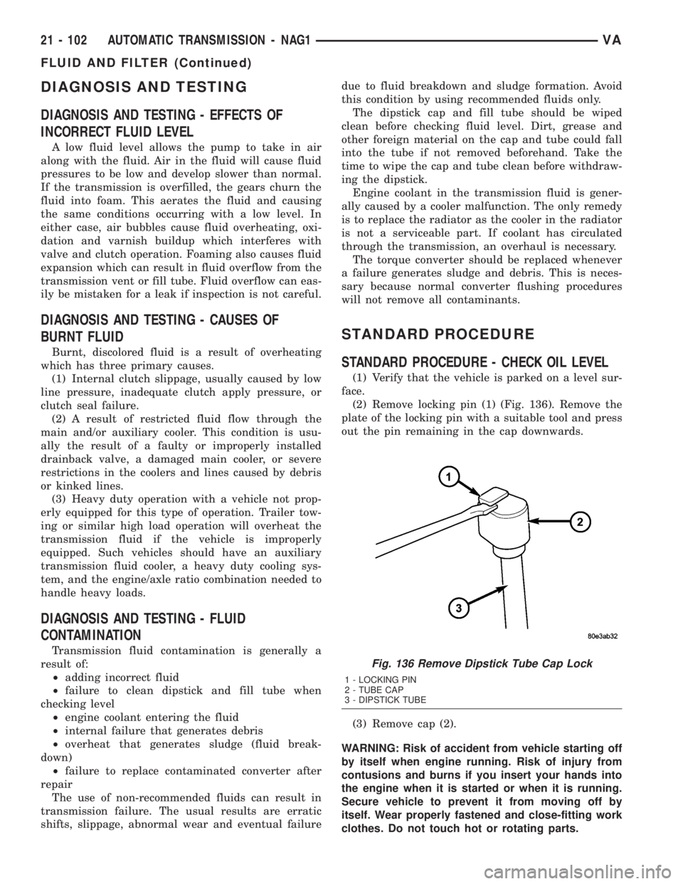
(2) Remove locking pin (1) (Fig. 136). Remove the
plate of the locking pin with a suitable tool and press
out the pin remaining in the cap downwards.
(3) Remove cap (2).
WARNING: Risk of accident from vehicle starting off
by itself when engine running. Risk of injury from
contusions and burns if you insert your hands into
the engine when it is started or when it is running.
Secure vehicle to prevent it from moving off by
itself. Wear properly fastened and close-fitting work
clothes. Do not touch hot or rotating parts.
Fig. 136 Remove Dipstick Tube Cap Lock
1 - LOCKING PIN
2 - TUBE CAP
3 - DIPSTICK TUBE
21 - 102 AUTOMATIC TRANSMISSION - NAG1VA
FLUID AND FILTER (Continued)