2005 MERCEDES-BENZ SPRINTER ground clearance
[x] Cancel search: ground clearancePage 17 of 1232
If the Engine is Damaged
For towing distances up to 30 miles (about 50
km)
²Shift selector lever in ªNº position.
²Do not exceed a towing speed of 30 m.p.h. (50
km/h).
For towing distances greater than 30 mile
(about 50 km)
²Remove the propeller shafts leading to the drive
axles. The vehicle can be towed without restriction.
If the Transmission is Damaged
²Remove the propeller shafts leading to the drive
axles. The vehicle can be towed without restriction.
If the Front Axle is Damaged
²Raise the front axle.
²Observe the same towing restrictions as for
engine damage.
If the Rear Axle is Damaged
²Raise the rear axle.
NOTE: Comply with local legal regulations regard-
ing towing vehicles.
SAFETY PRECAUTIONS
NOTE: The following safety precautions must be
observed when towing a vehicle.
²Secure loose and protruding parts.
²Always use a safety chain system that is inde-
pendent of the lifting and towing equipment.
²Do not allow towing equipment to contact the
disabled vehicle's fuel tank.
²Do not allow anyone under the disabled vehicle
while it is lifted by the towing device.
²Do not allow passengers to ride in a vehicle
being towed.
²Always observe state and local laws regarding
towing regulations.
²Do not tow a vehicle in a manner that could
jeopardize the safety of the operator, pedestrians or
other motorists.
²Do not attach tow chains, T-hooks, J-hooks, or a
tow sling to a bumper, steering linkage, drive shafts
or a non-reinforced frame hole.
²Remove exhaust pipe tips that interfere with the
tow sling and crossbar
²Padding should be placed between the tow sling/
crossbar and any painted surfaces
²When placing tow hooks on the rear axle, posi-
tion them so they do not damage the brake tubing or
hoses²Do not tow the vehicle by connecting to the front
or rear shock absorbers
²Do not tow a heavily loaded vehicle. Damage to
the vehicle may result. Use a flatbed device to trans-
port a loaded vehicle.
GROUND CLEARANCE
CAUTION: If vehicle is towed with wheels removed,
install lug nuts to retain brake drums.
A towed vehicle should be raised until lifted wheels
are a minimum 100 mm (4 in) from the ground. Be
sure there is adequate ground clearance at the oppo-
site end of the vehicle, especially when towing over
rough terrain, steep rises in the road or if the vehicle
is equipped with air dams, spoilers, and/or ground
effect panels. If necessary, remove the wheels from
the lifted end of the vehicle and lower the vehicle
closer to the ground, to increase the ground clearance
at the opposite end of the vehicle. Install lug nuts on
wheel attaching studs to retain brake drums.
RAMP ANGLE
If a vehicle with flat-bed towing equipment is used,
the approach ramp angle should not exceed 15
degrees.
TOWING WHEN KEYS ARE NOT AVAILABLE
When the vehicle is locked and keys are not avail-
able, use a flat bed hauler. A Wheel-lift or Sling-type
device can be used provided all the wheels are lifted
off the ground using tow dollies.
MAINTENANCE SCHEDULES
DESCRIPTION
The use of Special lubricant additives is not recom-
mended. The use of such additives may affect the
warranty rights. With regard to legal stipulations
concerning emissions control, please note that
engines have to be serviced and adjusted in accor-
dance with special instructions and using special
measuring equipment. Modifications to or interfer-
ence with the emissions control systems are not per-
missible.
MAINTENANCE - WITHOUT ASSYST
MAINTENANCE COMPUTER
Maintenance Intervals
²Oil service ±Normal Operationevery 10,000
miles or 16,000 km or 12 months.
²Maintenance service every 20,000 miles or
32,000 km.
Additional work must be carried out at yearly
intervals.
VALUBRICATION & MAINTENANCE 0 - 7
TOWING (Continued)
Page 202 of 1232
FRONT FOG LAMPS
Vehicles equipped with optional front fog lamps
have a front fog lamp relay installed in a relay
bracket located below the forward edge of the driver
side front seat cushion within the driver side front
seat riser, a fog lamp switch installed in the cluster
bezel on the instrument panel outboard of the steer-
ing column, and a fog lamp bulb installed in each of
the two front lamp units. The front fog lamps have a
path to ground at all times through their connection
to the vehicle wire harness. The headlamp switch cir-
cuitry of the left (lighting) control stalk of the multi-
function switch controls front fog lamp operation by
providing battery current to the front fog lamp relay
only when the low beam headlamps are selected. The
fog lamp switch controls front fog lamp operation by
energizing or de-energizing the front fog lamp relay
control coil.
HAZARD WARNING LAMPS
With the hazard switch in the On position, the
hazard switch button illuminates and the right and
left turn signal indicators as well as the right and
left turn signal lamps begin to flash on and off. When
the hazard warning system is activated, the hazard
switch circuitry within the multi-function switch and
the wipers, turn signals and engine start control
module electronic circuitry within the fuse block will
repeatedly energize and de-energize the turn signal
relay located in the fuse block. The turn signal relay
switches battery current from a fused B(+) fuse in
the fuse block to the turn signal indicators and the
turn signal lamps. The flashing of the hazard switch
button illumination lamp is also controlled by the
output from the turn signal relay.
HEADLAMPS
The headlamp system includes the exterior lighting
switches integral to the left (lighting) control stalk of
the multi-function switch as well as the low and high
beam bulbs installed in the right and left front lamp
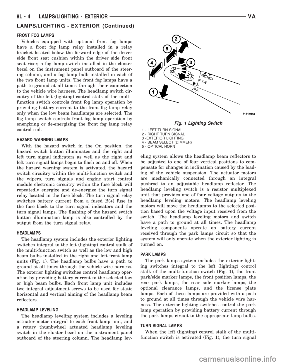
units (Fig. 1). The headlamp bulbs have a path to
ground at all times through the vehicle wire harness.
The exterior lighting switches control headlamp oper-
ation by providing battery current to the selected low
or high beam bulbs. Each front lamp unit includes
two integral adjustment screws to be used for static
horizontal and vertical aiming of the headlamp beam
reflectors.
HEADLAMP LEVELING
The headlamp leveling system includes a leveling
actuator motor integral to each front lamp unit, and
a rotary thumbwheel actuated headlamp leveling
switch in the cluster bezel on the instrument panel
outboard of the steering column. The headlamp lev-eling system allows the headlamp beam reflectors to
be adjusted to one of four vertical positions to com-
pensate for changes in inclination caused by the load-
ing of the vehicle suspension. The actuator motors
are mechanically connected through an integral
pushrod to an adjustable headlamp reflector. The
headlamp leveling switch is a resistor multiplexed
unit that provides one of four voltage outputs to the
headlamp leveling motors. The headlamp leveling
motors will move the headlamps to the selected posi-
tion based upon the voltage input received from the
switch. The headlamp leveling motors and switch
have a path to ground at all times. The headlamp
leveling components operate on battery current
received through the park lamps circuit so that the
system will only operate when the exterior lighting is
turned on.
PARK LAMPS
The park lamps system includes the exterior light-
ing switches integral to the left (lighting) control
stalk of the multi-function switch (Fig. 1), the front
park/side marker lamps, the front position lamps, the
rear park lamps, the rear side marker lamps, the
optional clearance lamps, and the license plate
lamps. Each of these lamps are provided with a path
to ground at all times through the vehicle wire har-
ness. The exterior lighting switches control the park
lamp operation by providing battery current through
the park lamps circuit to the appropriate lamp bulbs.
TURN SIGNAL LAMPS
When the left (lighting) control stalk of the multi-
function switch is activated (Fig. 1), the turn signal
Fig. 1 Lighting Switch
1 - LEFT TURN SIGNAL
2 - RIGHT TURN SIGNAL
3 -EXTERIOR LIGHTING
4 - BEAM SELECT (DIMMER)
5 - OPTICAL HORN
8L - 4 LAMPS/LIGHTING - EXTERIORVA
LAMPS/LIGHTING - EXTERIOR (Continued)
Page 207 of 1232
INSTALLATION
(1) Position the clearance lamp unit close enough
to the vehicle to reconnect the vehicle wire harness
to the bulb holder connector receptacle (Fig. 11).
(2) Position the clearance lamp unit to the vehicle.
(3) Install and tighten the two screws that secure
the clearance lamp unit to the vehicle.
(4) Reconnect the battery negative cable.
DAYTIME RUNNING LAMP
RELAY
REMOVAL
Daytime Running Lamps (DRL) are only used in
vehicles manufactured for the Canadian market,
where this is required equipment. On vehicles
equipped with DRL, a right and a left DRL relay are
each located in a dedicated connector of the vehicle
wire harness. Each connector is snapped into an
opening in a stamped sheet metal bracket which is
secured with screws within the driver side front seat
riser just beneath the seat riser cover panel.
WARNING: ON VEHICLES EQUIPPED WITH AIRBAGS,
DISABLE THE SUPPLEMENTAL RESTRAINT SYSTEM
BEFORE ATTEMPTING ANY STEERING WHEEL,
STEERING COLUMN, DRIVER AIRBAG, PASSENGER
AIRBAG, SEAT BELT TENSIONER, OR INSTRUMENT
PANEL COMPONENT DIAGNOSIS OR SERVICE. DIS-
CONNECT AND ISOLATE THE BATTERY NEGATIVE
(GROUND) CABLE, THEN WAIT TWO MINUTES FOR
THE SYSTEM CAPACITOR TO DISCHARGE BEFORE
PERFORMING FURTHER DIAGNOSIS OR SERVICE.
THIS IS THE ONLY SURE WAY TO DISABLE THE SUP-
PLEMENTAL RESTRAINT SYSTEM. FAILURE TO TAKE
THE PROPER PRECAUTIONS COULD RESULT IN
ACCIDENTAL AIRBAG DEPLOYMENT AND POSSIBLE
PERSONAL INJURY.
(1) Disconnect and isolate the battery negative
cable.
(2) Move the driver side front seat to its most for-
ward position for easiest access to the seat riser
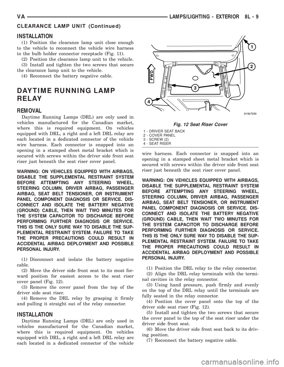
cover panel (Fig. 12).
(3) Remove the cover panel from the top of the
driver side seat riser.
(4) Remove the DRL relay by grasping it firmly
and pulling it straight out of the relay connector.
INSTALLATION
Daytime Running Lamps (DRL) are only used in
vehicles manufactured for the Canadian market,
where this is required equipment. On vehicles
equipped with DRL, a right and a left DRL relay are
each located in a dedicated connector of the vehiclewire harness. Each connector is snapped into an
opening in a stamped sheet metal bracket which is
secured with screws within the driver side front seat
riser just beneath the seat riser cover panel.
WARNING: ON VEHICLES EQUIPPED WITH AIRBAGS,
DISABLE THE SUPPLEMENTAL RESTRAINT SYSTEM
BEFORE ATTEMPTING ANY STEERING WHEEL,
STEERING COLUMN, DRIVER AIRBAG, PASSENGER
AIRBAG, SEAT BELT TENSIONER, OR INSTRUMENT
PANEL COMPONENT DIAGNOSIS OR SERVICE. DIS-
CONNECT AND ISOLATE THE BATTERY NEGATIVE
(GROUND) CABLE, THEN WAIT TWO MINUTES FOR
THE SYSTEM CAPACITOR TO DISCHARGE BEFORE
PERFORMING FURTHER DIAGNOSIS OR SERVICE.
THIS IS THE ONLY SURE WAY TO DISABLE THE SUP-
PLEMENTAL RESTRAINT SYSTEM. FAILURE TO TAKE
THE PROPER PRECAUTIONS COULD RESULT IN
ACCIDENTAL AIRBAG DEPLOYMENT AND POSSIBLE
PERSONAL INJURY.
(1) Position the DRL relay to the relay connector.
(2) Align the DRL relay terminals with the termi-
nal cavities in the relay connector.
(3) Using hand pressure, push firmly and evenly
on the top of the DRL relay until the terminals are
fully seated in the relay connector.
(4) Position the cover panel onto the top of the
driver side seat riser (Fig. 12).
(5) Install and tighten the two screws that secure
the cover panel to the top of the seat riser under the
driver side front seat.
(6) Move the driver side front seat back to its driv-
ing position.
(7) Reconnect the battery negative cable.
Fig. 12 Seat Riser Cover
1 - DRIVER SEAT BACK
2 - COVER PANEL
3 - SCREW (2)
4 - SEAT RISER
VALAMPS/LIGHTING - EXTERIOR 8L - 9
CLEARANCE LAMP UNIT (Continued)
Page 250 of 1232
(1) Reconnect and latch the vehicle wire harness
connector for the ACM to the ACM connector recep-
tacle located on the left facing side of the module
(Fig. 12).
(2) Carefully position the ACM cover base plate
onto the mounting bracket that is welded onto the
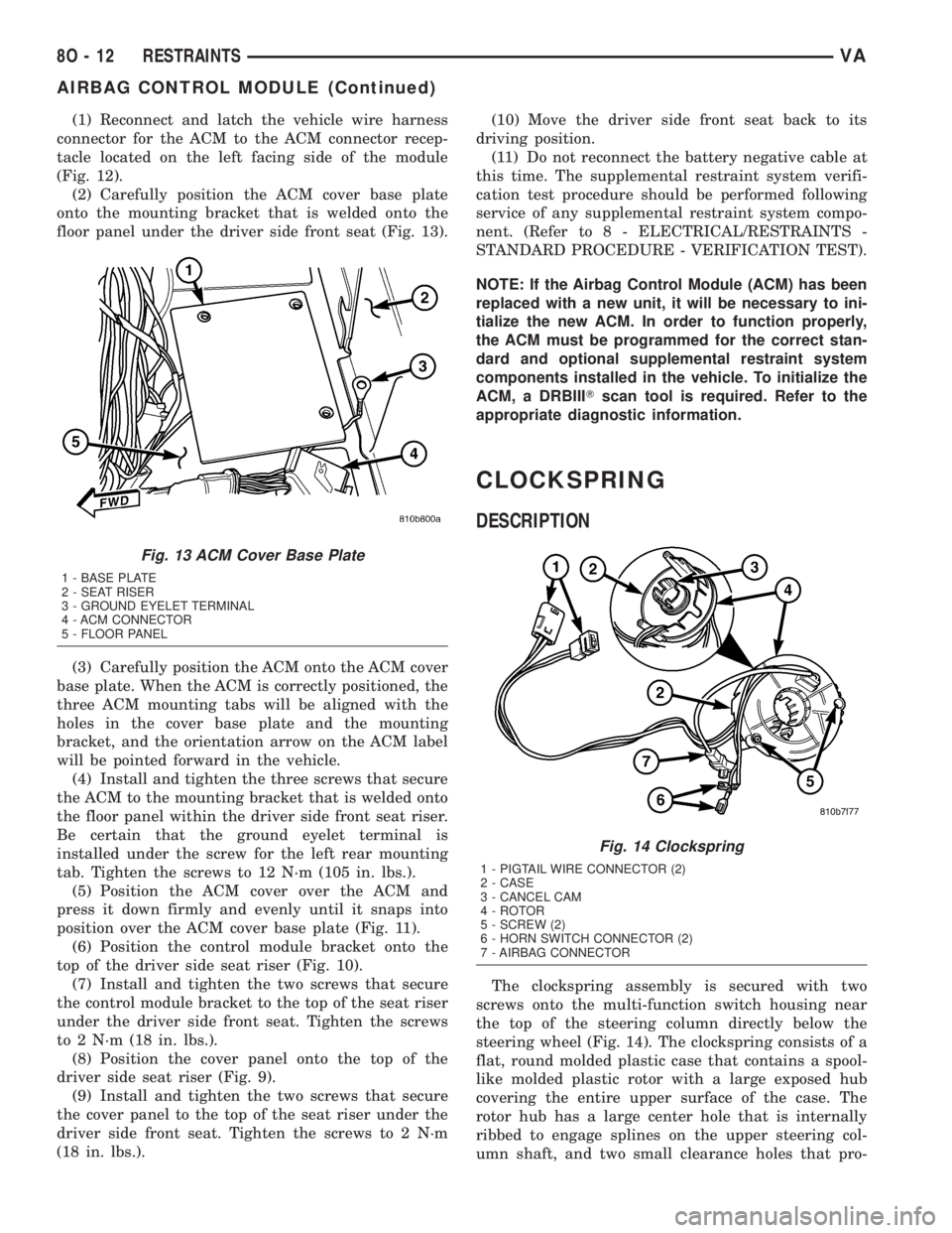
floor panel under the driver side front seat (Fig. 13).
(3) Carefully position the ACM onto the ACM cover
base plate. When the ACM is correctly positioned, the
three ACM mounting tabs will be aligned with the
holes in the cover base plate and the mounting
bracket, and the orientation arrow on the ACM label
will be pointed forward in the vehicle.
(4) Install and tighten the three screws that secure
the ACM to the mounting bracket that is welded onto
the floor panel within the driver side front seat riser.
Be certain that the ground eyelet terminal is
installed under the screw for the left rear mounting
tab. Tighten the screws to 12 N´m (105 in. lbs.).
(5) Position the ACM cover over the ACM and
press it down firmly and evenly until it snaps into
position over the ACM cover base plate (Fig. 11).
(6) Position the control module bracket onto the
top of the driver side seat riser (Fig. 10).
(7) Install and tighten the two screws that secure
the control module bracket to the top of the seat riser
under the driver side front seat. Tighten the screws
to 2 N´m (18 in. lbs.).
(8) Position the cover panel onto the top of the
driver side seat riser (Fig. 9).
(9) Install and tighten the two screws that secure
the cover panel to the top of the seat riser under the
driver side front seat. Tighten the screws to 2 N´m
(18 in. lbs.).(10) Move the driver side front seat back to its
driving position.
(11) Do not reconnect the battery negative cable at
this time. The supplemental restraint system verifi-
cation test procedure should be performed following
service of any supplemental restraint system compo-
nent. (Refer to 8 - ELECTRICAL/RESTRAINTS -
STANDARD PROCEDURE - VERIFICATION TEST).
NOTE: If the Airbag Control Module (ACM) has been
replaced with a new unit, it will be necessary to ini-
tialize the new ACM. In order to function properly,
the ACM must be programmed for the correct stan-
dard and optional supplemental restraint system
components installed in the vehicle. To initialize the
ACM, a DRBIIITscan tool is required. Refer to the
appropriate diagnostic information.
CLOCKSPRING
DESCRIPTION
The clockspring assembly is secured with two
screws onto the multi-function switch housing near
the top of the steering column directly below the
steering wheel (Fig. 14). The clockspring consists of a
flat, round molded plastic case that contains a spool-
like molded plastic rotor with a large exposed hub
covering the entire upper surface of the case. The
rotor hub has a large center hole that is internally
ribbed to engage splines on the upper steering col-
umn shaft, and two small clearance holes that pro-
Fig. 13 ACM Cover Base Plate
1 - BASE PLATE
2 - SEAT RISER
3 - GROUND EYELET TERMINAL
4 - ACM CONNECTOR
5 - FLOOR PANEL
Fig. 14 Clockspring
1 - PIGTAIL WIRE CONNECTOR (2)
2 - CASE
3 - CANCEL CAM
4 - ROTOR
5 - SCREW (2)
6 - HORN SWITCH CONNECTOR (2)
7 - AIRBAG CONNECTOR
8O - 12 RESTRAINTSVA
AIRBAG CONTROL MODULE (Continued)
Page 252 of 1232
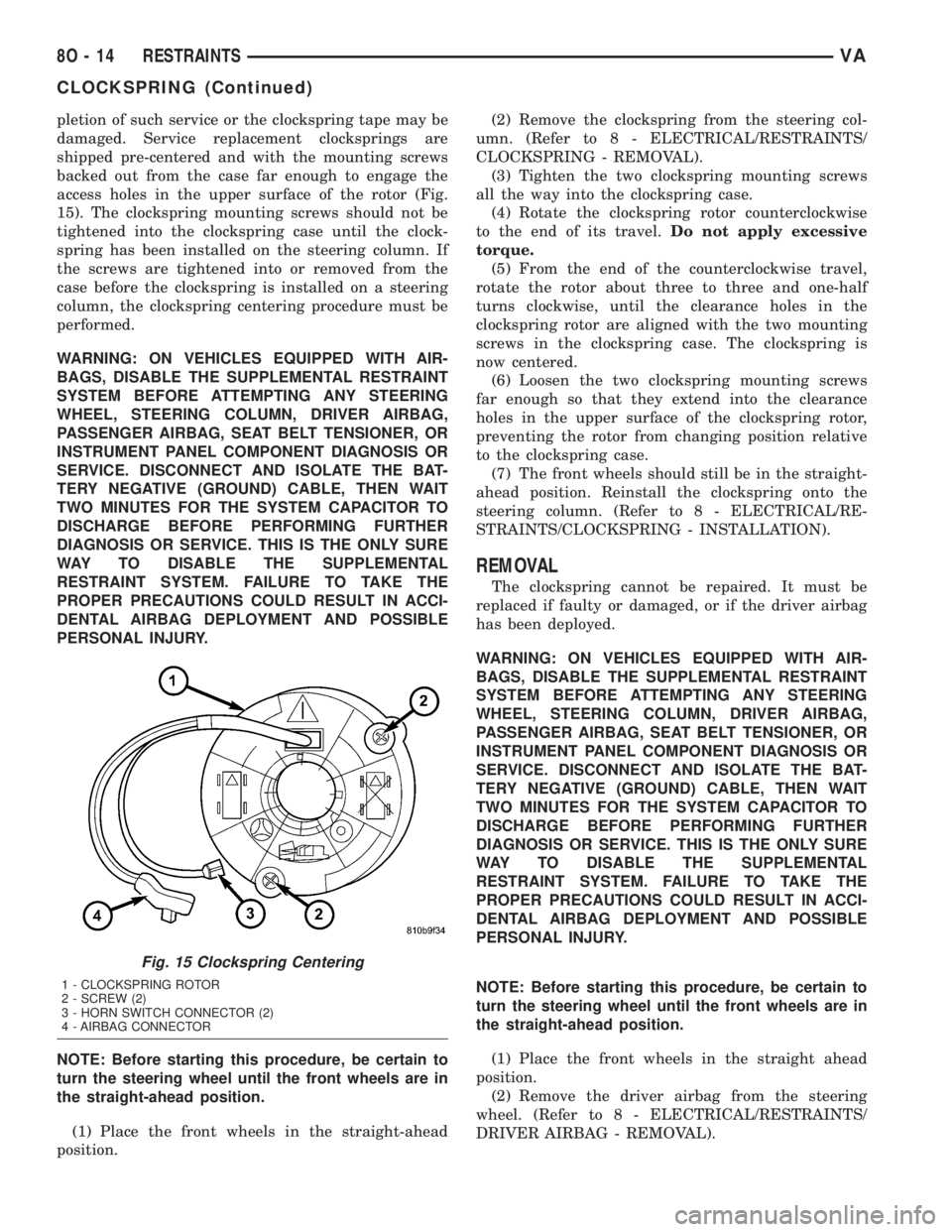
pletion of such service or the clockspring tape may be
damaged. Service replacement clocksprings are
shipped pre-centered and with the mounting screws
backed out from the case far enough to engage the
access holes in the upper surface of the rotor (Fig.
15). The clockspring mounting screws should not be
tightened into the clockspring case until the clock-
spring has been installed on the steering column. If
the screws are tightened into or removed from the
case before the clockspring is installed on a steering
column, the clockspring centering procedure must be
performed.
WARNING: ON VEHICLES EQUIPPED WITH AIR-
BAGS, DISABLE THE SUPPLEMENTAL RESTRAINT
SYSTEM BEFORE ATTEMPTING ANY STEERING
WHEEL, STEERING COLUMN, DRIVER AIRBAG,
PASSENGER AIRBAG, SEAT BELT TENSIONER, OR
INSTRUMENT PANEL COMPONENT DIAGNOSIS OR
SERVICE. DISCONNECT AND ISOLATE THE BAT-
TERY NEGATIVE (GROUND) CABLE, THEN WAIT
TWO MINUTES FOR THE SYSTEM CAPACITOR TO
DISCHARGE BEFORE PERFORMING FURTHER
DIAGNOSIS OR SERVICE. THIS IS THE ONLY SURE
WAY TO DISABLE THE SUPPLEMENTAL
RESTRAINT SYSTEM. FAILURE TO TAKE THE
PROPER PRECAUTIONS COULD RESULT IN ACCI-
DENTAL AIRBAG DEPLOYMENT AND POSSIBLE
PERSONAL INJURY.
NOTE: Before starting this procedure, be certain to
turn the steering wheel until the front wheels are in
the straight-ahead position.
(1) Place the front wheels in the straight-ahead
position.(2) Remove the clockspring from the steering col-
umn. (Refer to 8 - ELECTRICAL/RESTRAINTS/
CLOCKSPRING - REMOVAL).
(3) Tighten the two clockspring mounting screws
all the way into the clockspring case.
(4) Rotate the clockspring rotor counterclockwise
to the end of its travel.Do not apply excessive
torque.
(5) From the end of the counterclockwise travel,
rotate the rotor about three to three and one-half
turns clockwise, until the clearance holes in the
clockspring rotor are aligned with the two mounting
screws in the clockspring case. The clockspring is
now centered.
(6) Loosen the two clockspring mounting screws
far enough so that they extend into the clearance
holes in the upper surface of the clockspring rotor,
preventing the rotor from changing position relative
to the clockspring case.
(7) The front wheels should still be in the straight-
ahead position. Reinstall the clockspring onto the
steering column. (Refer to 8 - ELECTRICAL/RE-
STRAINTS/CLOCKSPRING - INSTALLATION).
REMOVAL
The clockspring cannot be repaired. It must be
replaced if faulty or damaged, or if the driver airbag
has been deployed.
WARNING: ON VEHICLES EQUIPPED WITH AIR-
BAGS, DISABLE THE SUPPLEMENTAL RESTRAINT
SYSTEM BEFORE ATTEMPTING ANY STEERING
WHEEL, STEERING COLUMN, DRIVER AIRBAG,
PASSENGER AIRBAG, SEAT BELT TENSIONER, OR
INSTRUMENT PANEL COMPONENT DIAGNOSIS OR
SERVICE. DISCONNECT AND ISOLATE THE BAT-
TERY NEGATIVE (GROUND) CABLE, THEN WAIT
TWO MINUTES FOR THE SYSTEM CAPACITOR TO
DISCHARGE BEFORE PERFORMING FURTHER
DIAGNOSIS OR SERVICE. THIS IS THE ONLY SURE
WAY TO DISABLE THE SUPPLEMENTAL
RESTRAINT SYSTEM. FAILURE TO TAKE THE
PROPER PRECAUTIONS COULD RESULT IN ACCI-
DENTAL AIRBAG DEPLOYMENT AND POSSIBLE
PERSONAL INJURY.
NOTE: Before starting this procedure, be certain to
turn the steering wheel until the front wheels are in
the straight-ahead position.
(1) Place the front wheels in the straight ahead
position.
(2) Remove the driver airbag from the steering
wheel. (Refer to 8 - ELECTRICAL/RESTRAINTS/
DRIVER AIRBAG - REMOVAL).
Fig. 15 Clockspring Centering
1 - CLOCKSPRING ROTOR
2 - SCREW (2)
3 - HORN SWITCH CONNECTOR (2)
4 - AIRBAG CONNECTOR
8O - 14 RESTRAINTSVA
CLOCKSPRING (Continued)
Page 253 of 1232
(3) Disconnect the clockspring upper pigtail wire
connectors from the terminals of the horn switch
located in the hub cavity of the steering wheel.
(4) Remove the steering wheel from the steering
column. (Refer to 19 - STEERING/COLUMN/STEER-
ING WHEEL - REMOVAL).
(5) Remove the steering column opening cover
from the instrument panel. (Refer to 23 - BODY/IN-
STRUMENT PANEL/STEERING COLUMN OPEN-
ING COVER - REMOVAL).
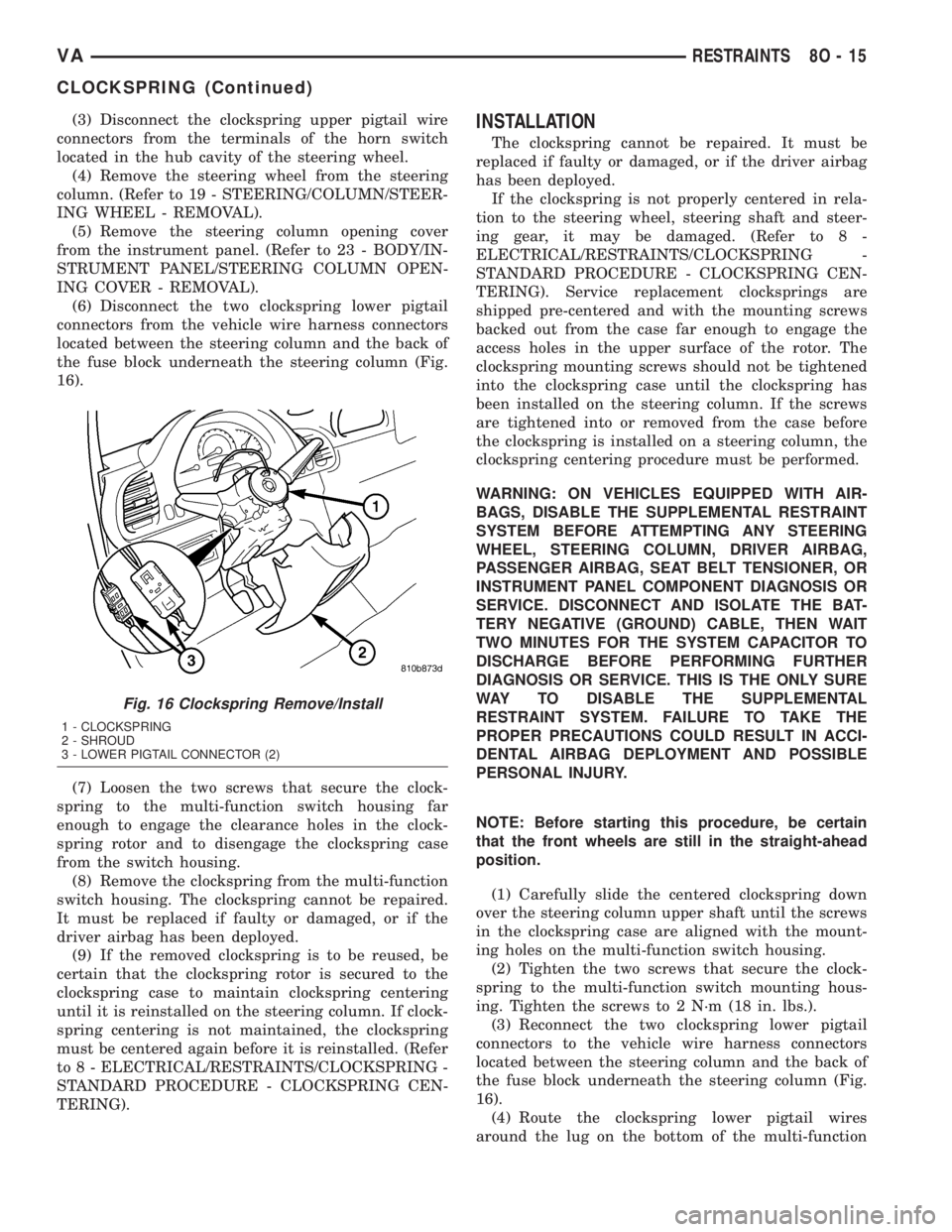
(6) Disconnect the two clockspring lower pigtail
connectors from the vehicle wire harness connectors
located between the steering column and the back of
the fuse block underneath the steering column (Fig.
16).
(7) Loosen the two screws that secure the clock-
spring to the multi-function switch housing far
enough to engage the clearance holes in the clock-
spring rotor and to disengage the clockspring case
from the switch housing.
(8) Remove the clockspring from the multi-function
switch housing. The clockspring cannot be repaired.
It must be replaced if faulty or damaged, or if the
driver airbag has been deployed.
(9) If the removed clockspring is to be reused, be
certain that the clockspring rotor is secured to the
clockspring case to maintain clockspring centering
until it is reinstalled on the steering column. If clock-
spring centering is not maintained, the clockspring
must be centered again before it is reinstalled. (Refer
to 8 - ELECTRICAL/RESTRAINTS/CLOCKSPRING -
STANDARD PROCEDURE - CLOCKSPRING CEN-
TERING).INSTALLATION
The clockspring cannot be repaired. It must be
replaced if faulty or damaged, or if the driver airbag
has been deployed.
If the clockspring is not properly centered in rela-
tion to the steering wheel, steering shaft and steer-
ing gear, it may be damaged. (Refer to 8 -
ELECTRICAL/RESTRAINTS/CLOCKSPRING -
STANDARD PROCEDURE - CLOCKSPRING CEN-
TERING). Service replacement clocksprings are
shipped pre-centered and with the mounting screws
backed out from the case far enough to engage the
access holes in the upper surface of the rotor. The
clockspring mounting screws should not be tightened
into the clockspring case until the clockspring has
been installed on the steering column. If the screws
are tightened into or removed from the case before
the clockspring is installed on a steering column, the
clockspring centering procedure must be performed.
WARNING: ON VEHICLES EQUIPPED WITH AIR-
BAGS, DISABLE THE SUPPLEMENTAL RESTRAINT
SYSTEM BEFORE ATTEMPTING ANY STEERING
WHEEL, STEERING COLUMN, DRIVER AIRBAG,
PASSENGER AIRBAG, SEAT BELT TENSIONER, OR
INSTRUMENT PANEL COMPONENT DIAGNOSIS OR
SERVICE. DISCONNECT AND ISOLATE THE BAT-
TERY NEGATIVE (GROUND) CABLE, THEN WAIT
TWO MINUTES FOR THE SYSTEM CAPACITOR TO
DISCHARGE BEFORE PERFORMING FURTHER
DIAGNOSIS OR SERVICE. THIS IS THE ONLY SURE
WAY TO DISABLE THE SUPPLEMENTAL
RESTRAINT SYSTEM. FAILURE TO TAKE THE
PROPER PRECAUTIONS COULD RESULT IN ACCI-
DENTAL AIRBAG DEPLOYMENT AND POSSIBLE
PERSONAL INJURY.
NOTE: Before starting this procedure, be certain
that the front wheels are still in the straight-ahead
position.
(1) Carefully slide the centered clockspring down
over the steering column upper shaft until the screws
in the clockspring case are aligned with the mount-
ing holes on the multi-function switch housing.
(2) Tighten the two screws that secure the clock-
spring to the multi-function switch mounting hous-
ing. Tighten the screws to 2 N´m (18 in. lbs.).
(3) Reconnect the two clockspring lower pigtail
connectors to the vehicle wire harness connectors
located between the steering column and the back of
the fuse block underneath the steering column (Fig.
16).
(4) Route the clockspring lower pigtail wires
around the lug on the bottom of the multi-function
Fig. 16 Clockspring Remove/Install
1 - CLOCKSPRING
2 - SHROUD
3 - LOWER PIGTAIL CONNECTOR (2)
VARESTRAINTS 8O - 15
CLOCKSPRING (Continued)
Page 285 of 1232
The longer blade is installed on the left (driver) side
of the windshield.
²Wiper Linkage- The wiper pivots are the only
visible components of the wiper linkage. The remain-
der of the linkage is concealed within the engine
compartment just behind the hood opening. The
wiper linkage module includes the two wiper drive
links, the wiper motor crank arm, the two wiper piv-
ots, and the linkage and motor mounting bracket.
²Wiper Motor- The wiper motor is secured to
the wiper linkage module bracket on the underside of
the cowl panel within the engine compartment. The
wiper motor output shaft and crank arm extend
through a clearance hole in the mounting bracket,
where they are connected to a crank arm that drives
the wiper linkage.
²Wiper Relay- The wiper relay is located in a
dedicated receptacle on the lower left surface of the
fuse block underneath the steering column behind
the fuse access panel and the steering column open-
ing panel.
²Wiper, Turn Signals, Engine Start Control
Module- The wiper, turn signals and engine start
control module is integral to the fuse block located
underneath the steering column. The fuse block is
concealed behind the fuse access panel and the steer-
ing column opening panel, where it is secured with
screws to the steering column. The wiper, turn sig-
nals and engine start control module contains the
intermittent wipe logic circuitry, which includes
active electronic elements that allow it to provide the
intermittent wipe delay and the wipe-after-wash fea-
tures of the intermittent wipe system based upon
numerous hard wired inputs, then provides the
proper programmed hard wired control output to
operate the wiper motor through the wiper relay.
Hard wired circuitry connects the wiper and
washer system components to the electrical system of
the vehicle. These hard wired circuits are integral to
several wire harnesses, which are routed throughout
the vehicle and retained by many different methods.
These circuits may be connected to each other, to the
vehicle electrical system and to the wiper and washer
system components through the use of a combination
of soldered splices, splice block connectors, and many
different types of wire harness terminal connectors
and insulators. Refer to the appropriate wiring infor-
mation. The wiring information includes wiring dia-
grams, proper wire and connector repair procedures,
further details on wire harness routing and reten-
tion, as well as pin-out and location views for the
various wire harness connectors, splices and grounds.OPERATING MODES
The components of the wiper and washer system
are designed to provide the following operating
modes:
²Continuous Wipe Mode- The two-speed wiper
motor, the internal circuitry of the multi-function
switch, and the wiper relay work in concert to pro-
vide two continuous wipe cycles, low speed or high
speed.
²Intermittent Wipe Mode- The internal cir-
cuitry of the multi-function switch, the intermittent
wipe circuitry of the wiper, turn signals and engine
start control module in the fuse block, and the wiper
relay work in concert to provide an intermittent wipe
mode with a single, fixed delay interval.
²Pulse Wipe Mode- The internal circuitry of
the multi-function switch and the wiper relay work
in concert to provide a pulse wipe mode that will
allow the wiper motor to be operated for a single,
complete wipe cycle.
²Washer Mode- When the washer system is
activated with the multi-function switch while the
wiper system is operating, washer fluid will be dis-
pensed onto the windshield glass through the washer
nozzles for as long as the washer pump/motor is
energized.
²Wipe-After-Wash Mode- The intermittent
wipe circuitry of the wiper, turn signals and engine
start control module in the fuse block, and the wiper
relay provide a wipe-after-wash feature. If the wipers
are turned Off, this feature will operate the washer
pump/motor and the wipers for as long as the washer
system is activated, then provide several additional
wipe cycles after the washer system is deactivated
before parking the wiper blades near the base of the
windshield.
OPERATION
The wiper and washer system is designed to pro-
vide the vehicle operator with a convenient, safe, and
reliable means of maintaining visibility through the
windshield glass. The various components of this sys-
tem are designed to convert electrical energy pro-
duced by the vehicle electrical system into the
mechanical action of the wiper blades to wipe the
outside surface of the glass, as well as into the
hydraulic action of the washer system to apply
washer fluid stored in an on-board reservoir to the
area of the glass to be wiped. When combined, these
components provide the means to effectively main-
tain clear visibility for the vehicle operator by remov-
ing excess accumulations of rain, snow, bugs, mud, or
other minor debris from the outside windshield glass
surface that might be encountered while driving the
vehicle under numerous types of inclement operating
conditions.
VAWIPERS/WASHERS 8R - 3
WIPERS/WASHERS (Continued)
Page 1214 of 1232
CIRCUIT BREAKER - OPERATION......8W-97-2
CIRCUIT INFORMATION - DESCRIPTION . 8W-01-5
CLAMP PLATES - INSTALLATION,
SPRING..............................2-8
CLAMP PLATES - REMOVAL, SPRING......2-8
CLASSIFICATION - STANDARD
PROCEDURE, INJECTOR...............14-22
CLEARANCE LAMP BULB -
INSTALLATION........................8L-8
CLEARANCE LAMP BULB - REMOVAL.....8L-8
CLEARANCE LAMP UNIT -
INSTALLATION........................8L-9
CLEARANCE LAMP UNIT - REMOVAL......8L-8
CLOCK - DESCRIPTION................8J-13
CLOCK - OPERATION..................8J-14
CLOCKSPRING - DESCRIPTION.........8O-12
CLOCKSPRING - INSTALLATION.........8O-15
CLOCKSPRING - OPERATION...........8O-13
CLOCKSPRING - REMOVAL............8O-14
CLOCKSPRING CENTERING - STANDARD
PROCEDURE........................8O-13
CLOGGED INDICATOR - DESCRIPTION,
FUEL FILTER........................8J-15
CLOGGED INDICATOR - OPERATION,
FUEL FILTER........................8J-15
CLUSTER - DESCRIPTION, INSTRUMENT . . . 8J-2
CLUSTER - DIAGNOSIS AND TESTING,
INSTRUMENT........................8J-7
CLUSTER - INSTALLATION, INSTRUMENT . . 8J-9
CLUSTER - INSTALLATION, TOP COVER . . . 23-62
CLUSTER - OPERATION, INSTRUMENT.....8J-5
CLUSTER - REMOVAL, INSTRUMENT......8J-7
CLUSTER - REMOVAL, TOP COVER......23-62
CLUSTER BEZEL - INSTALLATION........23-54
CLUSTER BEZEL - REMOVAL...........23-53
CLUTCH - ASSEMBLY, FREEWHEELING . . 21-107
CLUTCH - DESCRIPTION, A/C
COMPRESSOR........................24-8
CLUTCH - DESCRIPTION,
FREEWHEELING.....................21-105
CLUTCH - DISASSEMBLY,
FREEWHEELING.....................21-106
CLUTCH - INSTALLATION, FAN DRIVE
VISCOUS............................7-16
CLUTCH - OPERATION, A/C
COMPRESSOR........................24-8
CLUTCH - OPERATION, FREEWHEELING . . 21-105
CLUTCH - REMOVAL, FAN DRIVE
VISCOUS............................7-16
CLUTCH AIR GAP - STANDARD
PROCEDURE, COMPRESSOR............24-9
CLUTCH B1 - ASSEMBLY, HOLDING.....21-113
CLUTCH B1 - DISASSEMBLY, HOLDING . . 21-112
CLUTCH B2 - ASSEMBLY, HOLDING.....21-116
CLUTCH B2 - DISASSEMBLY, HOLDING . . 21-115
CLUTCH BREAK-IN - STANDARD
PROCEDURE, COMPRESSOR............24-9
CLUTCH COIL - DIAGNOSIS AND
TESTING, COMPRESSOR...............24-12
CLUTCH K1 - ASSEMBLY, DRIVING.......21-75
CLUTCH K1 - DISASSEMBLY, DRIVING....21-74
CLUTCH K2 - ASSEMBLY, DRIVING.......21-78
CLUTCH K2 - DISASSEMBLY, DRIVING....21-76
CLUTCH K3 - ASSEMBLY, DRIVING.......21-80
CLUTCH K3 - DISASSEMBLY, DRIVING....21-80
CLUTCH/COIL - INSPECTION,
COMPRESSOR.......................24-10
CLUTCHES - DESCRIPTION, DRIVING.....21-72
CLUTCHES - DESCRIPTION, HOLDING . . . 21-111
CLUTCHES - OPERATION, DRIVING......21-72
CLUTCHES - OPERATION, HOLDING.....21-112
CODES - SPECIFICATIONS, PAINT........23-74
COIL - DIAGNOSIS AND TESTING,
COMPRESSOR CLUTCH...............24-12
COLUMN OPENING COVER -
INSTALLATION, STEERING.............23-66
COLUMN OPENING COVER - REMOVAL,
STEERING..........................23-66
COMPRESSION TESTING ENGINE -
STANDARD PROCEDURE.................9-3
COMPRESSOR - DESCRIPTION, A/C......24-49
COMPRESSOR - INSTALLATION, A/C
.....24-51
COMPRESSOR - OPERATION, A/C
........24-49
COMPRESSOR - REMOVAL, A/C
.........24-50
COMPRESSOR CLUTCH - DESCRIPTION,
A/C
................................24-8
COMPRESSOR CLUTCH - OPERATION,
A/C
................................24-8COMPRESSOR CLUTCH AIR GAP -
STANDARD PROCEDURE................24-9
COMPRESSOR CLUTCH BREAK-IN -
STANDARD PROCEDURE................24-9
COMPRESSOR CLUTCH COIL -
DIAGNOSIS AND TESTING.............24-12
COMPRESSOR CLUTCH/COIL -
INSPECTION........................24-10
COMPRESSOR NOISE - DIAGNOSIS AND
TESTING...........................24-49
CONDENSER - DESCRIPTION, A/C.......24-52
CONDENSER - INSTALLATION, A/C.......24-52
CONDENSER - OPERATION, A/C.........24-52
CONDENSER - REMOVAL, A/C..........24-52
CONDITIONER - DESCRIPTION, HEATER
AND AIR ............................24-1
CONDITIONER - OPERATION, HEATER
AND AIR ............................24-2
CONNECTING FUEL LINES - STANDARD
PROCEDURE, DISCONNECTING...........14-2
CONNECTING ROD - DESCRIPTION,
PISTON.............................9-40
CONNECTING RODS - STANDARD
PROCEDURE, CHECKING AND
REPAIRING..........................9-40
CONNECTOR - INSTALLATION........8W-01-9
CONNECTOR - REMOVAL............8W-01-8
CONNECTOR, GROUND AND SPLICE
INFORMATION - DESCRIPTION........8W-01-5
CONNECTOR/GROUND/SPLICE LOCATION
- DESCRIPTION....................8W-91-1
CONTACT - DESCRIPTION, PARK/
NEUTRAL..........................21-139
CONTACT - OPERATION, PARK/NEUTRAL . 21-140
CONTAMINATION - DIAGNOSIS AND
TESTING, BRAKE FLUID................5-14
CONTAMINATION - DIAGNOSIS AND
TESTING, FLUID....................21-102
CONTINUITY - STANDARD PROCEDURE,
TESTING.........................8W-01-8
CONTROL ARM - INSTALLATION, LOWER . . . 2-6
CONTROL ARM - REMOVAL, LOWER.......2-6
CONTROL INDICATOR - DESCRIPTION,
TRACTION..........................8J-24
CONTROL INDICATOR - OPERATION,
TRACTION..........................8J-24
CONTROL MALFUNCTION INDICATOR -
DESCRIPTION, TRACTION..............8J-25
CONTROL MALFUNCTION INDICATOR -
OPERATION, TRACTION................8J-25
CONTROL MODULE - DESCRIPTION......24-24
CONTROL MODULE - DESCRIPTION,
AIRBAG.............................8O-8
CONTROL MODULE - DESCRIPTION,
ENGINE.............................8E-3
CONTROL MODULE - DESCRIPTION,
TRANSMISSION.......................8E-5
CONTROL MODULE - DIAGNOSIS AND
TESTING...........................24-24
CONTROL MODULE - INSTALLATION.....24-25
CONTROL MODULE - INSTALLATION,
AIRBAG............................8O-11
CONTROL MODULE - INSTALLATION,
ENGINE.............................8E-4
CONTROL MODULE - OPERATION.......24-24
CONTROL MODULE - OPERATION,
AIRBAG.............................8O-9
CONTROL MODULE - OPERATION,
TRANSMISSION.......................8E-5
CONTROL MODULE - REMOVAL.........24-24
CONTROL MODULE - REMOVAL, AIRBAG . 8O-10
CONTROL MODULE - REMOVAL, ENGINE . . . 8E-4
CONTROLLER - INSTALLATION, ALB......5-15
CONTROLLER - REMOVAL, ALB..........5-15
CONTROLLER ANTILOCK BRAKE -
DESCRIPTION........................8E-3
CONTROLLER ANTILOCK BRAKE -
INSTALLATION........................8E-3
CONTROLLER ANTILOCK BRAKE -
REMOVAL...........................8E-3
CONVERTER - DESCRIPTION, TORQUE . . . 21-141
CONVERTER - INSTALLATION, CATALYTIC . . 11-3
CONVERTER - INSTALLATION, TORQUE
. . 21-146
CONVERTER - OPERATION, TORQUE
....21-143
CONVERTER - REMOVAL, CATALYTIC
......11-3
CONVERTER - REMOVAL, TORQUE
......21-146
CONVERTER HUB SEAL - INSTALLATION,
TORQUE
...........................21-147CONVERTER HUB SEAL - REMOVAL,
TORQUE...........................21-147
COOLANT - DESCRIPTION...............7-9
COOLANT - DESCRIPTION, ENGINE........0-1
COOLANT - DESCRIPTION, HOAT..........0-2
COOLANT - STANDARD PROCEDURE,
ADDING ADDITIONAL..................7-11
COOLANT LEVEL SENSOR -
INSTALLATION........................7-13
COOLANT LEVEL SENSOR - REMOVAL.....7-13
COOLANT LOW INDICATOR -
DESCRIPTION.......................8J-14
COOLANT LOW INDICATOR - OPERATION . 8J-14
COOLANT PUMP - DESCRIPTION,
ELECTRIC..........................24-57
COOLANT PUMP - INSTALLATION,
ELECTRIC..........................24-57
COOLANT PUMP - OPERATION,
ELECTRIC..........................24-57
COOLANT PUMP - REMOVAL, ELECTRIC . . 24-57
COOLANT TEMP SENSOR -
DESCRIPTION, ENGINE.................7-14
COOLANT TEMP SENSOR -
INSTALLATION, ENGINE................7-15
COOLANT TEMP SENSOR - REMOVAL,
ENGINE.............................7-14
COOLANT THERMOSTAT -
INSTALLATION, ENGINE................7-16
COOLANT THERMOSTAT - REMOVAL,
ENGINE.............................7-15
COOLER & LINES - INSTALLATION, OIL....9-50
COOLER & LINES - REMOVAL, OIL.......9-50
COOLER AND PLUMBING - CLEANING,
CHARGE AIR.........................11-5
COOLER AND PLUMBING -
DESCRIPTION, CHARGE AIR.............11-4
COOLER AND PLUMBING - INSPECTION,
CHARGE AIR.........................11-5
COOLER AND PLUMBING -
INSTALLATION, CHARGE AIR............11-5
COOLER AND PLUMBING - OPERATION,
CHARGE AIR.........................11-4
COOLER AND PLUMBING - REMOVAL,
CHARGE AIR.........................11-5
COOLER SYSTEM - LEAKS - DIAGNOSIS
AND TESTING, CHARGE AIR.............11-4
COOLER TUBE - INSTALLATION, FLUID . . . 19-14
COOLER TUBE - INSTALLATION, RETURN
HOSE FROM GEAR TO................19-15
COOLER TUBE - INSTALLATION, RETURN
LINE FROM PUMP TO.................19-15
COOLER TUBE - REMOVAL, FLUID.......19-14
COOLER TUBE - REMOVAL, RETURN
HOSE FROM GEAR TO................19-15
COOLER TUBE - REMOVAL, RETURN
LINE FROM PUMP TO.................19-15
COOLING SYSTEM - DIAGNOSIS AND
TESTING.............................7-2
COOLING SYSTEM - OPERATION..........7-1
COOLING SYSTEM - STANDARD
PROCEDURE, DRAINING................7-12
COOLING SYSTEM - STANDARD
PROCEDURE, REFILLING................7-12
COOLING SYSTEM LEAKS - DIAGNOSIS
AND TESTING........................7-10
COOLING SYSTEM REQUIREMENTS -
DESCRIPTION........................24-1
CORE - DESCRIPTION, HEATER.........24-57
CORE - INSTALLATION, HEATER.........24-58
CORE - OPERATION, HEATER...........24-57
CORE - REMOVAL, HEATER............24-58
CORE AND OIL GALLERY PLUGS -
STANDARD PROCEDURE, REPLACING
ENGINE.............................9-34
COVER - CLUSTER - INSTALLATION, TOP . 23-62
COVER - CLUSTER - REMOVAL, TOP.....23-62
COVER - INSTALLATION, CYLINDER
HEAD FRONT.........................9-26
COVER - INSTALLATION, ENGINE..........9-7
COVER - INSTALLATION, STEERING
COLUMN OPENING...................23-66
COVER - INSTALLATION, TIMING CHAIN
. . . 9-60
COVER - INSTALLATION, TOP
...........23-65
COVER - REMOVAL, CYLINDER HEAD
FRONT
..............................9-23
COVER - REMOVAL, ENGINE
..............9-4
COVER - REMOVAL, STEERING COLUMN
OPENING
...........................23-66
4 INDEXVA
Description Group-Page Description Group-Page Description Group-Page