2005 MERCEDES-BENZ SPRINTER change wheel
[x] Cancel search: change wheelPage 34 of 1232
SPRING
DESCRIPTION
The rear suspension system uses a multi-leaf
springs and a solid drive axle. The forward end of the
springs are mounted to the body rail hangers
through rubber bushings. The rearward end of the
springs are attached to the body by the use of shack-
les. The spring and shackles use rubber bushings.
OPERATION
The springs control ride quality and maintain vehi-
cle ride height. The shackles allow the springs to
change their length as the vehicle moves over various
road conditions.
REMOVAL
REMOVAL - (SRW)
(1) Raise and support the vehicle.
(2) Support the rear axle.
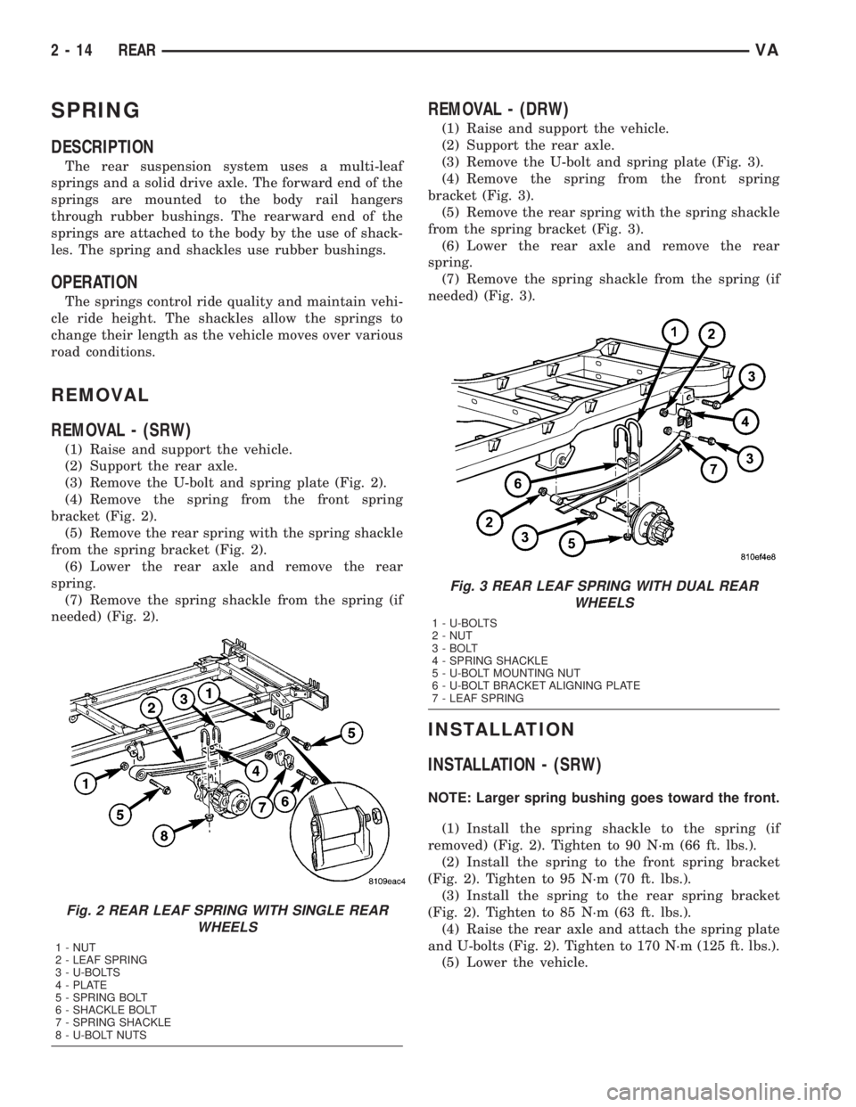
(3) Remove the U-bolt and spring plate (Fig. 2).
(4) Remove the spring from the front spring
bracket (Fig. 2).
(5) Remove the rear spring with the spring shackle
from the spring bracket (Fig. 2).
(6) Lower the rear axle and remove the rear
spring.
(7) Remove the spring shackle from the spring (if
needed) (Fig. 2).
REMOVAL - (DRW)
(1) Raise and support the vehicle.
(2) Support the rear axle.
(3) Remove the U-bolt and spring plate (Fig. 3).
(4) Remove the spring from the front spring
bracket (Fig. 3).
(5) Remove the rear spring with the spring shackle
from the spring bracket (Fig. 3).
(6) Lower the rear axle and remove the rear
spring.
(7) Remove the spring shackle from the spring (if
needed) (Fig. 3).
INSTALLATION
INSTALLATION - (SRW)
NOTE: Larger spring bushing goes toward the front.
(1) Install the spring shackle to the spring (if
removed) (Fig. 2). Tighten to 90 N´m (66 ft. lbs.).
(2) Install the spring to the front spring bracket
(Fig. 2). Tighten to 95 N´m (70 ft. lbs.).
(3) Install the spring to the rear spring bracket
(Fig. 2). Tighten to 85 N´m (63 ft. lbs.).
(4) Raise the rear axle and attach the spring plate
and U-bolts (Fig. 2). Tighten to 170 N´m (125 ft. lbs.).
(5) Lower the vehicle.
Fig. 2 REAR LEAF SPRING WITH SINGLE REAR
WHEELS
1 - NUT
2 - LEAF SPRING
3 - U-BOLTS
4 - PLATE
5 - SPRING BOLT
6 - SHACKLE BOLT
7 - SPRING SHACKLE
8 - U-BOLT NUTS
Fig. 3 REAR LEAF SPRING WITH DUAL REAR
WHEELS
1 - U-BOLTS
2 - NUT
3 - BOLT
4 - SPRING SHACKLE
5 - U-BOLT MOUNTING NUT
6 - U-BOLT BRACKET ALIGNING PLATE
7 - LEAF SPRING
2 - 14 REARVA
Page 42 of 1232
DRIVELINE VIBRATION
Drive Condition Possible Cause Correction
Propeller Shaft Noise 1) Undercoating or other foreign
material on shaft.1) Clean exterior of shaft and wash
with solvent.
2) Loose U-joint clamp screws. 2) Install new clamps and screws
and tighten to proper torque.
3) Loose or bent U-joint yoke or
excessive runout.3) Install new yoke.
4) Incorrect driveline angularity. 4) Measure and correct driveline
angles.
5) Rear spring center bolt not in
seat.5) Loosen spring u-bolts and seat
center bolt.
6) Worn U-joint bearings. 6) Install new U-joint.
7) Propeller shaft damaged or out
of balance.7) Installl new propeller shaft.
8) Broken rear spring. 8) Install new rear spring.
9) Excessive runout or unbalanced
condition.9) Re-index propeller shaft, test,
and evaluate.
10) Excessive drive pinion gear
shaft runout.10) Re-index propeller shaft and
evaluate.
11) Excessive axle yoke deflection. 11) Inspect and replace yoke if
necessary.
12) Excessive transfer case runout. 12) Inspect and repair as necessary.
Universal Joint Noise 1) Loose U-joint clamp screws. 1) Install new clamps and screws
and tighten to proper torque.
2) Lack of lubrication. 2) Replace as U-joints as
necessary.
PROPELLER SHAFT BALANCE
NOTE: Removing and indexing the propeller shaft
180É relative to the yoke may eliminate some vibra-
tions.
If propeller shaft is suspected of being out of bal-
ance, verify with the following procedure:
(1) Place vehicle in netrual.
(2) Raise and support the vehicle by the axles as
level as possible.
(3) Clean all foreign material from propeller shaft
and universal joints.
(4) Inspect propeller shaft for missing balance
weights, broken welds, and bent areas.
NOTE: If propeller shaft is bent, it must be replaced.
(5) Inspect universal joints for wear, properly
installed and correct alignment with the shaft.
(6) Check universal joint clamp screws torque.
(7) Remove wheels and tires. Install wheel lug
nuts to retain the brake drums/rotors.(8) Mark and number propeller shaft six inches
from the pinion yoke end at four positions 90É apart.
(9) Run and accelerate the vehicle until vibration
occurs. Note intensity and speed the vibration
occurred. Stop the engine.
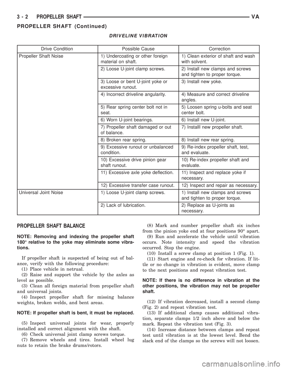
(10) Install a screw clamp at position 1 (Fig. 1).
(11) Start engine and re-check for vibration. If lit-
tle or no change in vibration is evident, move clamp
to the next positions and repeat vibration test.
NOTE: If there is no difference in vibration at the
other positions, the vibration may not be propeller
shaft.
(12) If vibration decreased, install a second clamp
(Fig. 2) and repeat vibration test.
(13) If additional clamp causes additional vibra-
tion, separate clamps 1/2 inch above and below the
mark. Repeat the vibration test (Fig. 3).
(14) Increase distance between clamps and repeat
test until vibration is at the lowest level. Bend the
slack end of the clamps so the screws will not loosen.
3 - 2 PROPELLER SHAFTVA
PROPELLER SHAFT (Continued)
Page 50 of 1232
REAR AXLE
TABLE OF CONTENTS
page page
REAR AXLE
DESCRIPTION.........................10
OPERATION...........................10
DIAGNOSIS AND TESTING................10
STANDARD PROCEDURE - DRAIN AND FILL . . 11
REMOVAL.............................11
INSTALLATION.........................12
SPECIFICATIONS.......................13
SPECIAL TOOLS.......................14
AXLE SHAFTS
REMOVAL.............................15
INSTALLATION.........................15AXLE BEARINGS/SEALS
REMOVAL.............................17
INSTALLATION.........................17
AXLE SHAFTS - DUAL REAR WHEELS
REMOVAL.............................19
INSTALLATION.........................19
AXLE HUB BEARINGS/SEALS
REMOVAL.............................20
INSTALLATION.........................20
PINION SEAL
REMOVAL.............................22
INSTALLATION.........................22
REAR AXLE
DESCRIPTION
The axle housings consist of a cast iron center sec-
tion with axle tubes extending from either side. The
tubes are pressed into and welded to the differential
housing to form a one-piece axle housing. The SRW
axle has semi-floating axle shafts, DRW has full-
floating axle shafts.
NOTE: Axle seals, axle bearings, pinion seal and
differential cover are the only serviceble compo-
nents. If differential is damaged/noisy the axle must
be replaced.
OPERATION
The axle receives power from the transmission
through the rear propeller shaft. The rear propeller
shaft is connected to the pinion gear which rotates
the differential through the gear mesh with the ring
gear bolted to the differential case. The engine power
is transmitted to the axle shafts through the pinion
mate and side gears. The side gears are splined to
the axle shafts.
DIAGNOSIS AND TESTING
NOTE: Axle seals, axle bearings, pinion seals and
differential cover are the only serviceble compo-
nents. If differential is damaged/noisy the axle must
be replaced.
GEAR NOISE
Axle gear noise can be caused by insufficient lubri-
cant, incorrect backlash, incorrect pinion depth, tooth
contact, worn/damaged gears, or the carrier housing
not having the proper offset and squareness.
Gear noise usually happens at a specific speed
range. The noise can also occur during a specific type
of driving condition. These conditions are accelera-
tion, deceleration, coast, or constant load.
When road testing, first warm-up the axle fluid by
driving the vehicle at least 5 miles and then acceler-
ate the vehicle to the speed range where the noise is
the greatest. Shift out-of-gear and coast through the
peak-noise range. If the noise stops or changes
greatly:
²Check for insufficient lubricant.
²Incorrect ring gear backlash.
²Gear damage.
Differential side gears and pinions can be checked
by turning the vehicle. They usually do not cause
noise during straight-ahead driving when the gears
are unloaded. The side gears are loaded during vehi-
cle turns. A worn pinion shaft can also cause a snap-
ping or a knocking noise.
BEARING NOISE
The axle shaft, differential and pinion bearings can
all produce noise when worn or damaged. Bearing
noise can be either a whining, or a growling sound.
Pinion bearingshave a constant-pitch noise. This
noise changes only with vehicle speed. Pinion bearing
noise will be higher pitched because it rotates at a
faster rate. Drive the vehicle and load the differen-
tial. If bearing noise occurs, the rear pinion bearing
is the source of the noise. If the bearing noise is
3 - 10 REAR AXLEVA
Page 51 of 1232
heard during a coast, the front pinion bearing is the
source.
Differential bearings usually produce a low pitch
noise. Differential bearing noise is similar to pinion
bearing noise. The pitch of differential bearing noise
is also constant and varies only with vehicle speed.
Axle shaft bearingsproduce noise and vibration
when worn or damaged. The noise generally changes
when the bearings are loaded. Road test the vehicle.
Turn the vehicle sharply to the left and to the right.
This will load the bearings and change the noise
level. Where axle bearing damage is slight, the noise
is usually not noticeable at speeds above 30 mph.
LOW SPEED KNOCK
Low speed knock is generally caused by a worn
U-joint or by worn side-gear thrust washers. A worn
pinion shaft bore will also cause low speed knock.
VIBRATION
Vibration at the rear of the vehicle is usually
caused by a:
²Damaged drive shaft.
²Missing drive shaft balance weight(s).
²Worn or out-of-balance wheels.
²Loose wheel lug nuts.
²Worn U-joint(s).
²Loose/broken springs.
²Damaged axle shaft bearing(s).
²Loose pinion gear nut.
²Excessive pinion yoke run out.
²Bent axle shaft(s).
Check for loose or damaged front-end components
or engine/transmission mounts. These components
can contribute to what appears to be a rearend vibra-
tion. Do not overlook engine accessories, brackets
and drive belts.
NOTE: All driveline components should be exam-
ined before starting any repair.
DRIVELINE SNAP
A snap or clunk noise when the vehicle is shifted
into gear (or the clutch engaged), can be caused by:
²High engine idle speed.
²Transmission shift operation.
²Loose engine/transmission/transfer case mounts.
²Worn U-joints.
²Loose spring mounts.
²Loose pinion gear nut and yoke.
²Excessive ring gear backlash.
²Excessive side gear to case clearance.
The source of a snap or a clunk noise can be deter-
mined with the assistance of a helper. Raise the vehi-
cle on a hoist with the wheels free to rotate. Instruct
the helper to shift the transmission into gear. Listenfor the noise, a mechanics stethoscope is helpful in
isolating the source of a noise.
STANDARD PROCEDURE - DRAIN AND FILL
NOTE: Drain oil when warm.
(1) Clean area around oil fill plug and drain plug.
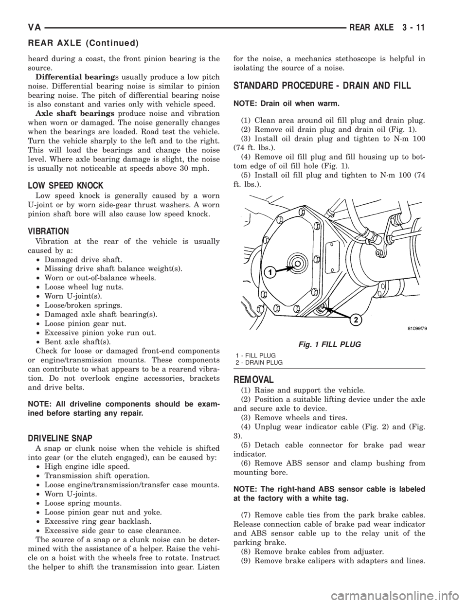
(2) Remove oil drain plug and drain oil (Fig. 1).
(3) Install oil drain plug and tighten to N´m 100
(74 ft. lbs.).
(4) Remove oil fill plug and fill housing up to bot-
tom edge of oil fill hole (Fig. 1).
(5) Install oil fill plug and tighten to N´m 100 (74
ft. lbs.).
REMOVAL
(1) Raise and support the vehicle.
(2) Position a suitable lifting device under the axle
and secure axle to device.
(3) Remove wheels and tires.
(4) Unplug wear indicator cable (Fig. 2) and (Fig.
3).
(5) Detach cable connector for brake pad wear
indicator.
(6) Remove ABS sensor and clamp bushing from
mounting bore.
NOTE: The right-hand ABS sensor cable is labeled
at the factory with a white tag.
(7) Remove cable ties from the park brake cables.
Release connection cable of brake pad wear indicator
and ABS sensor cable up to the relay unit of the
parking brake.
(8) Remove brake cables from adjuster.
(9) Remove brake calipers with adapters and lines.
Fig. 1 FILL PLUG
1 - FILL PLUG
2 - DRAIN PLUG
VAREAR AXLE 3 - 11
REAR AXLE (Continued)
Page 68 of 1232
A worn, damaged wheel bearing or suspension
component are further causes of pull. A damaged
front tire (bruised, ply separation) can also cause
pull.
A common and frequently misdiagnosed pull condi-
tion is where direction of pull changes after a few
stops. The cause is a combination of brake drag fol-
lowed by fade at one of the brake units.
As the dragging brake overheats, efficiency is so
reduced that fade occurs. Since the opposite brake
unit is still functioning normally, its braking effect is
magnified. This causes pull to switch direction in
favor of the normally functioning brake unit.
An additional point when diagnosing a change in
pull condition concerns brake cool down. Remember
that pull will return to the original direction, if the
dragging brake unit is allowed to cool down (and is
not seriously damaged).
REAR BRAKE GRAB OR PULL
Rear grab or pull is usually caused by improperly
adjusted or seized parking brake cables, contami-
nated lining, bent or binding shoes and support
plates, or improperly assembled components. This is
particularly true when only one rear wheel is
involved. However, when both rear wheels are
affected, the master cylinder or proportioning valve
could be at fault.
BRAKES DO NOT HOLD AFTER DRIVING THROUGH DEEP
WATER PUDDLES
This condition is generally caused by water soaked
lining. If the lining is only wet, it can be dried by
driving with the brakes very lightly applied for a
mile or two. However, if the lining is both soaked and
dirt contaminated, cleaning and/or replacement will
be necessary.
BRAKE LINING CONTAMINATION
Brake lining contamination is mostly a product of
leaking calipers or worn seals, driving through deep
water puddles, or lining that has become covered
with grease and grit during repair. Contaminated lin-
ing should be replaced to avoid further brake prob-
lems.
WHEEL AND TIRE PROBLEMS
Some conditions attributed to brake components
may actually be caused by a wheel or tire problem.
A damaged wheel can cause shudder, vibration and
pull. A worn or damaged tire can also cause pull.
Severely worn tires with very little tread left can
produce a grab-like condition as the tire loses and
recovers traction. Flat-spotted tires can cause vibra-
tion and generate shudder during brake operation. A
tire with internal damage such as a severe bruise,
cut, or ply separation can cause pull and vibration.BRAKE NOISES
Some brake noise is common with rear drum
brakes and on some disc brakes during the first few
stops after a vehicle has been parked overnight or
stored. This is primarily due to the formation of trace
corrosion (light rust) on metal surfaces. This light
corrosion is typically cleared from the metal surfaces
after a few brake applications causing the noise to
subside.
BRAKE SQUEAK/SQUEAL
Brake squeak or squeal may be due to linings that
are wet or contaminated with brake fluid, grease, or
oil. Glazed linings and rotors with hard spots can
also contribute to squeak. Dirt and foreign material
embedded in the brake lining will also cause squeak/
squeal.
A very loud squeak or squeal is frequently a sign of
severely worn brake lining. If the lining has worn
through to the brake pads in spots, metal-to-metal
contact occurs. If the condition is allowed to continue,
rotors can become so scored that replacement is nec-
essary.
BRAKE CHATTER
Brake chatter is usually caused by loose or worn
components, or glazed/burnt lining. Rotors with hard
spots can also contribute to chatter. Additional causes
of chatter are out-of-tolerance rotors, brake lining not
securely attached to the shoes, loose wheel bearings
and contaminated brake lining.
THUMP/CLUNK NOISE
Thumping or clunk noises during braking are fre-
quentlynotcaused by brake components. In many
cases, such noises are caused by loose or damaged
steering, suspension, or engine components. However,
calipers that bind on the slide surfaces can generate
a thump or clunk noise.
STANDARD PROCEDURE
STANDARD PROCEDURE - MANUAL BLEEDING
Use Mopar brake fluid, or an equivalent quality
fluid meeting SAE and DOT 4 standards only. Use
fresh, clean fluid from a sealed container at all times.
(1) Remove reservoir filler caps and fill reservoir.
(2) If calipers, or wheel cylinders were overhauled,
open all caliper and wheel cylinder bleed screws.
Then close each bleed screw as fluid starts to drip
from it. Top off master cylinder reservoir once more
before proceeding.
(3) Attach one end of bleed hose to bleed screw
and insert opposite end in glass container partially
filled with brake fluid (Fig. 1). Be sure end of bleed
hose is immersed in fluid.
5 - 4 BRAKES - BASEVA
BRAKES - BASE (Continued)
Page 125 of 1232
TRANSMISSION CONTROL
MODULE
DESCRIPTION
The transmission control module (TCM) receives,
processes and sends various digital and analog sig-
nals related to the automatic transmission. In addi-
tion, it processes information received from other
vehicle systems, such as engine torque and speed,
accelerator pedal position, wheel speed, kick-down
switch, traction control information, etc.
The TCM is located under the driver's seat and is
connected to other control modules via a CAN bus. It
controls all shift functions to achieve smooth shift
comfort in all driving situations considering:
²Vehicle speed.
²Transmission status.
²Position of selector lever.
²Selected shift range.
²CAN signals.
²Engine Status.Engine speed limits may be reached in all gears
with full throttle or in kick-down operation. In for-
ward driving, the shift range of the forward gears
can be adjusted by the operator by tipping the selec-
tor lever to the left or right (AutoStick). However, the
TCM features a downshift inhibitor to prevent the
engine from overspeeding.
OPERATION
The transmission control module (TCM) deter-
mines the current operating conditions of the vehicle
and controls the shifting process for shift comfort and
driving situations. It receives this operating data
from sensors and broadcast messages from other
modules.
The TCM uses inputs from several sensors that are
directly hardwired to the controller and it uses sev-
eral indirect inputs that are used to control shifts.
This information is used to actuate the proper sole-
noids in the valve body to achieve the desired gear.
The shift lever assembly (SLA) has several items
that are monitored by the TCM to calculate shift
lever position. The reverse light switch, an integral
part of the SLA, controls the reverse light relay con-
trol circuit. The Brake/Transmission Shift Interlock
(BTSI) solenoid and the park lockout solenoid (also
part of the SLA) are controlled by the TCM.
The ECM and ABS broadcast messages over the
controller area network (CAN C) bus for use by the
TCM. The TCM uses this information, with other
inputs, to determine the transmission operating con-
ditions.
The TCM:
²determines the momentary operating conditions
of the vehicle.
²controls all shift processes.
²considers shift comfort and the driving situation.
The TCM controls the solenoid valves for modulat-
ing shift pressures and gear changes. Relative to the
torque being transmitted, the required pressures are
calculated from load conditions, engine rpm, vehicle
speed, and ATF temperature.
The following functions are contained in the TCM:
²Shift Program
²Downshift Safety
²Torque Converter Lock-Up Clutch.
²Adaptation.
This transmission does not have a TCM relay.
Power is supplied to the SLA and the TCM directly
from the ignition.
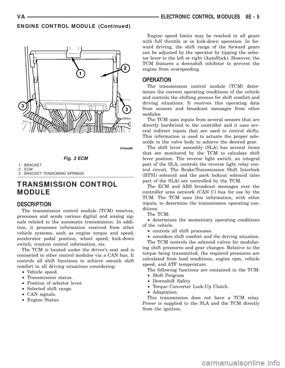
Fig. 3 ECM
1 - BRACKET
2 - ECM
3 - BRACKET TENSIONING SPRINGS
VAELECTRONIC CONTROL MODULES 8E - 5
ENGINE CONTROL MODULE (Continued)
Page 126 of 1232
The TCM continuously checks for electrical prob-
lems, mechanical problems, and some hydraulic prob-
lems. When a problem is sensed, the TCM stores a
diagnostic trouble code (DTC). Some of these codes
cause the transmission to go into9Limp-In9or
9default9mode. Some DTCs cause permanent
Limp-In and others cause temporary Limp-In. The
NAG1 defaults in the current gear position if a DTC
is detected, then after a key cycle the transmission
will go into Limp-in, which is mechanical 2nd gear.
Some DTCs may allow the transmission to resume
normal operation (recover) if the detected problem
goes away. A permanent Limp-In DTC will recover
when the key is cycled, but if the same DTC is
detected for three key cycles the system will not
recover and the DTC must be cleared from the TCM
with the DRBIIItscan tool.
TCM SIGNALS
The TCM registers one part of the input signals by
direct inputs, the other part by CAN C bus. In addi-
tion to the direct control of the actuators, the TCM
sends various output signals by CAN C bus to other
control modules.
Selector Lever Position
The TCM monitors the SLA for all shift lever posi-
tions via the CAN bus.
ATF Temperature Sensor
The ATF temperature sensor is a positive temper-
ature co-efficient (PTC) thermistor. It measures the
temperature of the transmission fluid and is a direct
input signal for the TCM. The temperature of the
ATF has an influence on the shifttime and resulting
shift quality. As the temperature rises, resistance
rises, and therefore, the probing voltage is decreas-
ing. Because of its registration, the shifting process
can be optimized in all temperature ranges.
The ATF temperature sensor is wired in series
with the park/neutral contact. The temperature sig-
nal is transmitted to the TCM only when the reed
contact of the park/neutral contact is closed because
the TCM only reads ATF temperature while in any
forward gear, or REVERSE. When the transmission
is in PARK or NEUTRAL, the TCM will substitute
the engine temperature for the ATF temperature.
Starter Interlock
The TCM monitors a contact switch wired in series
with the transmission temperature sensor to deter-
mine PARK and NEUTRAL positions. The contact
switch is open in PARK and NEUTRAL. The TCM
senses transmission temperature as high (switch
supply voltage), confirming switch status as open.
The TCM then broadcasts a message over CAN bus
to confirm switch status. The PCM receives thisinformation and allows operation of the starter cir-
cuit.
N2 and N3 Speed Sensors
The N2 and N3 Input Speed Sensors are two Hall-
effect speed sensors that are mounted internally in
the transmission and are used by the TCM to calcu-
late the transmission's input speed. Since the input
speed cannot be measured directly, two of the drive
elements are measured. Two input speed sensors
were required because both drive elements are not
active in all gears.
CAN C Bus Indirect Input Signals
A 2.5-volt bias (operating voltage) is present on the
CAN C bus any time the ignition switch is in the
RUN position. Both the TCM and the ABS apply this
bias. On this vehicle, the CAN C bus is used for mod-
ule data exchange only. The indirect inputs used on
the NAG1 electronic control system are:
²Wheel Speed Sensors.
²Brake Switch.
²Engine RPM.
²Engine Temperature.
²Cruise Control Status.
²Gear Limit Request.
²Throttle Position - 0% at idle, 100% at WOT. If
open, TCM assumes idle (0% throttle opening).
²Odometer Mileage
²Maximum Effective Torque.
²Engine in Limp-In Mode/Mileage Where DTC
Was Set.
BRAKE TRANSMISSION SHIFT INTERLOCK (BTSI)
The BTSI solenoid prevents shifting out of the
PARK position until the ignition key is in the RUN
position and the brake pedal is pressed. The TCM
controls the ground while the ignition switch supplies
power to the BTSI solenoid. The PCM monitors the
brake switch and broadcasts brake switch status
messages over the CAN C bus. If the park brake is
depressed and there is power (Run/Start) to SLA, the
BTSI solenoid deactivates.
SHIFT SCHEDULES
The basic shift schedule includes up and down-
shifts for all five gears. The TCM adapts the shift
program according to driving style, accelerator pedal
position and deviation of vehicle speed. Influencing
factors are:
²Road Conditions.
²Incline, Decline and Altitude.
²Trailer Operation, Loading.
²Engine Coolant Temperature.
²Cruise Control Operation.
²Sporty Driving Style.
8E - 6 ELECTRONIC CONTROL MODULESVA
TRANSMISSION CONTROL MODULE (Continued)
Page 202 of 1232
FRONT FOG LAMPS
Vehicles equipped with optional front fog lamps
have a front fog lamp relay installed in a relay
bracket located below the forward edge of the driver
side front seat cushion within the driver side front
seat riser, a fog lamp switch installed in the cluster
bezel on the instrument panel outboard of the steer-
ing column, and a fog lamp bulb installed in each of
the two front lamp units. The front fog lamps have a
path to ground at all times through their connection
to the vehicle wire harness. The headlamp switch cir-
cuitry of the left (lighting) control stalk of the multi-
function switch controls front fog lamp operation by
providing battery current to the front fog lamp relay
only when the low beam headlamps are selected. The
fog lamp switch controls front fog lamp operation by
energizing or de-energizing the front fog lamp relay
control coil.
HAZARD WARNING LAMPS
With the hazard switch in the On position, the
hazard switch button illuminates and the right and
left turn signal indicators as well as the right and
left turn signal lamps begin to flash on and off. When
the hazard warning system is activated, the hazard
switch circuitry within the multi-function switch and
the wipers, turn signals and engine start control
module electronic circuitry within the fuse block will
repeatedly energize and de-energize the turn signal
relay located in the fuse block. The turn signal relay
switches battery current from a fused B(+) fuse in
the fuse block to the turn signal indicators and the
turn signal lamps. The flashing of the hazard switch
button illumination lamp is also controlled by the
output from the turn signal relay.
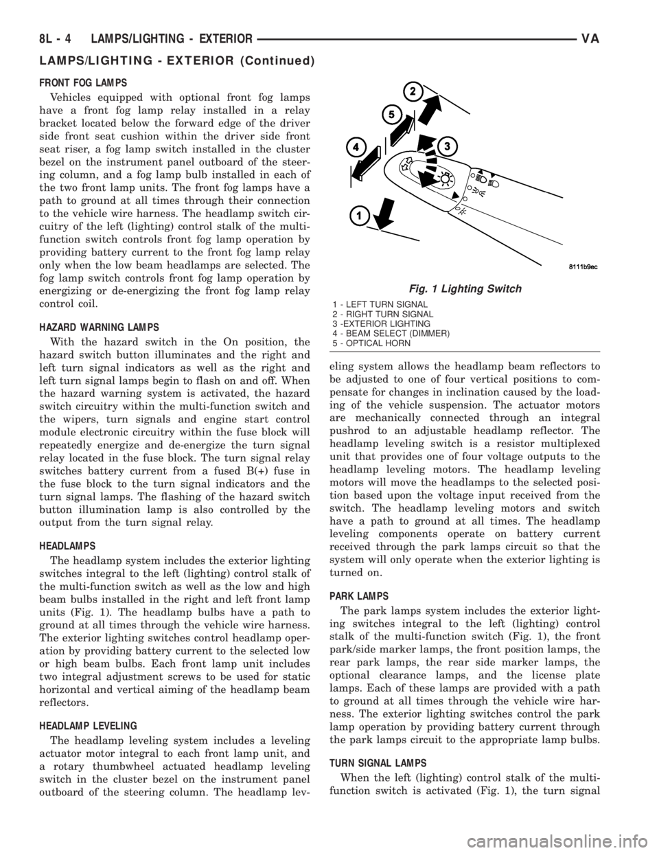
HEADLAMPS
The headlamp system includes the exterior lighting
switches integral to the left (lighting) control stalk of
the multi-function switch as well as the low and high
beam bulbs installed in the right and left front lamp
units (Fig. 1). The headlamp bulbs have a path to
ground at all times through the vehicle wire harness.
The exterior lighting switches control headlamp oper-
ation by providing battery current to the selected low
or high beam bulbs. Each front lamp unit includes
two integral adjustment screws to be used for static
horizontal and vertical aiming of the headlamp beam
reflectors.
HEADLAMP LEVELING
The headlamp leveling system includes a leveling
actuator motor integral to each front lamp unit, and
a rotary thumbwheel actuated headlamp leveling
switch in the cluster bezel on the instrument panel
outboard of the steering column. The headlamp lev-eling system allows the headlamp beam reflectors to
be adjusted to one of four vertical positions to com-
pensate for changes in inclination caused by the load-
ing of the vehicle suspension. The actuator motors
are mechanically connected through an integral
pushrod to an adjustable headlamp reflector. The
headlamp leveling switch is a resistor multiplexed
unit that provides one of four voltage outputs to the
headlamp leveling motors. The headlamp leveling
motors will move the headlamps to the selected posi-
tion based upon the voltage input received from the
switch. The headlamp leveling motors and switch
have a path to ground at all times. The headlamp
leveling components operate on battery current
received through the park lamps circuit so that the
system will only operate when the exterior lighting is
turned on.
PARK LAMPS
The park lamps system includes the exterior light-
ing switches integral to the left (lighting) control
stalk of the multi-function switch (Fig. 1), the front
park/side marker lamps, the front position lamps, the
rear park lamps, the rear side marker lamps, the
optional clearance lamps, and the license plate
lamps. Each of these lamps are provided with a path
to ground at all times through the vehicle wire har-
ness. The exterior lighting switches control the park
lamp operation by providing battery current through
the park lamps circuit to the appropriate lamp bulbs.
TURN SIGNAL LAMPS
When the left (lighting) control stalk of the multi-
function switch is activated (Fig. 1), the turn signal
Fig. 1 Lighting Switch
1 - LEFT TURN SIGNAL
2 - RIGHT TURN SIGNAL
3 -EXTERIOR LIGHTING
4 - BEAM SELECT (DIMMER)
5 - OPTICAL HORN
8L - 4 LAMPS/LIGHTING - EXTERIORVA
LAMPS/LIGHTING - EXTERIOR (Continued)