2005 MERCEDES-BENZ SPRINTER change wheel
[x] Cancel search: change wheelPage 243 of 1232
WARNING
WARNINGS - RESTRAINT SYSTEM
WARNING: DURING AND FOLLOWING ANY SEAT
BELT SERVICE, CAREFULLY INSPECT ALL SEAT
BELTS, BUCKLES, MOUNTING HARDWARE,
RETRACTORS, TETHER STRAPS, AND ANCHORS
FOR PROPER INSTALLATION, OPERATION, OR
DAMAGE. REPLACE ANY BELT THAT IS CUT,
FRAYED, OR TORN. STRAIGHTEN ANY BELT THAT
IS TWISTED. TIGHTEN ANY LOOSE FASTENERS.
REPLACE ANY BELT THAT HAS A DAMAGED OR
INOPERATIVE BUCKLE OR RETRACTOR. REPLACE
ANY BELT THAT HAS A BENT OR DAMAGED
LATCH PLATE OR ANCHOR PLATE. NEVER
ATTEMPT TO REPAIR A SEAT BELT COMPONENT.
ALWAYS REPLACE DAMAGED OR FAULTY SEAT
BELT COMPONENTS WITH THE CORRECT, NEW
AND UNUSED REPLACEMENT PARTS LISTED IN
THE DAIMLERCHRYSLER MOPAR PARTS CATA-
LOG.
WARNING: ON VEHICLES EQUIPPED WITH AIR-
BAGS, DISABLE THE SUPPLEMENTAL RESTRAINT
SYSTEM BEFORE ATTEMPTING ANY STEERING
WHEEL, STEERING COLUMN, DRIVER AIRBAG,
PASSENGER AIRBAG, SEAT BELT TENSIONER, OR
INSTRUMENT PANEL COMPONENT DIAGNOSIS OR
SERVICE. DISCONNECT AND ISOLATE THE BAT-
TERY NEGATIVE (GROUND) CABLE, THEN WAIT
TWO MINUTES FOR THE SYSTEM CAPACITOR TO
DISCHARGE BEFORE PERFORMING FURTHER
DIAGNOSIS OR SERVICE. THIS IS THE ONLY SURE
WAY TO DISABLE THE SUPPLEMENTAL
RESTRAINT SYSTEM. FAILURE TO TAKE THE
PROPER PRECAUTIONS COULD RESULT IN ACCI-
DENTAL AIRBAG DEPLOYMENT AND POSSIBLE
PERSONAL INJURY.
WARNING: ON VEHICLES EQUIPPED WITH AIR-
BAGS, BEFORE PERFORMING ANY WELDING
OPERATIONS DISCONNECT AND ISOLATE THE
BATTERY NEGATIVE (GROUND) CABLE AND DIS-
CONNECT ALL WIRE HARNESS CONNECTORS
FROM THE AIRBAG CONTROL MODULE (ACM).
FAILURE TO TAKE THE PROPER PRECAUTIONS
COULD RESULT IN ACCIDENTAL AIRBAG DEPLOY-
MENT AND OTHER POSSIBLE DAMAGE TO THE
SUPPLEMENTAL RESTRAINT SYSTEM CIRCUITS
AND COMPONENTS.
WARNING: AN AIRBAG INFLATOR UNIT MAY CON-
TAIN SODIUM AZIDE AND POTASSIUM NITRATE.THESE MATERIALS ARE POISONOUS AND
EXTREMELY FLAMMABLE. CONTACT WITH ACID,
WATER, OR HEAVY METALS MAY PRODUCE HARM-
FUL AND IRRITATING GASES (SODIUM HYDROXIDE
IS FORMED IN THE PRESENCE OF MOISTURE) OR
COMBUSTIBLE COMPOUNDS. AN AIRBAG INFLA-
TOR UNIT MAY ALSO CONTAIN A GAS CANISTER
PRESSURIZED TO OVER 2500 PSI. DO NOT
ATTEMPT TO DISMANTLE AN AIRBAG UNIT OR
TAMPER WITH ITS INFLATOR. DO NOT PUNCTURE,
INCINERATE, OR BRING INTO CONTACT WITH
ELECTRICITY. DO NOT STORE AT TEMPERATURES
EXCEEDING 93É C (200É F).
WARNING: WHEN HANDLING A SEAT BELT TEN-
SIONER RETRACTOR, PROPER CARE SHOULD BE
EXERCISED TO KEEP FINGERS OUT FROM UNDER
THE RETRACTOR COVER AND AWAY FROM THE
SEAT BELT WEBBING WHERE IT EXITS FROM THE
RETRACTOR COVER.
WARNING: REPLACE ALL RESTRAINT SYSTEM
COMPONENTS ONLY WITH PARTS SPECIFIED IN
THE DAIMLERCHRYSLER MOPAR PARTS CATA-
LOG. SUBSTITUTE PARTS MAY APPEAR INTER-
CHANGEABLE, BUT INTERNAL DIFFERENCES MAY
RESULT IN INFERIOR OCCUPANT PROTECTION.
WARNING: THE FASTENERS, SCREWS, AND
BOLTS ORIGINALLY USED FOR THE RESTRAINT
SYSTEM COMPONENTS HAVE SPECIAL COATINGS
AND ARE SPECIFICALLY DESIGNED FOR THE
RESTRAINT SYSTEM. THEY MUST NEVER BE
REPLACED WITH ANY SUBSTITUTES. ANY TIME A
NEW FASTENER IS NEEDED, REPLACE IT WITH
THE CORRECT FASTENERS PROVIDED IN THE
SERVICE PACKAGE OR SPECIFIED IN THE
DAIMLERCHRYSLER MOPAR PARTS CATALOG.
WARNING: WHEN A STEERING COLUMN HAS AN
AIRBAG UNIT ATTACHED, NEVER PLACE THE COL-
UMN ON THE FLOOR OR ANY OTHER SURFACE
WITH THE STEERING WHEEL OR AIRBAG UNIT
FACE DOWN.
DIAGNOSIS AND TESTING - SUPPLEMENTAL
RESTRAINT SYSTEM
Proper diagnosis and testing of the supplemental
restraint system components or the Airbag Control
Module (ACM), initialization of the ACM, as well as
the retrieval or erasure of a Diagnostic Trouble Code
(DTC) from the ACM requires the use of a DRBIIIt
scan tool. Refer to the appropriate diagnostic infor-
mation.
VARESTRAINTS 8O - 5
RESTRAINTS (Continued)
Page 251 of 1232
vide access to the case mounting screws. The lower
side of the rotor hub also serves as an integral
molded plastic turn signal cancel cam.
A single connector receptacle on the upper surface
of the rotor has pigtail wires that connect to the horn
switch and the driver airbag on the steering wheel,
while a single connector receptacle on the lower sur-
face of the case has pigtail wires that connect the
clockspring to the vehicle wire harness on the steer-
ing column. Within the plastic case and wound
around the rotor spool is a long ribbon-like tape that
consists of several thin copper wire leads sandwiched
between two thin plastic membranes. The outer end
of the tape terminates at the connector receptacle
that faces the steering column, while the inner end of
the tape terminates at the connector receptacle on
the hub of the clockspring rotor that faces the steer-
ing wheel.
Service replacement clocksprings are shipped pre-
centered and with the mounting screws backed out
from the case far enough to engage the access holes
in the upper surface of the rotor. The mounting
screws secure the centered clockspring rotor to the
clockspring case during shipment, but allow free
rotation of the rotor once the clockspring is properly
installed on the steering column. (Refer to 8 - ELEC-
TRICAL/RESTRAINTS/CLOCKSPRING - STAN-
DARD PROCEDURE - CLOCKSPRING
CENTERING).
The clockspring cannot be repaired. If the clock-
spring is faulty, damaged, or if the driver airbag has
been deployed, the clockspring must be replaced.
OPERATION
The clockspring is a mechanical electrical circuit
component that is used to provide continuous electri-
cal continuity between the fixed vehicle wire harness
and the electrical components mounted on or in the
rotating steering wheel. On this model the rotating
electrical components include the driver airbag and
the horn switch. The clockspring case is positioned
and secured to the multi-function switch housing
near the top of the steering column. The connector
receptacle on the underside of the fixed clockspring
case connects the clockspring to the vehicle electrical
system through two take outs with connectors from
the vehicle wire harness.
The clockspring rotor is movable and is keyed by
integral molded ribs on the inner circumference of
the rotor hub to the splines on the external circum-
ference of the upper steering column shaft. The two
integral lobes of the turn signal cancel cam formation
on the lower surface of the clockspring rotor hub con-
tact the turn signal cancel actuator of the multi-func-
tion switch to provide automatic turn signal
cancellation. The yellow sleeved pigtail wire on theupper surface of the clockspring rotor connects the
clockspring to the driver airbag, while two single pig-
tail wires connect to the feed and ground terminals of
the horn switch located within the hub cavity of the
steering wheel.
Like the clockspring in a timepiece, the clockspring
tape has travel limits and can be damaged by being
wound too tightly during full stop-to-stop steering
wheel rotation. To prevent this from occurring, the
clockspring is centered when it is installed on the
steering column. Centering the clockspring indexes
the clockspring tape to the movable steering compo-
nents so that the tape can operate within its
designed travel limits. However, if the clockspring is
removed from the steering column or if the steering
shaft is disconnected from the steering gear, the
clockspring spool can change position relative to the
movable steering components. The clockspring must
be re-centered following completion of this service or
the tape may be damaged.
Service replacement clocksprings are shipped pre-
centered and with the mounting screws backed out
from the case far enough to engage the access holes
in the upper surface of the rotor. The mounting
screws secure the centered clockspring rotor to the
clockspring case during shipment, but allow free
rotation of the rotor once the clockspring is properly
installed on the steering column. The clockspring
mounting screws should not be tightened into the
clockspring case until the clockspring has been
installed on the steering column. If the screws are
tightened into or removed from the case before the
clockspring is installed on a steering column, the
clockspring centering procedure must be performed.
(Refer to 8 - ELECTRICAL/RESTRAINTS/CLOCK-
SPRING - STANDARD PROCEDURE - CLOCK-
SPRING CENTERING).
STANDARD PROCEDURE - CLOCKSPRING
CENTERING
The clockspring is designed to wind and unwind
when the steering wheel is rotated, but is only
designed to rotate the same number of turns (about
six to seven complete rotations) as the steering wheel
can be turned from stop to stop. Centering the clock-
spring indexes the clockspring tape to other steering
components so that it can operate within its designed
travel limits. The rotor of a centered clockspring can
be rotated three to three and one-half turns in either
direction from the centered position, without damag-
ing the clockspring tape.
However, if the clockspring is removed for service
or if the steering column is disconnected from the
steering gear, the clockspring tape can change posi-
tion relative to the other steering components. The
clockspring must then be re-centered following com-
VARESTRAINTS 8O - 13
CLOCKSPRING (Continued)
Page 257 of 1232
WARNING: USE EXTREME CARE TO PREVENT ANY
FOREIGN MATERIAL FROM ENTERING THE DRIVER
AIRBAG, OR BECOMING ENTRAPPED BETWEEN
THE DRIVER AIRBAG CUSHION AND THE DRIVER
AIRBAG TRIM COVER. FAILURE TO OBSERVE THIS
WARNING COULD RESULT IN OCCUPANT INJURIES
UPON AIRBAG DEPLOYMENT.
WARNING: THE DRIVER AIRBAG TRIM COVER
MUST NEVER BE PAINTED. REPLACEMENT AIR-
BAGS ARE SERVICED WITH TRIM COVERS IN THE
ORIGINAL COLORS. PAINT MAY CHANGE THE WAY
IN WHICH THE MATERIAL OF THE TRIM COVER
RESPONDS TO AN AIRBAG DEPLOYMENT. FAIL-
URE TO OBSERVE THIS WARNING COULD RESULT
IN OCCUPANT INJURIES UPON AIRBAG DEPLOY-
MENT.
(1) Position the driver airbag close enough to the
steering wheel to reconnect the clockspring driver
airbag pigtail wire connector at the back of the air-
bag housing.
(2) When installing the driver airbag, reconnect
the clockspring driver airbag pigtail wire connector
to the airbag inflator connector receptacle by press-
ing straight in on the connector (Fig. 21). You can be
certain that the connector is fully engaged by listen-
ing carefully for a distinct, audible click as the con-
nector snaps into place.
(3) Carefully position the driver airbag in the
steering wheel. Be certain that the clockspring pig-
tail wire and horn switch wires in the steering wheel
hub area are not pinched between the driver airbag
and the horn switch armature.
(4) From the underside of the steering wheel,
install and tighten the two screws that secure the
driver airbag to the horn switch armature within the
hub cavity of the steering wheel. Tighten the screws
to 6 N´m (53 in. lbs.).
(5) Do not reconnect the battery negative cable at
this time. The supplemental restraint system verifi-
cation test procedure should be performed following
service of any supplemental restraint system compo-
nent. (Refer to 8 - ELECTRICAL/RESTRAINTS -
STANDARD PROCEDURE - VERIFICATION TEST).
FRONT SEAT BELT &
RETRACTOR
REMOVAL
The following procedure is for replacement of a
faulty or damaged front seat belt and retractor unit,
which includes a seat belt tensioner for the driver
side as standard equipment. Vehicles equipped withan optional passenger airbag also have a seat belt
tensioner for the passenger side. (Refer to 8 - ELEC-
TRICAL/RESTRAINTS/SEAT BELT TENSIONER -
DESCRIPTION). If the seat belt or retractor is faulty
or damaged, but the seat belt tensioner is not
deployed, review the recommended procedures for
handling non-deployed supplemental restraints.
(Refer to 8 - ELECTRICAL/RESTRAINTS - STAN-
DARD PROCEDURE - HANDLING NON-DE-
PLOYED SUPPLEMENTAL RESTRAINTS). If the
seat belt tensioner has been deployed, review the rec-
ommended procedures for service after a supplemen-
tal restraint deployment before removing the front
seat belt and retractor from the vehicle. (Refer to 8 -
ELECTRICAL/RESTRAINTS - STANDARD PROCE-
DURE - SERVICE AFTER A SUPPLEMENTAL
RESTRAINT DEPLOYMENT).
WARNING: ON VEHICLES EQUIPPED WITH AIR-
BAGS, DISABLE THE SUPPLEMENTAL RESTRAINT
SYSTEM BEFORE ATTEMPTING ANY STEERING
WHEEL, STEERING COLUMN, DRIVER AIRBAG,
PASSENGER AIRBAG, SEAT BELT TENSIONER, OR
INSTRUMENT PANEL COMPONENT DIAGNOSIS OR
SERVICE. DISCONNECT AND ISOLATE THE BAT-
TERY NEGATIVE (GROUND) CABLE, THEN WAIT
TWO MINUTES FOR THE SYSTEM CAPACITOR TO
DISCHARGE BEFORE PERFORMING FURTHER
DIAGNOSIS OR SERVICE. THIS IS THE ONLY SURE
WAY TO DISABLE THE SUPPLEMENTAL
RESTRAINT SYSTEM. FAILURE TO TAKE THE
PROPER PRECAUTIONS COULD RESULT IN ACCI-
DENTAL AIRBAG DEPLOYMENT AND POSSIBLE
PERSONAL INJURY.
WARNING: DURING AND FOLLOWING ANY SEAT
BELT SERVICE, CAREFULLY INSPECT ALL SEAT
BELTS, BUCKLES, MOUNTING HARDWARE,
RETRACTORS, AND ANCHORS FOR PROPER
INSTALLATION, OPERATION, OR DAMAGE.
REPLACE ANY BELT THAT IS CUT, FRAYED, OR
TORN. STRAIGHTEN ANY BELT THAT IS TWISTED.
TIGHTEN ANY LOOSE FASTENERS. REPLACE ANY
BELT THAT HAS A DAMAGED OR INOPERATIVE
BUCKLE OR RETRACTOR. REPLACE ANY BELT
THAT HAS A BENT OR DAMAGED LATCH PLATE
OR ANCHOR PLATE. NEVER ATTEMPT TO REPAIR
A SEAT BELT COMPONENT. ALWAYS REPLACE
DAMAGED OR FAULTY SEAT BELT COMPONENTS
WITH THE CORRECT, NEW AND UNUSED
REPLACEMENT PARTS LISTED IN THE
DAIMLERCHRYSLER MOPAR PARTS CATALOG.
(1) Move the front seat to its most forward position
for easiest access to the B-pillar trim.
VARESTRAINTS 8O - 19
DRIVER AIRBAG (Continued)
Page 264 of 1232
INSTALLATION
The following procedure is for replacement of a
faulty or damaged passenger airbag. If the airbag is
faulty or damaged, but not deployed, review the rec-
ommended procedures for handling non-deployed
supplemental restraints. (Refer to 8 - ELECTRICAL/
RESTRAINTS - STANDARD PROCEDURE - HAN-
DLING NON-DEPLOYED SUPPLEMENTAL
RESTRAINTS). If the passenger airbag has been
deployed, review the recommended procedures for
service after a supplemental restraint deployment
before removing the airbag from the vehicle. (Refer to
8 - ELECTRICAL/RESTRAINTS - STANDARD PRO-
CEDURE - SERVICE AFTER A SUPPLEMENTAL
RESTRAINT DEPLOYMENT).
WARNING: ON VEHICLES EQUIPPED WITH AIR-
BAGS, DISABLE THE SUPPLEMENTAL RESTRAINT
SYSTEM BEFORE ATTEMPTING ANY STEERING
WHEEL, STEERING COLUMN, DRIVER AIRBAG,
PASSENGER AIRBAG, SEAT BELT TENSIONER, OR
INSTRUMENT PANEL COMPONENT DIAGNOSIS OR
SERVICE. DISCONNECT AND ISOLATE THE BAT-
TERY NEGATIVE (GROUND) CABLE, THEN WAIT
TWO MINUTES FOR THE SYSTEM CAPACITOR TO
DISCHARGE BEFORE PERFORMING FURTHER
DIAGNOSIS OR SERVICE. THIS IS THE ONLY SURE
WAY TO DISABLE THE SUPPLEMENTAL
RESTRAINT SYSTEM. FAILURE TO TAKE THE
PROPER PRECAUTIONS COULD RESULT IN ACCI-
DENTAL AIRBAG DEPLOYMENT AND POSSIBLE
PERSONAL INJURY.
WARNING: WHEN REMOVING A DEPLOYED AIR-
BAG, RUBBER GLOVES, EYE PROTECTION, AND A
LONG-SLEEVED SHIRT SHOULD BE WORN. THERE
MAY BE DEPOSITS ON THE AIRBAG UNIT AND
OTHER INTERIOR SURFACES. IN LARGE DOSES,
THESE DEPOSITS MAY CAUSE IRRITATION TO THE
SKIN AND EYES.
WARNING: USE EXTREME CARE TO PREVENT ANY
FOREIGN MATERIAL FROM ENTERING THE PAS-
SENGER AIRBAG, OR BECOMING ENTRAPPED
BETWEEN THE PASSENGER AIRBAG CUSHION
AND THE PASSENGER AIRBAG DOOR. FAILURE TO
OBSERVE THIS WARNING COULD RESULT IN
OCCUPANT INJURIES UPON AIRBAG DEPLOY-
MENT.WARNING: THE PASSENGER AIRBAG DOOR MUST
NEVER BE PAINTED. REPLACEMENT PASSENGER
AIRBAGS ARE SERVICED WITH DOORS IN THE
ORIGINAL COLORS. PAINT MAY CHANGE THE WAY
IN WHICH THE MATERIAL OF THE AIRBAG DOOR
RESPONDS TO AN AIRBAG DEPLOYMENT. FAIL-
URE TO OBSERVE THIS WARNING COULD RESULT
IN OCCUPANT INJURIES UPON AIRBAG DEPLOY-
MENT.
(1) Carefully position the passenger airbag and
airbag door unit to the instrument panel (Fig. 29).
(2) When installing the passenger airbag, recon-
nect the vehicle wire harness connector to the airbag
inflator connector receptacle by pressing straight in
on the connector. You can be certain that the connec-
tor is fully engaged by listening carefully for a dis-
tinct, audible click as the connector snaps into place.
(3) Push the passenger airbag unit forward far
enough to engage the lower edge of the airbag door
with the two lower clips in the instrument panel.
(4) Install and tighten the two screws that secure
the flange of the passenger airbag housing to the
bracket on the instrument panel structural support.
Tighten the screws to 10 N´m (89 in. lbs.).
(5) Install and tighten the two screws that secure
the passenger airbag door upper clips to the instru-
ment panel base trim. Tighten the screws to 2 N´m
(18 in. lbs.).
(6) Reinstall the instrument panel top cover tray
onto the instrument panel. (Refer to 23 - BODY/IN-
STRUMENT PANEL/INSTRUMENT PANEL TOP
COVER - TRAY - INSTALLATION).
(7) Do not reconnect the battery negative cable at
this time. The supplemental restraint system verifi-
cation test procedure should be performed following
service of any supplemental restraint system compo-
nent. (Refer to 8 - ELECTRICAL/RESTRAINTS -
STANDARD PROCEDURE - VERIFICATION TEST).
8O - 26 RESTRAINTSVA
PASSENGER AIRBAG (Continued)
Page 286 of 1232
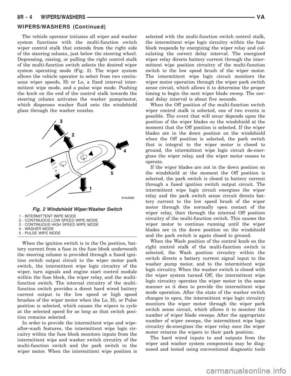
The vehicle operator initiates all wiper and washer
system functions with the multi-function switch
wiper control stalk that extends from the right side
of the steering column, just below the steering wheel.
Depressing, raising, or pulling the right control stalk
of the multi-function switch selects the desired wiper
system operating mode (Fig. 2). The wiper system
allows the vehicle operator to select from two contin-
uous wiper speeds, Hi or Lo, a fixed interval inter-
mittent wipe mode, and a pulse wipe mode. Pushing
the knob on the end of the control stalk towards the
steering column activates the washer pump/motor,
which dispenses washer fluid onto the windshield
glass through the washer nozzles.
When the ignition switch is in the On position, bat-
tery current from a fuse in the fuse block underneath
the steering column is provided through a fused igni-
tion switch output circuit to the wiper motor park
switch, the intermittent wipe logic circuitry of the
wiper, turn signals and engine start control module
within the fuse block, the wiper relay, and the multi-
function switch. The internal circuitry of the multi-
function switch provides a direct hard wired battery
current output to the low speed or high speed
brushes of the wiper motor when the Lo, Hi, or Pulse
position is selected, which causes the wipers to cycle
at the selected speed for as long as that switch posi-
tion remains selected.
In order to provide the intermittent wipe and wipe-
after-wash features, the intermittent wipe logic cir-
cuitry within the fuse block monitors inputs from the
intermittent wipe and washer switch circuitry of the
multi-function switch and the park switch in the
wiper motor. When the intermittent wipe position isselected with the multi-function switch control stalk,
the intermittent wipe logic circuitry within the fuse
block responds by energizing the wiper relay and cal-
culating the correct delay interval. The energized
wiper relay directs battery current through the inter-
mittent wipe position circuitry of the multi-function
switch to the low speed brush of the wiper motor.
The intermittent wipe logic circuit monitors the
wiper motor operation through the wiper park switch
sense circuit, which allows it to determine the proper
timing to begin the next wiper blade sweep. The nor-
mal delay interval is about five seconds.
When the Off position of the multi-function switch
wiper control stalk is selected, one of two events is
possible. The event that will occur depends upon the
position of the wiper blades on the windshield at the
moment that the Off position is selected. If the wiper
blades are in the down position on the windshield
when the Off position is selected, the park switch
that is integral to the wiper motor is closed to
ground, the intermittent wipe logic circuit de-ener-
gizes the wiper relay, and the wiper motor ceases to
operate.
If the wiper blades are not in the down position on
the windshield at the moment the Off position is
selected, the park switch is closed to battery current
through a fused ignition switch output circuit. The
intermittent wipe logic circuit energizes the wiper
relay and the park switch sense circuit directs bat-
tery current to the low speed brush of the wiper
motor through the normally open contact of the
wiper relay, then through the internal Off position
circuitry of the multi-function switch. This causes the
wiper motor to continue running until the wiper
blades are in the down position on the windshield
and the park switch is again closed to ground.
When the Wash position of the control knob on the
right control stalk of the multi-function switch is
selected, the Wash position circuitry within the
switch directs a battery current signal input to the
washer pump motor, and to the intermittent wipe
logic circuitry. When the washer switch is closed with
the wiper system turned Off, the intermittent wipe
logic circuitry operates the wiper motor in the same
manner as it does to provide the intermittent wipe
mode operation. After the state of the washer switch
changes to open, the intermittent wipe logic circuitry
monitors the wiper motor through the wiper park
switch sense circuit, which allows it to monitor the
number of wiper blade sweeps. After the appropriate
number of wiper sweeps, the intermittent wipe logic
circuitry de-energizes the wiper relay once the wiper
motor returns the wipers to their park position.
The hard wired inputs to and outputs from the
wiper and washer system components may be diag-
nosed and tested using conventional diagnostic tools
Fig. 2 Windshield Wiper/Washer Switch
1 - INTERMITTENT WIPE MODE
2 - CONTINUOUS LOW SPEED WIPE MODE
3 - CONTINUOUS HIGH SPEED WIPE MODE
4 - WASHER MODE
5 - PULSE WIPE MODE
8R - 4 WIPERS/WASHERSVA
WIPERS/WASHERS (Continued)
Page 777 of 1232
FLYWHEEL
REMOVAL
(1) Remove transmission (Refer to 21 - TRANS-
MISSION/TRANSAXLE/AUTOMATIC - W5J400 -
REMOVAL).
NOTE: M6x90 bolts must be used with retaining
lock to prevent damage to rear end cover.
(2) Install retaining lock for crankshaft/starter
ring gear.
NOTE: Flywheel does not need balancing or should
it be interchanged.
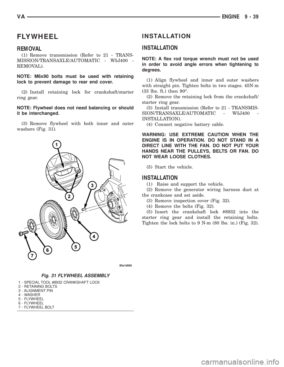
(3) Remove flywheel with both inner and outer
washers (Fig. 31).
INSTALLATION
INSTALLATION
NOTE: A flex rod torque wrench must not be used
in order to avoid angle errors when tightening to
degrees.
(1) Align flywheel and inner and outer washers
with straight pin. Tighten bolts in two stages. 45N´m
(33 lbs. ft.) then 90É.
(2) Remove the retaining lock from the crankshaft/
starter ring gear.
(3) Install transmission (Refer to 21 - TRANSMIS-
SION/TRANSAXLE/AUTOMATIC - W5J400 -
INSTALLATION).
(4) Connect negative battery cable.
WARNING: USE EXTREME CAUTION WHEN THE
ENGINE IS IN OPERATION. DO NOT STAND IN A
DIRECT LINE WITH THE FAN. DO NOT PUT YOUR
HANDS NEAR THE PULLEYS, BELTS OR FAN. DO
NOT WEAR LOOSE CLOTHES.
(5) Start the vehicle.
INSTALLATION
(1) Raise and support the vehicle.
(2) Remove the generator wiring harness duct at
the crankcase and set aside.
(3) Remove inspection cover (Fig. 32).
(4) Remove the bolts (Fig. 32).
(5) Insert the crankshaft lock #8932 into the
starter ring gear and install the retaining bolts.
Tighten the lock bolts to 9 N´m (80 lbs. in.) (Fig. 32).
Fig. 31 FLYWHEEL ASSEMBLY
1 - SPECIAL TOOL #8932 CRANKSHAFT LOCK
2 - RETAINING BOLTS
3 - ALIGNMENT PIN
4 - WASHER
5 - FLYWHEEL
6 - FLYWHEEL
7 - FLYWHEEL BOLT
VAENGINE 9 - 39
Page 814 of 1232
²Higher torque as a result of improved cylinder
charge.
²Reduction in exhaust emissions as a result of an
improvement in the air supply of the engine.
²Increased power output as a result of the higher
charge pressure combined with a reduced exhaust
backpressure and thus improved charge cycle.
OPERATION
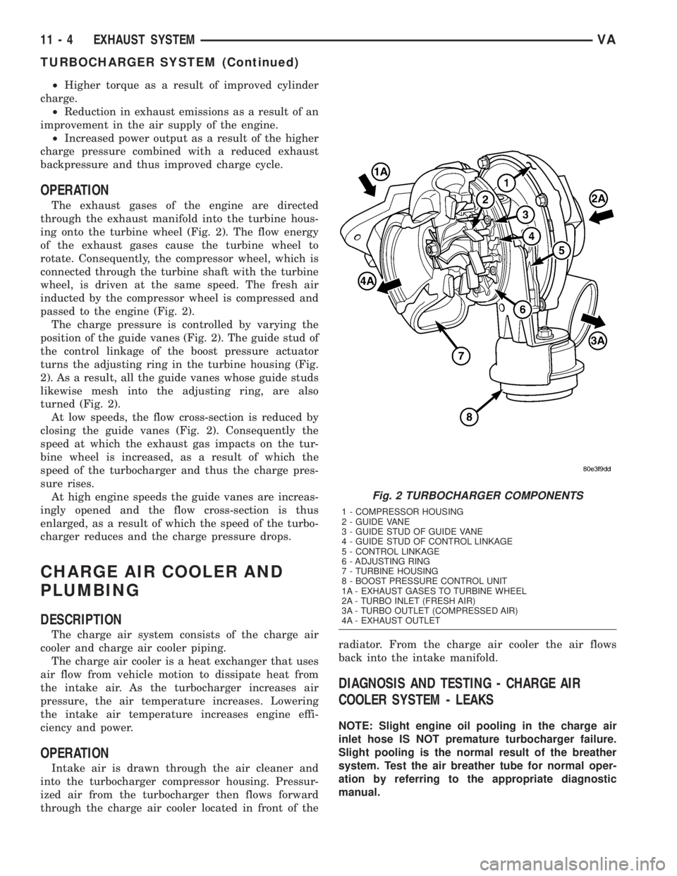
The exhaust gases of the engine are directed
through the exhaust manifold into the turbine hous-
ing onto the turbine wheel (Fig. 2). The flow energy
of the exhaust gases cause the turbine wheel to
rotate. Consequently, the compressor wheel, which is
connected through the turbine shaft with the turbine
wheel, is driven at the same speed. The fresh air
inducted by the compressor wheel is compressed and
passed to the engine (Fig. 2).
The charge pressure is controlled by varying the
position of the guide vanes (Fig. 2). The guide stud of
the control linkage of the boost pressure actuator
turns the adjusting ring in the turbine housing (Fig.
2). As a result, all the guide vanes whose guide studs
likewise mesh into the adjusting ring, are also
turned (Fig. 2).
At low speeds, the flow cross-section is reduced by
closing the guide vanes (Fig. 2). Consequently the
speed at which the exhaust gas impacts on the tur-
bine wheel is increased, as a result of which the
speed of the turbocharger and thus the charge pres-
sure rises.
At high engine speeds the guide vanes are increas-
ingly opened and the flow cross-section is thus
enlarged, as a result of which the speed of the turbo-
charger reduces and the charge pressure drops.
CHARGE AIR COOLER AND
PLUMBING
DESCRIPTION
The charge air system consists of the charge air
cooler and charge air cooler piping.
The charge air cooler is a heat exchanger that uses
air flow from vehicle motion to dissipate heat from
the intake air. As the turbocharger increases air
pressure, the air temperature increases. Lowering
the intake air temperature increases engine effi-
ciency and power.
OPERATION
Intake air is drawn through the air cleaner and
into the turbocharger compressor housing. Pressur-
ized air from the turbocharger then flows forward
through the charge air cooler located in front of theradiator. From the charge air cooler the air flows
back into the intake manifold.
DIAGNOSIS AND TESTING - CHARGE AIR
COOLER SYSTEM - LEAKS
NOTE: Slight engine oil pooling in the charge air
inlet hose IS NOT premature turbocharger failure.
Slight pooling is the normal result of the breather
system. Test the air breather tube for normal oper-
ation by referring to the appropriate diagnostic
manual.
Fig. 2 TURBOCHARGER COMPONENTS
1 - COMPRESSOR HOUSING
2 - GUIDE VANE
3 - GUIDE STUD OF GUIDE VANE
4 - GUIDE STUD OF CONTROL LINKAGE
5 - CONTROL LINKAGE
6 - ADJUSTING RING
7 - TURBINE HOUSING
8 - BOOST PRESSURE CONTROL UNIT
1A - EXHAUST GASES TO TURBINE WHEEL
2A - TURBO INLET (FRESH AIR)
3A - TURBO OUTLET (COMPRESSED AIR)
4A - EXHAUST OUTLET
11 - 4 EXHAUST SYSTEMVA
TURBOCHARGER SYSTEM (Continued)
Page 861 of 1232
STEERING
TABLE OF CONTENTS
page page
STEERING
DESCRIPTION..........................1
OPERATION............................1
DIAGNOSIS AND TESTING - POWER
STEERING SYSTEM....................2COLUMN...............................5
GEAR..................................8
LINKAGE..............................10
PUMP.................................12
STEERING
DESCRIPTION
CAUTION: Mopar ATF+4 Automatic Transmission
fluid or equivalent is to be used in the power steer-
ing system. No other power steering or automatic
transmission fluid is to be used in the system.
Damage may result to the power steering pump and
system if any other fluid is used, and do not over-
fill.
Power steering systems consist of:
²Steering column
²Rack and pinion steering gear
²Belt driven hydraulic steering pump
²Pump pressure and return hoses
²Oil Cooler
OPERATION
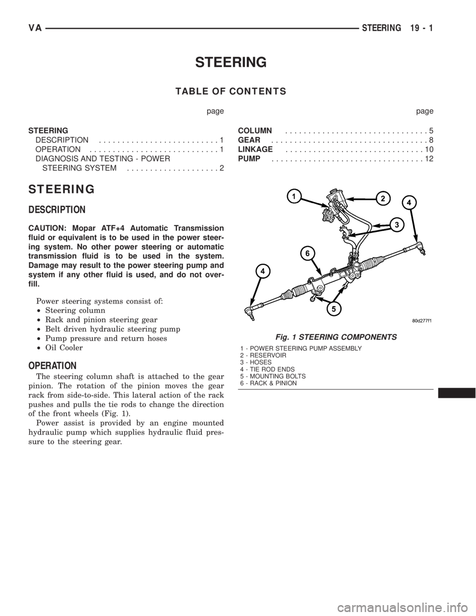
The steering column shaft is attached to the gear
pinion. The rotation of the pinion moves the gear
rack from side-to-side. This lateral action of the rack
pushes and pulls the tie rods to change the direction
of the front wheels (Fig. 1).
Power assist is provided by an engine mounted
hydraulic pump which supplies hydraulic fluid pres-
sure to the steering gear.
Fig. 1 STEERING COMPONENTS
1 - POWER STEERING PUMP ASSEMBLY
2 - RESERVOIR
3 - HOSES
4 - TIE ROD ENDS
5 - MOUNTING BOLTS
6 - RACK & PINION
VASTEERING 19 - 1