2005 MERCEDES-BENZ SPRINTER fuel type
[x] Cancel search: fuel typePage 11 of 1232
LUBRICATION & MAINTENANCE
TABLE OF CONTENTS
page page
FLUID TYPES
DESCRIPTION
DESCRIPTION - FUEL REQUIREMENTS -
DIESEL ENGINE.......................1
DESCRIPTION - ENGINE COOLANT........1
DESCRIPTION - HOAT COOLANT..........2
DESCRIPTION - AXLE...................3
DESCRIPTION - BRAKE FLUID............3
DESCRIPTION - POWER STEERING FLUID . . 3
DESCRIPTION - ENGINE OIL - DIESEL
ENGINES............................3
DESCRIPTION - AUTOMATIC
TRANSMISSION FLUID - NAG1............4
OPERATION - AUTOMATIC TRANSMISSION
FLUID...............................4
FLUID CAPACITIES
SPECIFICATIONS - FLUID CAPACITIES.......4FLUID FILL/CHECK LOCATIONS
INSPECTION - FLUID FILL/CHECK
LOCATIONS..........................4
PARTS & LUBRICANT RECOMMENDATION
STANDARD PROCEDURE - PARTS &
LUBRICANT RECOMMENDATIONS.........5
HOISTING
STANDARD PROCEDURE - HOISTING........5
JUMP STARTING
STANDARD PROCEDURE - JUMP STARTING . . 6
TOWING
STANDARD PROCEDURE - TOWING.........6
MAINTENANCE SCHEDULES
DESCRIPTION..........................7
INTERNATIONAL SYMBOLS
DESCRIPTION..........................9
FLUID TYPES
DESCRIPTION
DESCRIPTION - FUEL REQUIREMENTS -
DIESEL ENGINE
DESCRIPTION
WARNING: Do not use alcohol or gasoline as a fuel
blending agent. They can be unstable under certain
conditions and hazardous or explosive when mixed
with diesel fuel.
Use good quality diesel fuel from a reputable sup-
plier in your Dodge truck. For most year-round ser-
vice, number 2 diesel fuel meeting ASTM
specification D-975 will provide good performance. If
the vehicle is exposed to extreme cold (below 0ÉF/-
18ÉC), or is required to operate at colder-than-normal
conditions for prolonged periods, use climatized No. 2
diesel fuel or dilute the No. 2 diesel fuel with 50%
No. 1 diesel fuel. This will provide better protection
from fuel gelling or wax-plugging of the fuel filters.
Diesel fuel is seldom completely free of water. To
prevent fuel system trouble, including fuel line freez-
ing in winter, drain the accumulated water from the
fuel/water separator using the fuel/water separator
drain provided. If you buy good-quality fuel and fol-low the cold-weather advice above, fuel conditioners
should not be required in your vehicle. If available in
your area, a high cetane ªpremiumº diesel fuel may
offer improved cold starting and warm-up perfor-
mance.
DESCRIPTION - ENGINE COOLANT
ETHYLENE-GLYCOL MIXTURES
CAUTION: Richer antifreeze mixtures cannot be
measured with normal field equipment and can
cause problems associated with 100 percent ethyl-
ene-glycol.
The required ethylene-glycol (antifreeze) and water
mixture depends upon the climate and vehicle oper-
ating conditions. The recommended mixture of 50/50
ethylene-glycol and water will provide protection
against freezing to -37É C (-34É F). The antifreeze
concentrationmust alwaysbe a minimum of 44 per-
cent, year-round in all climates.If percentage is
lower than 44 percent, engine parts may be
eroded by cavitation, and cooling system com-
ponents may be severely damaged by corrosion.
Maximum protection against freezing is provided
with a 68 percent antifreeze concentration, which
prevents freezing down to -67.7É C (-90É F). A higher
percentage will freeze at a warmer temperature.
Also, a higher percentage of antifreeze can cause the
VALUBRICATION & MAINTENANCE 0 - 1
Page 14 of 1232
Full synthetic oils, such as Mobilt1 0W-40, is
required if the ASSYST Oil Service Reminder is fol-
lowed. Use of a lower quality oil on this service
schedule may cause severe engine damage.
DESCRIPTION - AUTOMATIC TRANSMISSION
FLUID - NAG1
NOTE: Refer to Service Procedures in this group for
fluid level checking procedures.
Shellt3403 Automatic Transmission Fluid is the
recommended fluid for the NAG1 DaimlerChrysler
automatic transmission.
Dexron II fluid IS NOT recommended. Clutch
chatter can result from the use of improper
fluid.
MopartATF+4, Automatic Transmission Fluid, or
other fluids meeting MS-9602, may be used if Shellt
3403 Automatic Transmission Fluid is not available.
Shellt3403 Automatic Transmission Fluid when
new is red in color. The ATF is dyed red so it can be
identified from other fluids used in the vehicle such
as engine oil or antifreeze. The red color is not per-
manent and is not an indicator of fluid condition. As
the vehicle is driven, the ATF will begin to look
darker in color and may eventually become brown.
This is normal.
FLUID ADDITIVES
DaimlerChrysler strongly recommends against the
addition of any fluids to the transmission, other than
those automatic transmission fluids listed above.
Exceptions to this policy are the use of special dyes
to aid in detecting fluid leaks.
Various ªspecialº additives and supplements exist
that claim to improve shift feel and/or quality. These
additives and others also claim to improve converter
clutch operation and inhibit overheating, oxidation,
varnish, and sludge. These claims have not been sup-
ported to the satisfaction of DaimlerChrysler and
these additivesmust not be used.The use of trans-
mission ªsealersº should also be avoided, since they
may adversely affect the integrity of transmission
seals.
OPERATION - AUTOMATIC TRANSMISSION
FLUID
The automatic transmission fluid is selected based
upon several qualities. The fluid must provide a high
level of protection for the internal components by
providing a lubricating film between adjacent metal
components. The fluid must also be thermally stable
so that it can maintain a consistent viscosity through
a large temperature range. If the viscosity stays con-
stant through the temperature range of operation,transmission operation and shift feel will remain con-
sistent. Transmission fluid must also be a good con-
ductor of heat. The fluid must absorb heat from the
internal transmission components and transfer that
heat to the transmission case.
FLUID CAPACITIES
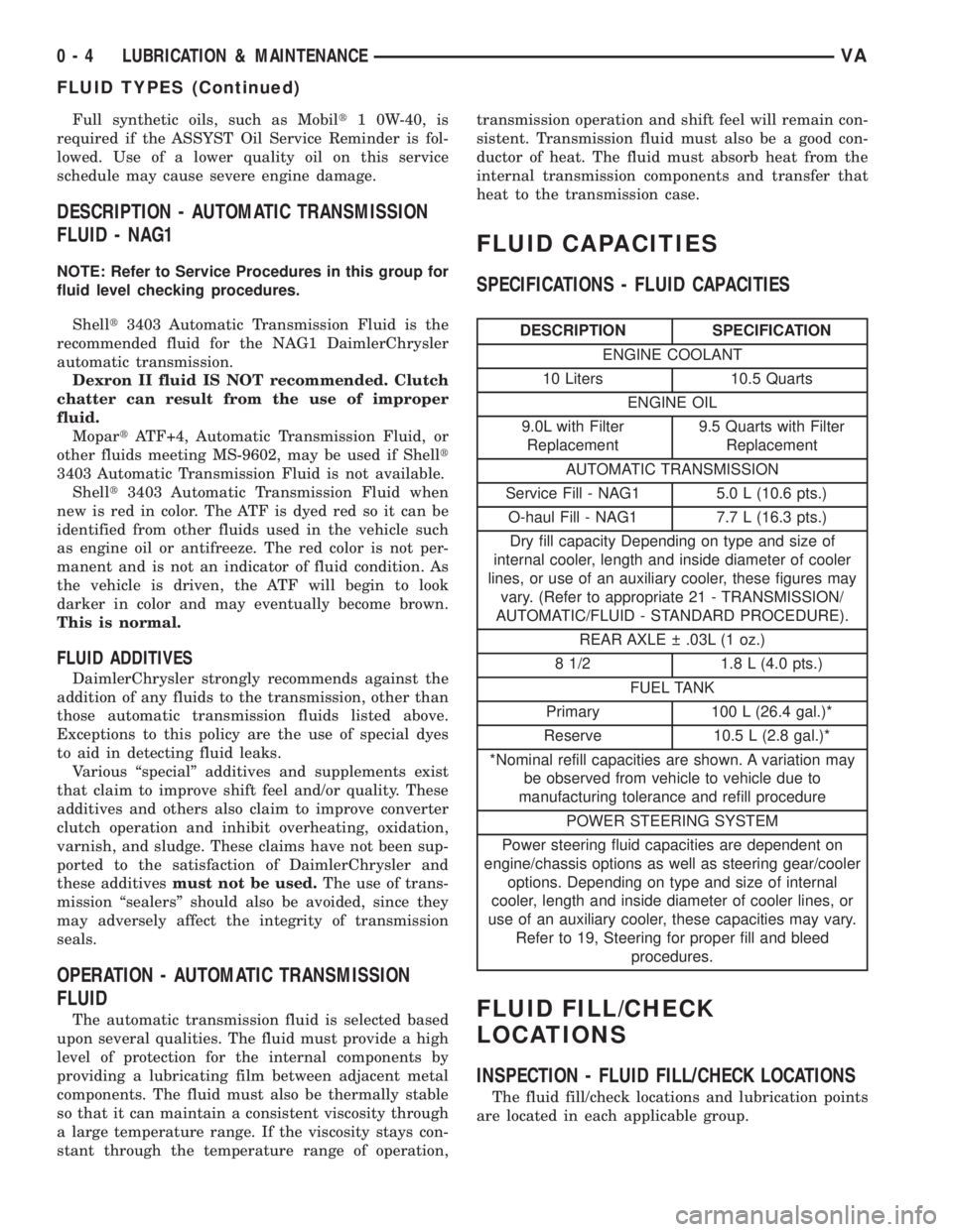
SPECIFICATIONS - FLUID CAPACITIES
DESCRIPTION SPECIFICATION
ENGINE COOLANT
10 Liters 10.5 Quarts
ENGINE OIL
9.0L with Filter
Replacement9.5 Quarts with Filter
Replacement
AUTOMATIC TRANSMISSION
Service Fill - NAG1 5.0 L (10.6 pts.)
O-haul Fill - NAG1 7.7 L (16.3 pts.)
Dry fill capacity Depending on type and size of
internal cooler, length and inside diameter of cooler
lines, or use of an auxiliary cooler, these figures may
vary. (Refer to appropriate 21 - TRANSMISSION/
AUTOMATIC/FLUID - STANDARD PROCEDURE).
REAR AXLE .03L (1 oz.)
8 1/2 1.8 L (4.0 pts.)
FUEL TANK
Primary 100 L (26.4 gal.)*
Reserve 10.5 L (2.8 gal.)*
*Nominal refill capacities are shown. A variation may
be observed from vehicle to vehicle due to
manufacturing tolerance and refill procedure
POWER STEERING SYSTEM
Power steering fluid capacities are dependent on
engine/chassis options as well as steering gear/cooler
options. Depending on type and size of internal
cooler, length and inside diameter of cooler lines, or
use of an auxiliary cooler, these capacities may vary.
Refer to 19, Steering for proper fill and bleed
procedures.
FLUID FILL/CHECK
LOCATIONS
INSPECTION - FLUID FILL/CHECK LOCATIONS
The fluid fill/check locations and lubrication points
are located in each applicable group.
0 - 4 LUBRICATION & MAINTENANCEVA
FLUID TYPES (Continued)
Page 15 of 1232
PARTS & LUBRICANT
RECOMMENDATION
STANDARD PROCEDURE - PARTS &
LUBRICANT RECOMMENDATIONS
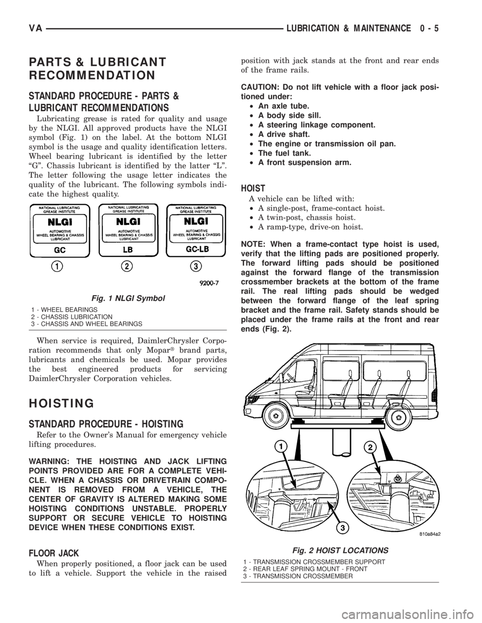
Lubricating grease is rated for quality and usage
by the NLGI. All approved products have the NLGI
symbol (Fig. 1) on the label. At the bottom NLGI
symbol is the usage and quality identification letters.
Wheel bearing lubricant is identified by the letter
ªGº. Chassis lubricant is identified by the latter ªLº.
The letter following the usage letter indicates the
quality of the lubricant. The following symbols indi-
cate the highest quality.
When service is required, DaimlerChrysler Corpo-
ration recommends that only Mopartbrand parts,
lubricants and chemicals be used. Mopar provides
the best engineered products for servicing
DaimlerChrysler Corporation vehicles.
HOISTING
STANDARD PROCEDURE - HOISTING
Refer to the Owner's Manual for emergency vehicle
lifting procedures.
WARNING: THE HOISTING AND JACK LIFTING
POINTS PROVIDED ARE FOR A COMPLETE VEHI-
CLE. WHEN A CHASSIS OR DRIVETRAIN COMPO-
NENT IS REMOVED FROM A VEHICLE, THE
CENTER OF GRAVITY IS ALTERED MAKING SOME
HOISTING CONDITIONS UNSTABLE. PROPERLY
SUPPORT OR SECURE VEHICLE TO HOISTING
DEVICE WHEN THESE CONDITIONS EXIST.
FLOOR JACK
When properly positioned, a floor jack can be used
to lift a vehicle. Support the vehicle in the raisedposition with jack stands at the front and rear ends
of the frame rails.
CAUTION: Do not lift vehicle with a floor jack posi-
tioned under:
²An axle tube.
²A body side sill.
²A steering linkage component.
²A drive shaft.
²The engine or transmission oil pan.
²The fuel tank.
²A front suspension arm.
HOIST
A vehicle can be lifted with:
²A single-post, frame-contact hoist.
²A twin-post, chassis hoist.
²A ramp-type, drive-on hoist.
NOTE: When a frame-contact type hoist is used,
verify that the lifting pads are positioned properly.
The forward lifting pads should be positioned
against the forward flange of the transmission
crossmember brackets at the bottom of the frame
rail. The real lifting pads should be wedged
between the forward flange of the leaf spring
bracket and the frame rail. Safety stands should be
placed under the frame rails at the front and rear
ends (Fig. 2).
Fig. 1 NLGI Symbol
1 - WHEEL BEARINGS
2 - CHASSIS LUBRICATION
3 - CHASSIS AND WHEEL BEARINGS
Fig. 2 HOIST LOCATIONS
1 - TRANSMISSION CROSSMEMBER SUPPORT
2 - REAR LEAF SPRING MOUNT - FRONT
3 - TRANSMISSION CROSSMEMBER
VALUBRICATION & MAINTENANCE 0 - 5
Page 17 of 1232
If the Engine is Damaged
For towing distances up to 30 miles (about 50
km)
²Shift selector lever in ªNº position.
²Do not exceed a towing speed of 30 m.p.h. (50
km/h).
For towing distances greater than 30 mile
(about 50 km)
²Remove the propeller shafts leading to the drive
axles. The vehicle can be towed without restriction.
If the Transmission is Damaged
²Remove the propeller shafts leading to the drive
axles. The vehicle can be towed without restriction.
If the Front Axle is Damaged
²Raise the front axle.
²Observe the same towing restrictions as for
engine damage.
If the Rear Axle is Damaged
²Raise the rear axle.
NOTE: Comply with local legal regulations regard-
ing towing vehicles.
SAFETY PRECAUTIONS
NOTE: The following safety precautions must be
observed when towing a vehicle.
²Secure loose and protruding parts.
²Always use a safety chain system that is inde-
pendent of the lifting and towing equipment.
²Do not allow towing equipment to contact the
disabled vehicle's fuel tank.
²Do not allow anyone under the disabled vehicle
while it is lifted by the towing device.
²Do not allow passengers to ride in a vehicle
being towed.
²Always observe state and local laws regarding
towing regulations.
²Do not tow a vehicle in a manner that could
jeopardize the safety of the operator, pedestrians or
other motorists.
²Do not attach tow chains, T-hooks, J-hooks, or a
tow sling to a bumper, steering linkage, drive shafts
or a non-reinforced frame hole.
²Remove exhaust pipe tips that interfere with the
tow sling and crossbar
²Padding should be placed between the tow sling/
crossbar and any painted surfaces
²When placing tow hooks on the rear axle, posi-
tion them so they do not damage the brake tubing or
hoses²Do not tow the vehicle by connecting to the front
or rear shock absorbers
²Do not tow a heavily loaded vehicle. Damage to
the vehicle may result. Use a flatbed device to trans-
port a loaded vehicle.
GROUND CLEARANCE
CAUTION: If vehicle is towed with wheels removed,
install lug nuts to retain brake drums.
A towed vehicle should be raised until lifted wheels
are a minimum 100 mm (4 in) from the ground. Be
sure there is adequate ground clearance at the oppo-
site end of the vehicle, especially when towing over
rough terrain, steep rises in the road or if the vehicle
is equipped with air dams, spoilers, and/or ground
effect panels. If necessary, remove the wheels from
the lifted end of the vehicle and lower the vehicle
closer to the ground, to increase the ground clearance
at the opposite end of the vehicle. Install lug nuts on
wheel attaching studs to retain brake drums.
RAMP ANGLE
If a vehicle with flat-bed towing equipment is used,
the approach ramp angle should not exceed 15
degrees.
TOWING WHEN KEYS ARE NOT AVAILABLE
When the vehicle is locked and keys are not avail-
able, use a flat bed hauler. A Wheel-lift or Sling-type
device can be used provided all the wheels are lifted
off the ground using tow dollies.
MAINTENANCE SCHEDULES
DESCRIPTION
The use of Special lubricant additives is not recom-
mended. The use of such additives may affect the
warranty rights. With regard to legal stipulations
concerning emissions control, please note that
engines have to be serviced and adjusted in accor-
dance with special instructions and using special
measuring equipment. Modifications to or interfer-
ence with the emissions control systems are not per-
missible.
MAINTENANCE - WITHOUT ASSYST
MAINTENANCE COMPUTER
Maintenance Intervals
²Oil service ±Normal Operationevery 10,000
miles or 16,000 km or 12 months.
²Maintenance service every 20,000 miles or
32,000 km.
Additional work must be carried out at yearly
intervals.
VALUBRICATION & MAINTENANCE 0 - 7
TOWING (Continued)
Page 173 of 1232
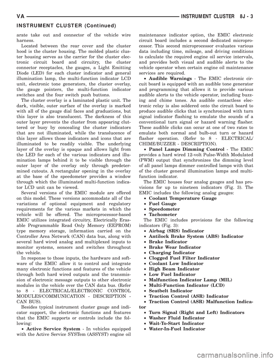
arate take out and connector of the vehicle wire
harness.
Located between the rear cover and the cluster
hood is the cluster housing. The molded plastic clus-
ter housing serves as the carrier for the cluster elec-
tronic circuit board and circuitry, the cluster
connector receptacles, the gauges, a Light Emitting
Diode (LED) for each cluster indicator and general
illumination lamp, the multi-function indicator LCD
unit, electronic tone generators, the cluster overlay,
the gauge pointers, the multi-function indicator
switches and the four switch push buttons.
The cluster overlay is a laminated plastic unit. The
dark, visible, outer surface of the overlay is marked
with all of the gauge dial faces and graduations, but
this layer is also translucent. The darkness of this
outer layer prevents the cluster from appearing clut-
tered or busy by concealing the cluster indicators
that are not illuminated, while the translucence of
this layer allows those indicators and icons that are
illuminated to be readily visible. The underlying
layer of the overlay is opaque and allows light from
the LED for each of the various indicators and illu-
mination lamps behind it to be visible through the
outer layer of the overlay only through predeter-
mined cutouts. A rectangular opening in the overlay
at the base of the speedometer provides a window
through which the illuminated multi-function indica-
tor LCD unit can be viewed.
Several versions of the EMIC module are offered
on this model. These versions accommodate all of the
variations of optional equipment and regulatory
requirements for the various markets in which the
vehicle will be offered. The microprocessor-based
EMIC utilizes integrated circuitry, Electrically Eras-
able Programmable Read Only Memory (EEPROM)
type memory storage, information carried on the
Controller Area Network (CAN) data bus, along with
several hard wired analog and multiplexed inputs to
monitor systems, sensors and switches throughout
the vehicle.
In response to those inputs, the hardware and soft-
ware of the EMIC allow it to control and integrate
many electronic functions and features of the vehicle
through both hard wired outputs and the transmis-
sion of electronic message outputs to other electronic
modules in the vehicle over the CAN data bus. (Refer
to 8 - ELECTRICAL/ELECTRONIC CONTROL
MODULES/COMMUNICATION - DESCRIPTION -
CAN BUS).
Besides typical instrument cluster gauge and indi-
cator support, the electronic functions and features
that the EMIC supports or controls include the fol-
lowing:
²Active Service System- In vehicles equipped
with the Active Service SYSTem (ASSYST) engine oilmaintenance indicator option, the EMIC electronic
circuit board includes a second dedicated micropro-
cessor. This second microprocessor evaluates various
data including time, mileage, and driving conditions
to calculate the required engine oil service intervals,
and provides both visual and audible alerts to the
vehicle operator when certain engine oil maintenance
services are required.
²Audible Warnings- The EMIC electronic cir-
cuit board is equipped with an audible tone generator
and programming that allows it to provide various
audible alerts to the vehicle operator, including buzz-
ing and chime tones. An audible contactless elec-
tronic relay is also soldered onto the circuit board to
produce audible clicks that is synchronized with turn
signal indicator flashing to emulate the sounds of a
conventional turn signal or hazard warning flasher.
These audible clicks can occur at one of two rates to
emulate both normal and bulb-out turn or hazard
flasher operation. (Refer to 8 - ELECTRICAL/
CHIME/BUZZER - DESCRIPTION).
²Panel Lamps Dimming Control- The EMIC
provides a hard wired 12-volt Pulse-Width Modulated
(PWM) output that synchronizes the dimming level
of all panel lamps dimmer controlled lamps with that
of the cluster general illumination lamps and multi-
function indicator.
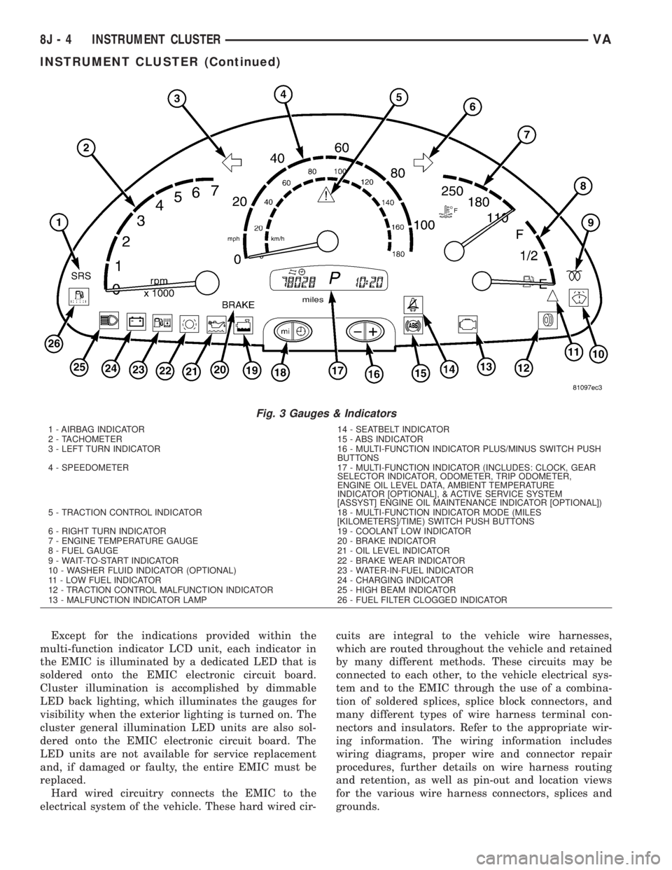
The EMIC houses four analog gauges and has pro-
visions for up to nineteen indicators (Fig. 3). The
EMIC includes the following analog gauges:
²Coolant Temperature Gauge
²Fuel Gauge
²Speedometer
²Tachometer
The EMIC includes provisions for the following
indicators (Fig. 3):
²Airbag (SRS) Indicator
²Antilock Brake System (ABS) Indicator
²Brake Indicator
²Brake Wear Indicator
²Charging Indicator
²Clogged Fuel Filter Indicator
²Coolant Low Indicator
²High Beam Indicator
²Low Fuel Indicator
²Malfunction Indicator Lamp (MIL)
²Multi-Function Indicator (LCD)
²Seatbelt Indicator
²Traction Control (ASR) Indicator
²Traction Control (ASR) Malfunction Indica-
tor
²Turn Signal (Right and Left) Indicators
²Washer Fluid Indicator
²Wait-To-Start Indicator
²Water-In-Fuel Indicator
VAINSTRUMENT CLUSTER 8J - 3
INSTRUMENT CLUSTER (Continued)
Page 174 of 1232
Except for the indications provided within the
multi-function indicator LCD unit, each indicator in
the EMIC is illuminated by a dedicated LED that is
soldered onto the EMIC electronic circuit board.
Cluster illumination is accomplished by dimmable
LED back lighting, which illuminates the gauges for
visibility when the exterior lighting is turned on. The
cluster general illumination LED units are also sol-
dered onto the EMIC electronic circuit board. The
LED units are not available for service replacement
and, if damaged or faulty, the entire EMIC must be
replaced.
Hard wired circuitry connects the EMIC to the
electrical system of the vehicle. These hard wired cir-cuits are integral to the vehicle wire harnesses,
which are routed throughout the vehicle and retained
by many different methods. These circuits may be
connected to each other, to the vehicle electrical sys-
tem and to the EMIC through the use of a combina-
tion of soldered splices, splice block connectors, and
many different types of wire harness terminal con-
nectors and insulators. Refer to the appropriate wir-
ing information. The wiring information includes
wiring diagrams, proper wire and connector repair
procedures, further details on wire harness routing
and retention, as well as pin-out and location views
for the various wire harness connectors, splices and
grounds.
Fig. 3 Gauges & Indicators
1 - AIRBAG INDICATOR 14 - SEATBELT INDICATOR
2 - TACHOMETER 15 - ABS INDICATOR
3 - LEFT TURN INDICATOR 16 - MULTI-FUNCTION INDICATOR PLUS/MINUS SWITCH PUSH
BUTTONS
4 - SPEEDOMETER 17 - MULTI-FUNCTION INDICATOR (INCLUDES: CLOCK, GEAR
SELECTOR INDICATOR, ODOMETER, TRIP ODOMETER,
ENGINE OIL LEVEL DATA, AMBIENT TEMPERATURE
INDICATOR [OPTIONAL], & ACTIVE SERVICE SYSTEM
[ASSYST] ENGINE OIL MAINTENANCE INDICATOR [OPTIONAL])
5 - TRACTION CONTROL INDICATOR 18 - MULTI-FUNCTION INDICATOR MODE (MILES
[KILOMETERS]/TIME) SWITCH PUSH BUTTONS
6 - RIGHT TURN INDICATOR 19 - COOLANT LOW INDICATOR
7 - ENGINE TEMPERATURE GAUGE 20 - BRAKE INDICATOR
8 - FUEL GAUGE 21 - OIL LEVEL INDICATOR
9 - WAIT-TO-START INDICATOR 22 - BRAKE WEAR INDICATOR
10 - WASHER FLUID INDICATOR (OPTIONAL) 23 - WATER-IN-FUEL INDICATOR
11 - LOW FUEL INDICATOR 24 - CHARGING INDICATOR
12 - TRACTION CONTROL MALFUNCTION INDICATOR 25 - HIGH BEAM INDICATOR
13 - MALFUNCTION INDICATOR LAMP 26 - FUEL FILTER CLOGGED INDICATOR
8J - 4 INSTRUMENT CLUSTERVA
INSTRUMENT CLUSTER (Continued)
Page 254 of 1232
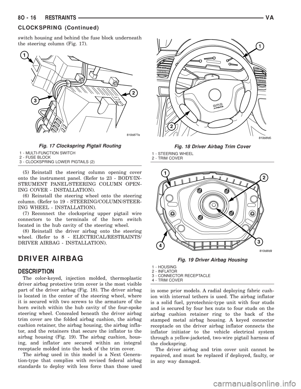
switch housing and behind the fuse block underneath
the steering column (Fig. 17).
(5) Reinstall the steering column opening cover
onto the instrument panel. (Refer to 23 - BODY/IN-
STRUMENT PANEL/STEERING COLUMN OPEN-
ING COVER - INSTALLATION).
(6) Reinstall the steering wheel onto the steering
column. (Refer to 19 - STEERING/COLUMN/STEER-
ING WHEEL - INSTALLATION).
(7) Reconnect the clockspring upper pigtail wire
connectors to the terminals of the horn switch
located in the hub cavity of the steering wheel.
(8) Reinstall the driver airbag onto the steering
wheel. (Refer to 8 - ELECTRICAL/RESTRAINTS/
DRIVER AIRBAG - INSTALLATION).
DRIVER AIRBAG
DESCRIPTION
The color-keyed, injection molded, thermoplastic
driver airbag protective trim cover is the most visible
part of the driver airbag (Fig. 18). The driver airbag
is located in the center of the steering wheel, where
it is secured with two screws to the armature of the
horn switch within the hub cavity of the four-spoke
steering wheel. Concealed beneath the driver airbag
trim cover are the folded airbag cushion, the airbag
cushion retainer, the airbag housing, the airbag infla-
tor, and the retainers that secure the inflator to the
airbag housing (Fig. 19). The airbag cushion, hous-
ing, and inflator are secured within an integral
receptacle molded into the back of the trim cover.
The airbag used in this model is a Next Genera-
tion-type that complies with revised federal airbag
standards to deploy with less force than those usedin some prior models. A radial deploying fabric cush-
ion with internal tethers is used. The airbag inflator
is a solid fuel, pyrotechnic-type unit with four studs
and is secured by four hex nuts to four studs on the
airbag cushion retainer ring to the back of the
stamped metal airbag housing. A keyed connector
receptacle on the driver airbag inflator connects the
inflator initiator to the vehicle electrical system
through a yellow-jacketed, two-wire pigtail harness of
the clockspring.
The driver airbag and trim cover unit cannot be
repaired, and must be replaced if deployed, faulty, or
in any way damaged.
Fig. 17 Clockspring Pigtail Routing
1 - MULTI-FUNCTION SWITCH
2 - FUSE BLOCK
3 - CLOCKSPRING LOWER PIGTAILS (2)
Fig. 18 Driver Airbag Trim Cover
1 - STEERING WHEEL
2 - TRIM COVER
Fig. 19 Driver Airbag Housing
1 - HOUSING
2 - INFLATOR
3 - CONNECTOR RECEPTACLE
4 - TRIM COVER
8O - 16 RESTRAINTSVA
CLOCKSPRING (Continued)
Page 262 of 1232
The passenger airbag unit used in this model is a
Next Generation-type that complies with revised fed-
eral airbag standards to deploy with less force than
those used in some prior models. The airbag housing
contains the folded airbag cushion, the airbag
retainer, and the airbag inflator. The airbag is a rect-
angular fabric cushion. The airbag inflator is a solid
fuel, pyrotechnic-type unit that is secured to and
sealed within the airbag housing along with the
folded airbag cushion. The inflator initiator connector
receptacle is connected to the vehicle electrical sys-
tem through a dedicated take out of the vehicle wire
harness with a yellow connector insulator.
The passenger airbag and airbag door unit cannot
be repaired, and must be replaced if deployed, faulty
or in any way damaged.
OPERATION
The passenger airbag is deployed by an electrical
signal generated by the Airbag Control Module
(ACM) through the passenger airbag squib circuits to
the initiator in the airbag inflator. When the ACM
sends the proper electrical signal to the initiator the
electrical energy generates enough heat to initiate a
small pyrotechnic charge which, in turn, ignites
chemical pellets within the inflator. Once ignited,
these chemical pellets burn rapidly and produce a
large quantity of inert gas. The inflator is sealed to
the back of the airbag housing and a diffuser in the
inflator directs all of the inert gas into the airbag
cushion, causing the cushion to inflate.
As the airbag cushion inflates, the passenger air-
bag door will unsnap from the clips that retain it to
the instrument panel at the top and bottom, then
pivot towards the top of the instrument panel and
out of the way on the woven straps. Following a pas-
senger airbag deployment, the airbag cushion quickly
deflates by venting the inert gas through the loose
weave of the fabric used to construct the back
(instrument panel side) of the airbag cushion.
Some of the chemicals used to create the inert gas
may be considered hazardous while in their solid
state before they are burned, but they are securely
sealed within the airbag inflator. However, the gas
that is produced when the chemicals are burned is
harmless. A small amount of residue from the burned
chemicals may cause some temporary discomfort if it
contacts the skin, eyes, or breathing passages. If skin
or eye irritation is noticed, rinse the affected area
with plenty of cool, clean water. If breathing pas-
sages are irritated, move to another area where there
is plenty of clean, fresh air to breath. If the irritation
is not alleviated by these actions, contact a physician
immediately.
REMOVAL
The following procedure is for replacement of a
faulty or damaged passenger airbag. If the airbag is
faulty or damaged, but not deployed, review the rec-
ommended procedures for handling non-deployed
supplemental restraints. (Refer to 8 - ELECTRICAL/
RESTRAINTS - STANDARD PROCEDURE - HAN-
DLING NON-DEPLOYED SUPPLEMENTAL
RESTRAINTS). If the passenger airbag has been
deployed, review the recommended procedures for
service after a supplemental restraint deployment
before removing the airbag from the vehicle. (Refer to
8 - ELECTRICAL/RESTRAINTS - STANDARD PRO-
CEDURE - SERVICE AFTER A SUPPLEMENTAL
RESTRAINT DEPLOYMENT).
WARNING: ON VEHICLES EQUIPPED WITH AIR-
BAGS, DISABLE THE SUPPLEMENTAL RESTRAINT
SYSTEM BEFORE ATTEMPTING ANY STEERING
WHEEL, STEERING COLUMN, DRIVER AIRBAG,
PASSENGER AIRBAG, SEAT BELT TENSIONER, OR
INSTRUMENT PANEL COMPONENT DIAGNOSIS OR
SERVICE. DISCONNECT AND ISOLATE THE BAT-
TERY NEGATIVE (GROUND) CABLE, THEN WAIT
TWO MINUTES FOR THE SYSTEM CAPACITOR TO
DISCHARGE BEFORE PERFORMING FURTHER
DIAGNOSIS OR SERVICE. THIS IS THE ONLY SURE
WAY TO DISABLE THE SUPPLEMENTAL
RESTRAINT SYSTEM. FAILURE TO TAKE THE
PROPER PRECAUTIONS COULD RESULT IN ACCI-
DENTAL AIRBAG DEPLOYMENT AND POSSIBLE
PERSONAL INJURY.
WARNING: WHEN REMOVING A DEPLOYED AIR-
BAG, RUBBER GLOVES, EYE PROTECTION, AND A
LONG-SLEEVED SHIRT SHOULD BE WORN. THERE
MAY BE DEPOSITS ON THE AIRBAG UNIT AND
OTHER INTERIOR SURFACES. IN LARGE DOSES,
THESE DEPOSITS MAY CAUSE IRRITATION TO THE
SKIN AND EYES.
(1) Disconnect and isolate the battery negative
cable. Wait two minutes for the system capacitor to
discharge before further service.
(2) Remove the instrument panel top cover tray
from over the passenger airbag (Fig. 29). (Refer to 23
- BODY/INSTRUMENT PANEL/INSTRUMENT
PANEL TOP COVER - TRAY - REMOVAL).
(3) Remove the two screws that secure the passen-
ger airbag door upper clips to the instrument panel
base trim.
8O - 24 RESTRAINTSVA
PASSENGER AIRBAG (Continued)