2005 MERCEDES-BENZ SPRINTER height
[x] Cancel search: heightPage 28 of 1232
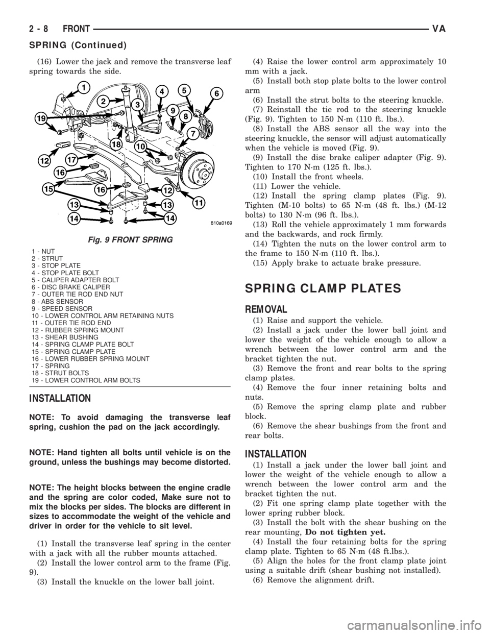
(16) Lower the jack and remove the transverse leaf
spring towards the side.
INSTALLATION
NOTE: To avoid damaging the transverse leaf
spring, cushion the pad on the jack accordingly.
NOTE: Hand tighten all bolts until vehicle is on the
ground, unless the bushings may become distorted.
NOTE: The height blocks between the engine cradle
and the spring are color coded, Make sure not to
mix the blocks per sides. The blocks are different in
sizes to accommodate the weight of the vehicle and
driver in order for the vehicle to sit level.
(1) Install the transverse leaf spring in the center
with a jack with all the rubber mounts attached.
(2) Install the lower control arm to the frame (Fig.
9).
(3) Install the knuckle on the lower ball joint.(4) Raise the lower control arm approximately 10
mm with a jack.
(5) Install both stop plate bolts to the lower control
arm
(6) Install the strut bolts to the steering knuckle.
(7) Reinstall the tie rod to the steering knuckle
(Fig. 9). Tighten to 150 N´m (110 ft. lbs.).
(8) Install the ABS sensor all the way into the
steering knuckle, the sensor will adjust automatically
when the vehicle is moved (Fig. 9).
(9) Install the disc brake caliper adapter (Fig. 9).
Tighten to 170 N´m (125 ft. lbs.).
(10) Install the front wheels.
(11) Lower the vehicle.
(12) Install the spring clamp plates (Fig. 9).
Tighten (M-10 bolts) to 65 N´m (48 ft. lbs.) (M-12
bolts) to 130 N´m (96 ft. lbs.).
(13) Roll the vehicle approximately 1 mm forwards
and the backwards, and rock firmly.
(14) Tighten the nuts on the lower control arm to
the frame to 150 N´m (110 ft. lbs.).
(15) Apply brake to actuate brake pressure.
SPRING CLAMP PLATES
REMOVAL
(1) Raise and support the vehicle.
(2) Install a jack under the lower ball joint and
lower the weight of the vehicle enough to allow a
wrench between the lower control arm and the
bracket tighten the nut.
(3) Remove the front and rear bolts to the spring
clamp plates.
(4) Remove the four inner retaining bolts and
nuts.
(5) Remove the spring clamp plate and rubber
block.
(6) Remove the shear bushings from the front and
rear bolts.
INSTALLATION
(1) Install a jack under the lower ball joint and
lower the weight of the vehicle enough to allow a
wrench between the lower control arm and the
bracket tighten the nut.
(2) Fit one spring clamp plate together with the
lower spring rubber block.
(3) Install the bolt with the shear bushing on the
rear mounting,Do not tighten yet.
(4) Install the four retaining bolts for the spring
clamp plate. Tighten to 65 N´m (48 ft.lbs.).
(5) Align the holes for the front clamp plate joint
using a suitable drift (shear bushing not installed).
(6) Remove the alignment drift.
Fig. 9 FRONT SPRING
1 - NUT
2 - STRUT
3 - STOP PLATE
4 - STOP PLATE BOLT
5 - CALIPER ADAPTER BOLT
6 - DISC BRAKE CALIPER
7 - OUTER TIE ROD END NUT
8 - ABS SENSOR
9 - SPEED SENSOR
10 - LOWER CONTROL ARM RETAINING NUTS
11 - OUTER TIE ROD END
12 - RUBBER SPRING MOUNT
13 - SHEAR BUSHING
14 - SPRING CLAMP PLATE BOLT
15 - SPRING CLAMP PLATE
16 - LOWER RUBBER SPRING MOUNT
17 - SPRING
18 - STRUT BOLTS
19 - LOWER CONTROL ARM BOLTS
2 - 8 FRONTVA
SPRING (Continued)
Page 31 of 1232
REAR
TABLE OF CONTENTS
page page
REAR
DESCRIPTION.........................11
DIAGNOSIS AND TESTING - SPRING AND
SHOCK.............................11
SPECIFICATIONS - TORQUE CHART........12
SHOCK
DIAGNOSIS AND TESTING - SHOCK........13
REMOVAL.............................13
INSTALLATION.........................13
SPRING
DESCRIPTION.........................14
OPERATION...........................14
REMOVAL
REMOVAL - (SRW)....................14REMOVAL - (DRW)....................14
INSTALLATION
INSTALLATION - (SRW).................14
INSTALLATION - (DRW).................15
SPRING SHACKLE
REMOVAL.............................15
INSTALLATION.........................15
STABILIZER BAR
REMOVAL.............................15
INSTALLATION.........................15
STABILIZER LINK
REMOVAL.............................16
INSTALLATION.........................16
REAR
DESCRIPTION
The rear suspension is comprised of:
²Shock Absorbers
²Jounce Bumpers
²Stabilizer Bar
²Leaf Springs
²Drive Axle
CAUTION: A vehicle should always be loaded so
the vehicle weight center-line is located immedi-
ately forward of the rear axle. Correct vehicle load-
ing provides proper front tire-to-road contact. This
results in maximum vehicle handling stability and
safety. Incorrect vehicle weight distribution can
cause excessive tire tread wear, spring fatigue or
failure, and erratic steering.
CAUTION: Suspension components with rubber/ure-
thane bushings (except stabilizer bar) should be
tightened with the vehicle at normal ride height. It is
important to have the springs supporting the weight
of the vehicle when the fasteners are torqued. If
springs are not at their normal ride position, vehicle
ride comfort could be affected and premature bush-
ing wear may occur.
DIAGNOSIS AND TESTING - SPRING AND
SHOCK
A knocking or rattling noise from a shock absorber
may be caused by movement between mounting
bushings and metal brackets or attaching compo-
nents. These noises can usually be stopped by tight-
ening the attaching nuts. If the noise persists,
inspect for damaged and worn bushings, and attach-
ing components. Repair as necessary if any of these
conditions exist.
A squeaking noise from the shock absorber may be
caused by the hydraulic valving and may be intermit-
tent. This condition is not repairable and the shock
absorber must be replaced.
The shock absorbers are not refillable or adjust-
able. If a malfunction occurs, the shock absorber
must be replaced. To test a shock absorber, hold it in
an upright position and force the piston in and out of
the cylinder four or five times. The action throughout
each stroke should be smooth and even.
The spring eye and shock absorber bushings do not
require any type of lubrication. Do not attempt to
stop spring bushing noise by lubricating them.
Grease and mineral oil-base lubricants will deterio-
rate the bushing rubber.
If the vehicle is used for severe, off-road operation,
the springs should be examined periodically. Check
for broken and shifted leafs, loose and missing clips,
and broken center bolts. Refer to Spring and Shock
Absorber Diagnosis chart for additional information.
VAREAR 2 - 11
Page 34 of 1232
SPRING
DESCRIPTION
The rear suspension system uses a multi-leaf
springs and a solid drive axle. The forward end of the
springs are mounted to the body rail hangers
through rubber bushings. The rearward end of the
springs are attached to the body by the use of shack-
les. The spring and shackles use rubber bushings.
OPERATION
The springs control ride quality and maintain vehi-
cle ride height. The shackles allow the springs to
change their length as the vehicle moves over various
road conditions.
REMOVAL
REMOVAL - (SRW)
(1) Raise and support the vehicle.
(2) Support the rear axle.
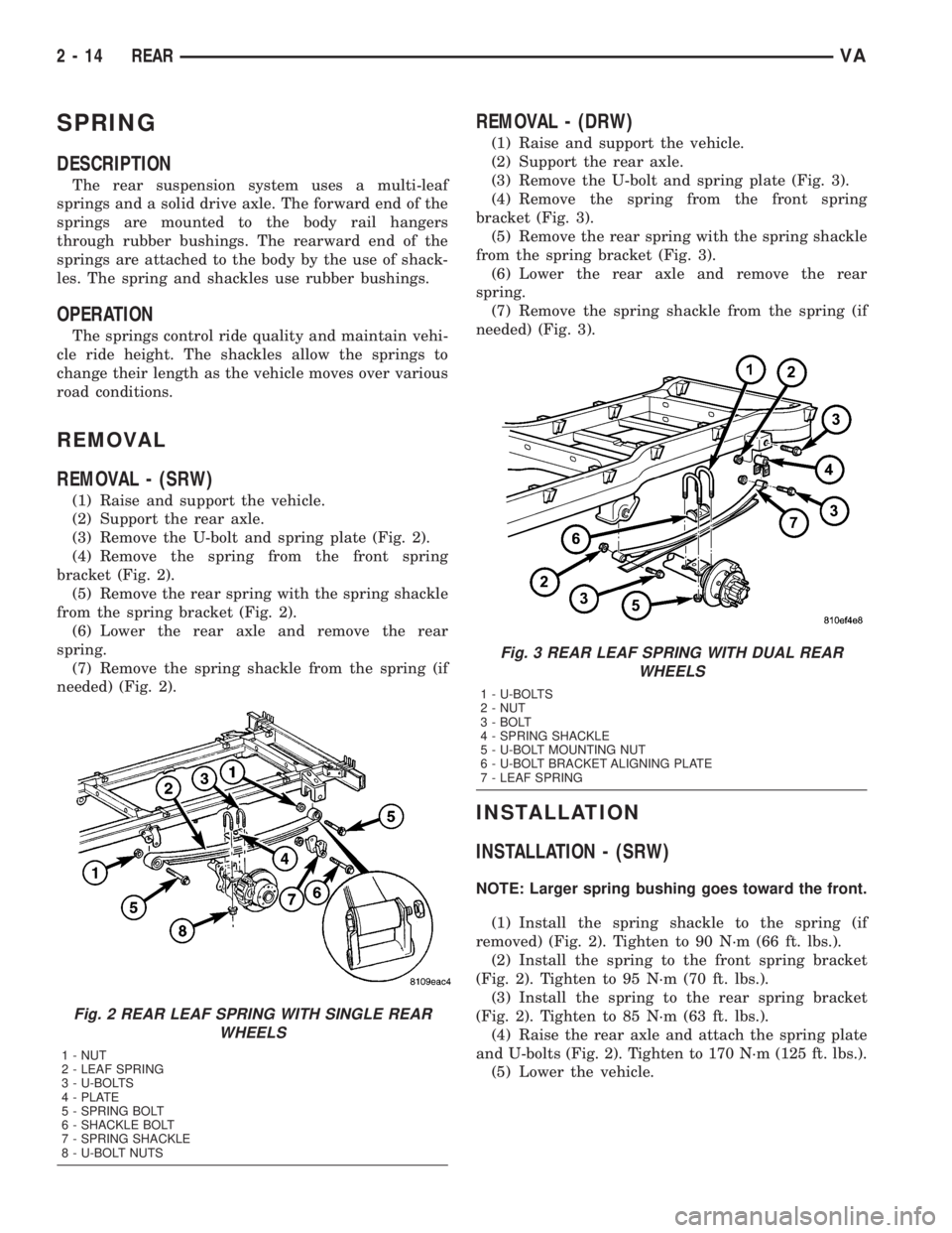
(3) Remove the U-bolt and spring plate (Fig. 2).
(4) Remove the spring from the front spring
bracket (Fig. 2).
(5) Remove the rear spring with the spring shackle
from the spring bracket (Fig. 2).
(6) Lower the rear axle and remove the rear
spring.
(7) Remove the spring shackle from the spring (if
needed) (Fig. 2).
REMOVAL - (DRW)
(1) Raise and support the vehicle.
(2) Support the rear axle.
(3) Remove the U-bolt and spring plate (Fig. 3).
(4) Remove the spring from the front spring
bracket (Fig. 3).
(5) Remove the rear spring with the spring shackle
from the spring bracket (Fig. 3).
(6) Lower the rear axle and remove the rear
spring.
(7) Remove the spring shackle from the spring (if
needed) (Fig. 3).
INSTALLATION
INSTALLATION - (SRW)
NOTE: Larger spring bushing goes toward the front.
(1) Install the spring shackle to the spring (if
removed) (Fig. 2). Tighten to 90 N´m (66 ft. lbs.).
(2) Install the spring to the front spring bracket
(Fig. 2). Tighten to 95 N´m (70 ft. lbs.).
(3) Install the spring to the rear spring bracket
(Fig. 2). Tighten to 85 N´m (63 ft. lbs.).
(4) Raise the rear axle and attach the spring plate
and U-bolts (Fig. 2). Tighten to 170 N´m (125 ft. lbs.).
(5) Lower the vehicle.
Fig. 2 REAR LEAF SPRING WITH SINGLE REAR
WHEELS
1 - NUT
2 - LEAF SPRING
3 - U-BOLTS
4 - PLATE
5 - SPRING BOLT
6 - SHACKLE BOLT
7 - SPRING SHACKLE
8 - U-BOLT NUTS
Fig. 3 REAR LEAF SPRING WITH DUAL REAR
WHEELS
1 - U-BOLTS
2 - NUT
3 - BOLT
4 - SPRING SHACKLE
5 - U-BOLT MOUNTING NUT
6 - U-BOLT BRACKET ALIGNING PLATE
7 - LEAF SPRING
2 - 14 REARVA
Page 37 of 1232
WHEEL ALIGNMENT
TABLE OF CONTENTS
page page
WHEEL ALIGNMENT
DESCRIPTION.........................17
DIAGNOSIS AND TESTING - PRE-ALIGNMENT
INSPECTION.........................17STANDARD PROCEDURE - TOE
ADJUSTMENT........................19
SPECIFICATIONS.......................19
WHEEL ALIGNMENT
DESCRIPTION
NOTE: Camber and Caster are not adjustable on
this vehicle. (TOE ONLY).
NOTE: Suspension components with rubber/ure-
thane bushings should be tightened with the vehi-
cle at normal ride height. It is important to have the
springs supporting the weight of the vehicle when
the fasteners are torqued. If springs are not at their
normal ride position, vehicle ride comfort could be
affected and premature bushing wear may occur.
Wheel alignment involves the correct positioning of
the wheels in relation to the vehicle. The positioning
is accomplished through suspension and steering
linkage adjustments. An alignment is considered
essential for efficient steering, good directional stabil-
ity and to minimize tire wear. The most important
measurements of an alignment are caster, camber
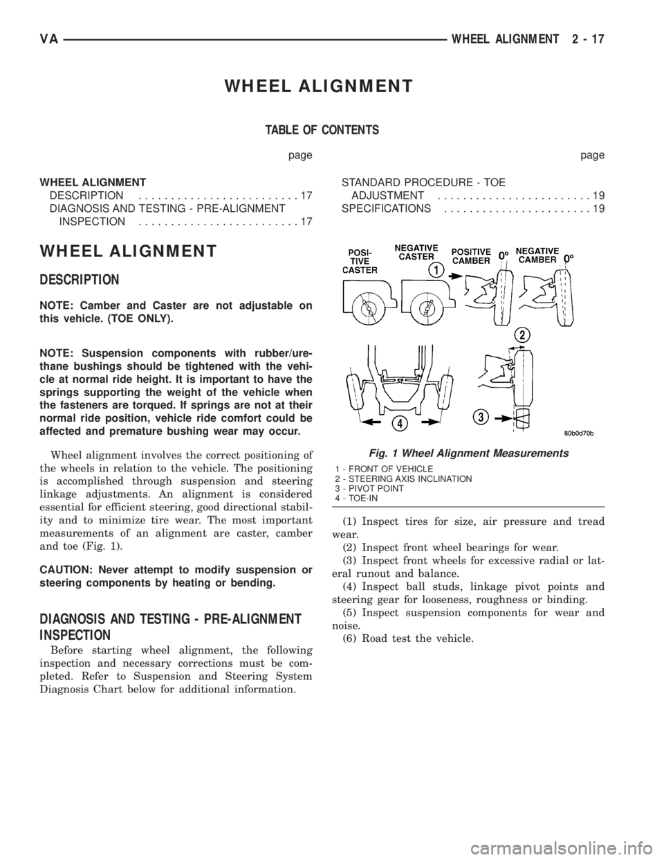
and toe (Fig. 1).
CAUTION: Never attempt to modify suspension or
steering components by heating or bending.
DIAGNOSIS AND TESTING - PRE-ALIGNMENT
INSPECTION
Before starting wheel alignment, the following
inspection and necessary corrections must be com-
pleted. Refer to Suspension and Steering System
Diagnosis Chart below for additional information.(1) Inspect tires for size, air pressure and tread
wear.
(2) Inspect front wheel bearings for wear.
(3) Inspect front wheels for excessive radial or lat-
eral runout and balance.
(4) Inspect ball studs, linkage pivot points and
steering gear for looseness, roughness or binding.
(5) Inspect suspension components for wear and
noise.
(6) Road test the vehicle.
Fig. 1 Wheel Alignment Measurements
1 - FRONT OF VEHICLE
2 - STEERING AXIS INCLINATION
3 - PIVOT POINT
4 - TOE-IN
VAWHEEL ALIGNMENT 2 - 17
Page 67 of 1232
ROAD TESTING
(1) If complaint involved low brake pedal, pump
pedal and note if it comes back up to normal height.
(2) Check brake pedal response with transmission
in Neutral and engine running. Pedal should remain
firm under constant foot pressure.
(3) During road test, make normal and firm brake
stops in 25-40 mph range. Note faulty brake opera-
tion such as low pedal, hard pedal, fade, pedal pulsa-
tion, pull, grab, drag, noise, etc.
(4) Attempt to stop the vehicle with the parking
brake only and note grab, drag, noise, etc.
PEDAL FALLS AWAY
A brake pedal that falls away under steady foot
pressure is generally the result of a system leak. The
leak point could be at a brake line, fitting, hose, or
caliper/wheel cylinder. If leakage is severe, fluid will
be evident at or around the leaking component.
Internal leakage (seal by-pass) in the master cylin-
der caused by worn or damaged piston cups, may
also be the problem cause.
An internal leak in the ABS or RWAL system may
also be the problem with no physical evidence.
LOW PEDAL
If a low pedal is experienced, pump the pedal sev-
eral times. If the pedal comes back up worn linings,
rotors, drums, or rear brakes out of adjustment are
the most likely causes. The proper course of action is
to inspect and replace all worn component and make
the proper adjustments.
SPONGY PEDAL
A spongy pedal is most often caused by air in the
system. However, thin brake drums or substandard
brake lines and hoses can also cause a spongy pedal.
The proper course of action is to bleed the system,
and replace thin drums and substandard quality
brake hoses if suspected.
HARD PEDAL OR HIGH PEDAL EFFORT
A hard pedal or high pedal effort may be due to
lining that is water soaked, contaminated, glazed, or
badly worn. The power booster or check valve could
also be faulty.
PEDAL PULSATION
Pedal pulsation is caused by components that are
loose, or beyond tolerance limits.
The primary cause of pulsation are disc brake
rotors with excessive lateral runout or thickness vari-
ation, or out of round brake drums. Other causes are
loose wheel bearings or calipers and worn, damaged
tires.NOTE: Some pedal pulsation may be felt during
ABS activation.
BRAKE DRAG
Brake drag occurs when the lining is in constant
contact with the rotor or drum. Drag can occur at one
wheel, all wheels, fronts only, or rears only.
Drag is a product of incomplete brake shoe release.
Drag can be minor or severe enough to overheat the
linings, rotors and drums.
Minor drag will usually cause slight surface char-
ring of the lining. It can also generate hard spots in
rotors and drums from the overheat-cool down pro-
cess. In most cases, the rotors, drums, wheels and
tires are quite warm to the touch after the vehicle is
stopped.
Severe drag can char the brake lining all the way
through. It can also distort and score rotors and
drums to the point of replacement. The wheels, tires
and brake components will be extremely hot. In
severe cases, the lining may generate smoke as it
chars from overheating.
Common causes of brake drag are:
²Seized or improperly adjusted parking brake
cables.
²Loose/worn wheel bearing.
²Seized caliper or wheel cylinder piston.
²Caliper binding on corroded bushings or rusted
slide surfaces.
²Loose caliper mounting.
²Drum brake shoes binding on worn/damaged
support plates.
²Mis-assembled components.
²Long booster output rod.
If brake drag occurs at all wheels, the problem
may be related to a blocked master cylinder return
port, or faulty power booster (binds-does not release).
BRAKE FADE
Brake fade is usually a product of overheating
caused by brake drag. However, brake overheating
and resulting fade can also be caused by riding the
brake pedal, making repeated high deceleration stops
in a short time span, or constant braking on steep
mountain roads. Refer to the Brake Drag information
in this section for causes.
BRAKE PULL
Front brake pull condition could result from:
²Contaminated lining in one caliper
²Seized caliper piston
²Binding caliper
²Loose caliper
²Rusty caliper slide surfaces
²Improper brake pads
²Damaged rotor
VABRAKES - BASE 5 - 3
BRAKES - BASE (Continued)
Page 159 of 1232
INSTALLATION
(1) Raise and support vehicle.
(2) Position starter motor to transmission housing.
(3) Install 2 mounting bolts. Refer to Torque Spec-
ifications.
(4) Lower vehicle.
(5) Connect battery cable and solenoid wiring to
solenoid (2 nuts). Refer to Torque Specifications.
(6) Position wiring harness trough and install
retaining bolt.
(7) Install new nylon tie-wraps to wiring trough.
(8) Connect negative battery cable.
STARTER MOTOR RELAY
DESCRIPTION
The starter relay is an electromechanical device
that switches battery current to the pull-in coil of the
starter solenoid when ignition switch is turned to
Start position. The starter relay is located in the
Fuse/Relay Block. The Fuse/Relay Block is located
under, and to the left side of the drivers seat. See
Fuse/Relay Block cover for relay identification and
location.
The starter relay is an International Standards
Organization (ISO) relay. Relays conforming to ISO
specifications have common physical dimensions, cur-
rent capacities, terminal patterns, and terminal func-
tions.
The starter relay cannot be repaired or adjusted
and, if faulty or damaged, it must be replaced.
REMOVAL
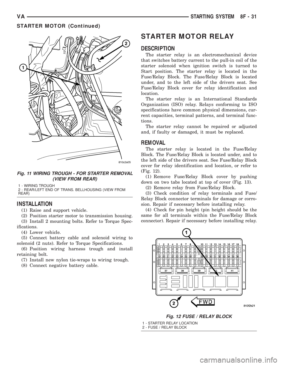
The starter relay is located in the Fuse/Relay
Block. The Fuse/Relay Block is located under, and to
the left side of the drivers seat. See Fuse/Relay Block
cover for relay identification and location, or refer to
(Fig. 12).
(1) Remove Fuse/Relay Block cover by pushing
down on two tabs located at top of cover (Fig. 13).
(2) Remove relay from Fuse/Relay Block.
(3) Check condition of relay terminals and Fuse/
Relay Block connector terminals for damage or corro-
sion. Repair if necessary before installing relay.
(4) Check for pin height (pin height should be the
same for all terminals within the Fuse/Relay Block
connector). Repair if necessary before installing relay.
Fig. 11 WIRING TROUGH - FOR STARTER REMOVAL
(VIEW FROM REAR)
1 - WIRING TROUGH
2 - REAR/LEFT END OF TRANS. BELLHOUSING (VIEW FROM
REAR)
Fig. 12 FUSE / RELAY BLOCK
1 - STARTER RELAY LOCATION
2 - FUSE / RELAY BLOCK
VASTARTING SYSTEM 8F - 31
STARTER MOTOR (Continued)
Page 241 of 1232
ACTIVE RESTRAINTS
The active restraints for this model include:
²Front Seat Belts- Both outboard front seating
positions are equipped with three-point seat belt sys-
tems employing a lower B-pillar mounted inertia
latch-type retractors, height-adjustable upper B-pil-
lar mounted turning loops, travelling lower seat belt
anchors secured to the outboard seat tracks, and
travelling end-release seat belt buckles secured to
the inboard seat track. The driver side front seat belt
buckle of all models includes an integral seat belt
switch that detects whether its seat belt has been
fastened.
²Rear Seat Belts- All rear seating positions are
equipped with three-point seat belt systems. Each
rear seating position belt employs an integral seat
cushion frame mounted inertia latch-type retractor, a
fixed position upper seat back frame mounted turn-
ing loop, and a fixed lower seat belt anchor secured
to the seat cushion frame. All rear seat belts have
fixed end-release seat belt buckles that are also
secured to the seat cushion frame.
PASSIVE RESTRAINTS
A Next Generation driver airbag is standard facto-
ry-installed safety equipment on this model, while a
passenger side front airbag is optional. This airbag
system is a passive, inflatable, Supplemental
Restraint System (SRS) and vehicles with this equip-
ment can be readily identified by the ªSRS - AIR-
BAGº logo molded into the driver airbag trim cover
in the center of the steering wheel and, if the vehicle
is so equipped, also into the passenger airbag door on
the instrument panel above the glove box (Fig. 2).
Vehicles with the airbag system can also be identified
by the airbag indicator, which will illuminate in the
instrument cluster for about six seconds as a bulb
test each time the ignition switch is turned to the On
position. A pyrotechnic-type seat belt tensioner is
integral to the front seat belt retractor mounted on
the lower B-pillar on the driver side, and to the pas-
senger side retractor of vehicles equipped with the
optional passenger side airbag.
The supplemental restraint system includes the
following major components, which are described in
further detail elsewhere in this service information:
²Airbag Control Module- The Airbag Control
Module (ACM) is located on a mount on the floor
panel within the driver side seat riser, beneath the
driver seat in the passenger compartment.
²Airbag (SRS) Indicator- The airbag indicator
is integral to the ElectroMechanical Instrument Clus-
ter (EMIC), which is located on the instrument panel
in front of the driver.²Clockspring- The clockspring is located near
the top of the steering column, directly beneath the
steering wheel.
²Driver Airbag- The driver airbag is located in
the center of the steering wheel, beneath the driver
airbag trim cover.
²Driver Knee Blocker- The structure of the
lower instrument panel serves as a knee blocker for
the driver.
²Passenger Airbag- The optional passenger air-
bag is located within the instrument panel, behind
the passenger airbag door on the instrument panel
above the glove box on the passenger side of the vehi-
cle.
²Passenger Knee Blocker- The structure of
the glove box door and the lower instrument panel
serve as a knee blocker for the front seat passenger.
²Seat Belt Tensioner- A seat belt tensioner is
integral to the driver side front seat belt retractor
unit, and to the passenger side front seat belt retrac-
tor unit on vehicles equipped with an optional pas-
senger airbag.
The ACM contains a central processing unit and
programming that allows it to communicate on a
serial data bus diagnostic circuit connected to the
16-way Data Link Connector (DLC) located below the
left end of the instrument panel. This method of com-
munication is used for initialization of the ACM and
for diagnosis of the SRS circuits and components
using a DRBIIItscan tool.
Hard wired circuitry connects the supplemental
restraint system components to each other through
the electrical system of the vehicle. These hard wired
circuits are integral to several wire harnesses, which
are routed throughout the vehicle and retained by
many different methods. These circuits may be con-
nected to each other, to the vehicle electrical system,
and to the supplemental restraint system compo-
nents through the use of a combination of soldered
Fig. 2 SRS Logo
VARESTRAINTS 8O - 3
RESTRAINTS (Continued)
Page 258 of 1232
(2) Disconnect and isolate the battery negative
cable. Wait two minutes for the system capacitor to
discharge before further service.
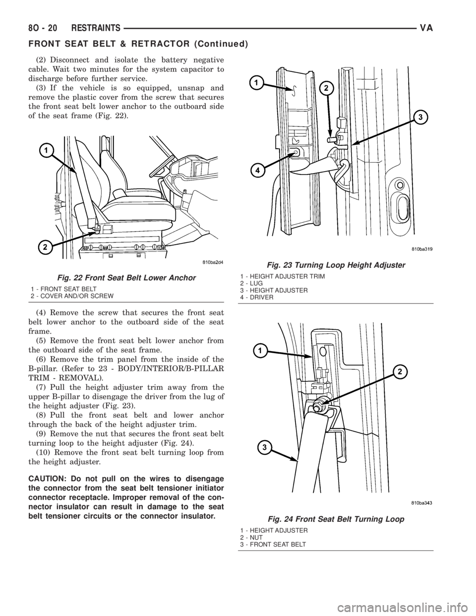
(3) If the vehicle is so equipped, unsnap and
remove the plastic cover from the screw that secures
the front seat belt lower anchor to the outboard side
of the seat frame (Fig. 22).
(4) Remove the screw that secures the front seat
belt lower anchor to the outboard side of the seat
frame.
(5) Remove the front seat belt lower anchor from
the outboard side of the seat frame.
(6) Remove the trim panel from the inside of the
B-pillar. (Refer to 23 - BODY/INTERIOR/B-PILLAR
TRIM - REMOVAL).
(7) Pull the height adjuster trim away from the
upper B-pillar to disengage the driver from the lug of
the height adjuster (Fig. 23).
(8) Pull the front seat belt and lower anchor
through the back of the height adjuster trim.
(9) Remove the nut that secures the front seat belt
turning loop to the height adjuster (Fig. 24).
(10) Remove the front seat belt turning loop from
the height adjuster.
CAUTION: Do not pull on the wires to disengage
the connector from the seat belt tensioner initiator
connector receptacle. Improper removal of the con-
nector insulator can result in damage to the seat
belt tensioner circuits or the connector insulator.
Fig. 22 Front Seat Belt Lower Anchor
1 - FRONT SEAT BELT
2 - COVER AND/OR SCREW
Fig. 23 Turning Loop Height Adjuster
1 - HEIGHT ADJUSTER TRIM
2 - LUG
3 - HEIGHT ADJUSTER
4 - DRIVER
Fig. 24 Front Seat Belt Turning Loop
1 - HEIGHT ADJUSTER
2 - NUT
3 - FRONT SEAT BELT
8O - 20 RESTRAINTSVA
FRONT SEAT BELT & RETRACTOR (Continued)