2005 MERCEDES-BENZ SPRINTER immobilizer
[x] Cancel search: immobilizerPage 172 of 1232

INSTRUMENT CLUSTER
DESCRIPTION
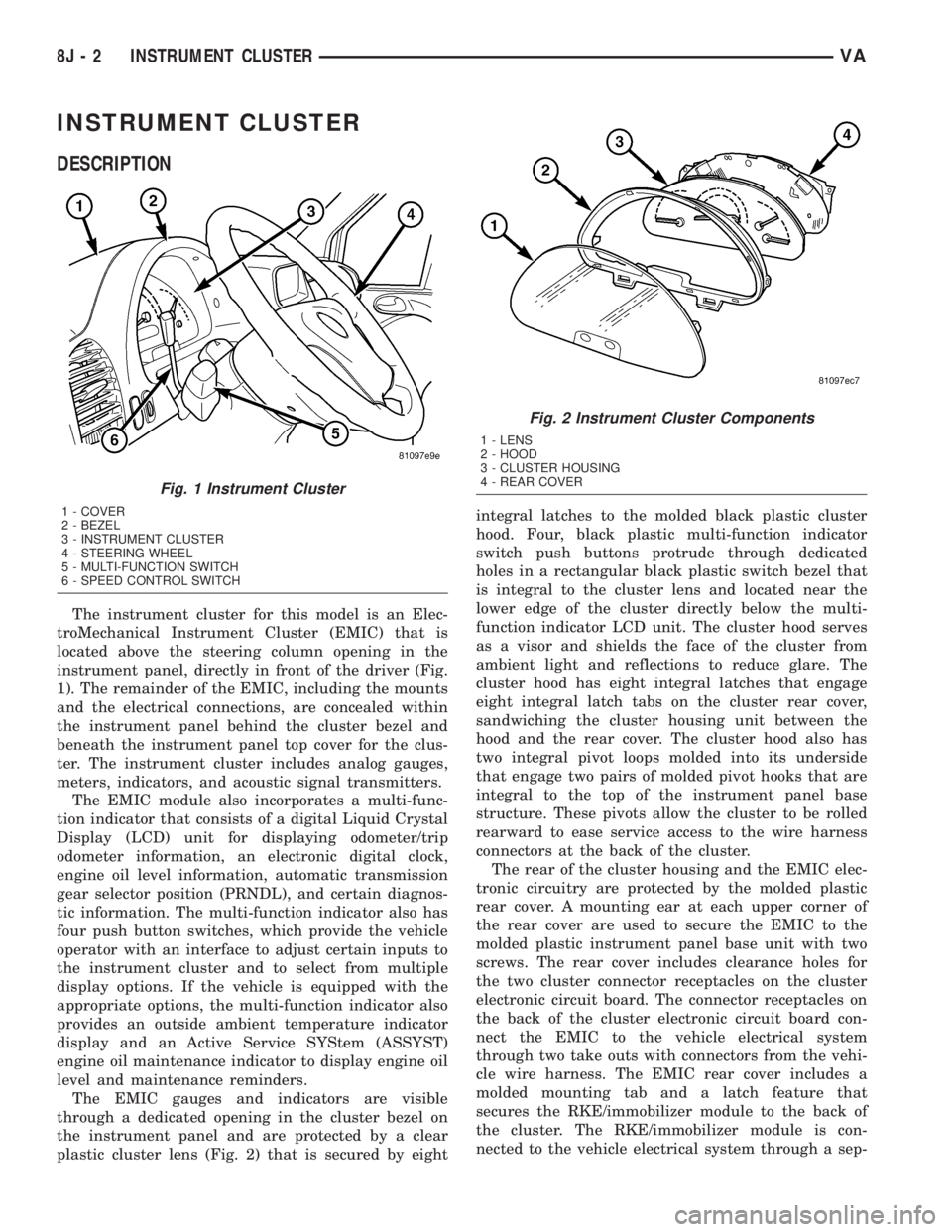
The instrument cluster for this model is an Elec-
troMechanical Instrument Cluster (EMIC) that is
located above the steering column opening in the
instrument panel, directly in front of the driver (Fig.
1). The remainder of the EMIC, including the mounts
and the electrical connections, are concealed within
the instrument panel behind the cluster bezel and
beneath the instrument panel top cover for the clus-
ter. The instrument cluster includes analog gauges,
meters, indicators, and acoustic signal transmitters.
The EMIC module also incorporates a multi-func-
tion indicator that consists of a digital Liquid Crystal
Display (LCD) unit for displaying odometer/trip
odometer information, an electronic digital clock,
engine oil level information, automatic transmission
gear selector position (PRNDL), and certain diagnos-
tic information. The multi-function indicator also has
four push button switches, which provide the vehicle
operator with an interface to adjust certain inputs to
the instrument cluster and to select from multiple
display options. If the vehicle is equipped with the
appropriate options, the multi-function indicator also
provides an outside ambient temperature indicator
display and an Active Service SYStem (ASSYST)
engine oil maintenance indicator to display engine oil
level and maintenance reminders.
The EMIC gauges and indicators are visible
through a dedicated opening in the cluster bezel on
the instrument panel and are protected by a clear
plastic cluster lens (Fig. 2) that is secured by eightintegral latches to the molded black plastic cluster
hood. Four, black plastic multi-function indicator
switch push buttons protrude through dedicated
holes in a rectangular black plastic switch bezel that
is integral to the cluster lens and located near the
lower edge of the cluster directly below the multi-
function indicator LCD unit. The cluster hood serves
as a visor and shields the face of the cluster from
ambient light and reflections to reduce glare. The
cluster hood has eight integral latches that engage
eight integral latch tabs on the cluster rear cover,
sandwiching the cluster housing unit between the
hood and the rear cover. The cluster hood also has
two integral pivot loops molded into its underside
that engage two pairs of molded pivot hooks that are
integral to the top of the instrument panel base
structure. These pivots allow the cluster to be rolled
rearward to ease service access to the wire harness
connectors at the back of the cluster.
The rear of the cluster housing and the EMIC elec-
tronic circuitry are protected by the molded plastic
rear cover. A mounting ear at each upper corner of
the rear cover are used to secure the EMIC to the
molded plastic instrument panel base unit with two
screws. The rear cover includes clearance holes for
the two cluster connector receptacles on the cluster
electronic circuit board. The connector receptacles on
the back of the cluster electronic circuit board con-
nect the EMIC to the vehicle electrical system
through two take outs with connectors from the vehi-
cle wire harness. The EMIC rear cover includes a
molded mounting tab and a latch feature that
secures the RKE/immobilizer module to the back of
the cluster. The RKE/immobilizer module is con-
nected to the vehicle electrical system through a sep-
Fig. 1 Instrument Cluster
1 - COVER
2 - BEZEL
3 - INSTRUMENT CLUSTER
4 - STEERING WHEEL
5 - MULTI-FUNCTION SWITCH
6 - SPEED CONTROL SWITCH
Fig. 2 Instrument Cluster Components
1 - LENS
2 - HOOD
3 - CLUSTER HOUSING
4 - REAR COVER
8J - 2 INSTRUMENT CLUSTERVA
Page 178 of 1232

(3) Remove the cluster top cover from the instru-
ment panel. (Refer to 23 - BODY/INSTRUMENT
PANEL/TOP COVER - CLUSTER - REMOVAL).
(4) Remove the two screws that secure the instru-
ment cluster mounting ears to the instrument panel
base structure (Fig. 4).
(5) Roll the top of the instrument cluster rearward
far enough to access and release the latch that
secures the RKE/immobilizer module to the back of
the instrument cluster rear cover and disengage the
module from the cluster (Fig. 5).
(6) Depress the release (Arrow A) and lift the lever
arm (Arrow B) to disconnect each of the two frame
wire harness connectors for the cluster from the con-
nector receptacles on the back of the cluster housing
(Fig. 6).
(7) Lift the instrument cluster upward far enough
to disengage the two molded plastic pivot loops inte-
gral to the base of the cluster hood from the two
pairs of molded plastic pivot hooks that are integral
to the top of the instrument panel base structure.
(8) Remove the instrument cluster from the instru-
ment panel.
Fig. 4 Instrument Cluster Remove/Install
1 - SCREW (2)
2 - COVER
3 - SCREW (2)
4 - INSTRUMENT CLUSTER
5 - LOOP (2)
Fig. 5 RKE/Immobilizer Module
1 - RKE/IMMOBILIZER MODULE
2-LATCH
3 - INSTRUMENT CLUSTER
Fig. 6 Cluster Connectors
1 - STEERING WHEEL
2 - INSTRUMENT CLUSTER
3 - CONNECTOR (2)
8J - 8 INSTRUMENT CLUSTERVA
INSTRUMENT CLUSTER (Continued)
Page 179 of 1232

INSTALLATION
WARNING: ON VEHICLES EQUIPPED WITH AIR-
BAGS, DISABLE THE SUPPLEMENTAL RESTRAINT
SYSTEM BEFORE ATTEMPTING ANY STEERING
WHEEL, STEERING COLUMN, DRIVER AIRBAG,
PASSENGER AIRBAG, SEAT BELT TENSIONER, OR
INSTRUMENT PANEL COMPONENT DIAGNOSIS OR
SERVICE. DISCONNECT AND ISOLATE THE BAT-
TERY NEGATIVE (GROUND) CABLE, THEN WAIT
TWO MINUTES FOR THE SYSTEM CAPACITOR TO
DISCHARGE BEFORE PERFORMING FURTHER
DIAGNOSIS OR SERVICE. THIS IS THE ONLY SURE
WAY TO DISABLE THE SUPPLEMENTAL
RESTRAINT SYSTEM. FAILURE TO TAKE THE
PROPER PRECAUTIONS COULD RESULT IN ACCI-
DENTAL SUPPLEMENTAL RESTRAINT DEPLOY-
MENT AND POSSIBLE PERSONAL INJURY.
(1) Position the instrument cluster to the instru-
ment panel.
(2) Align the two molded plastic pivot loops inte-
gral to the base of the cluster hood between the two
pairs of molded plastic pivot hooks that are integral
to the top of instrument panel base structure, then
push downward on the top of the cluster until the
loops snap into engagement with the hooks (Fig. 6).
(3) Roll the top of the instrument cluster rearward
to access, reconnect, and latch the two frame wire
harness connectors for the cluster to the connector
receptacles on the back of the cluster housing.
(4) Engage and latch the RKE/immobilizer module
to the back of the instrument cluster rear cover (Fig.
5)
(5) Roll the top of the instrument cluster forward
to position the instrument cluster into the instru-
ment panel.
(6) Install and tighten the two screws that secure
the instrument cluster mounting ears to the instru-
ment panel base structure (Fig. 4). Tighten the
screws to 2 N´m (20 in. lbs.).
(7) Reinstall the cluster top cover onto the instru-
ment panel. (Refer to 23 - BODY/INSTRUMENT
PANEL/TOP COVER - CLUSTER - INSTALLA-
TION).
(8) Reinstall the cluster bezel onto the instrument
panel. (Refer to 23 - BODY/INSTRUMENT PANEL/
CLUSTER BEZEL - INSTALLATION).
(9) Reconnect the battery negative cable.
ABS INDICATOR
DESCRIPTION
An Anti-lock Brake System (ABS) indicator is stan-
dard equipment on all instrument clusters. The ABS
indicator is located near the lower edge of the instru-
ment cluster, to the right of the multi-function indi-
cator display. The ABS indicator consists of the
International Control and Display Symbol icon for
ªFailure of Anti-lock Braking Systemº imprinted
within a rectangular cutout in the opaque layer of
the instrument cluster overlay. The dark outer layer
of the overlay prevents the indicator from being
clearly visible when it is not illuminated. An amber
Light Emitting Diode (LED) behind the cutout in the
opaque layer of the overlay causes the icon to appear
silhouetted against an amber field through the trans-
lucent outer layer of the overlay when the indicator
is illuminated from behind by the LED, which is sol-
dered onto the instrument cluster electronic circuit
board. The ABS indicator is serviced as a unit with
the instrument cluster.
OPERATION
The ABS indicator gives an indication to the vehi-
cle operator when the ABS or the electronic brake
force distribution (EBV) systems are faulty or inoper-
ative. This indicator is controlled by a transistor on
the instrument cluster circuit board based upon clus-
ter programming and electronic messages received by
the cluster from the Controller Antilock Brake (CAB)
over the Controller Area Network (CAN) data bus.
The ABS indicator Light Emitting Diode (LED) is
completely controlled by the instrument cluster logic
circuit, and that logic will only allow this indicator to
operate when the instrument cluster detects that the
ignition switch is in the On position. Therefore, the
LED will always be off when the ignition switch is in
any position except On. The LED only illuminates
when it is provided a path to ground by the instru-
ment cluster transistor. The instrument cluster will
turn on the ABS indicator for the following reasons:
²Bulb Test- Each time the ignition switch is
turned to the On position the ABS indicator is illu-
minated by the cluster for about two seconds as a
bulb test.
VAINSTRUMENT CLUSTER 8J - 9
INSTRUMENT CLUSTER (Continued)
Page 278 of 1232

INTRUSION SENSOR
REMOVAL
(1) Disconnect and isolate the battery negative
cable.
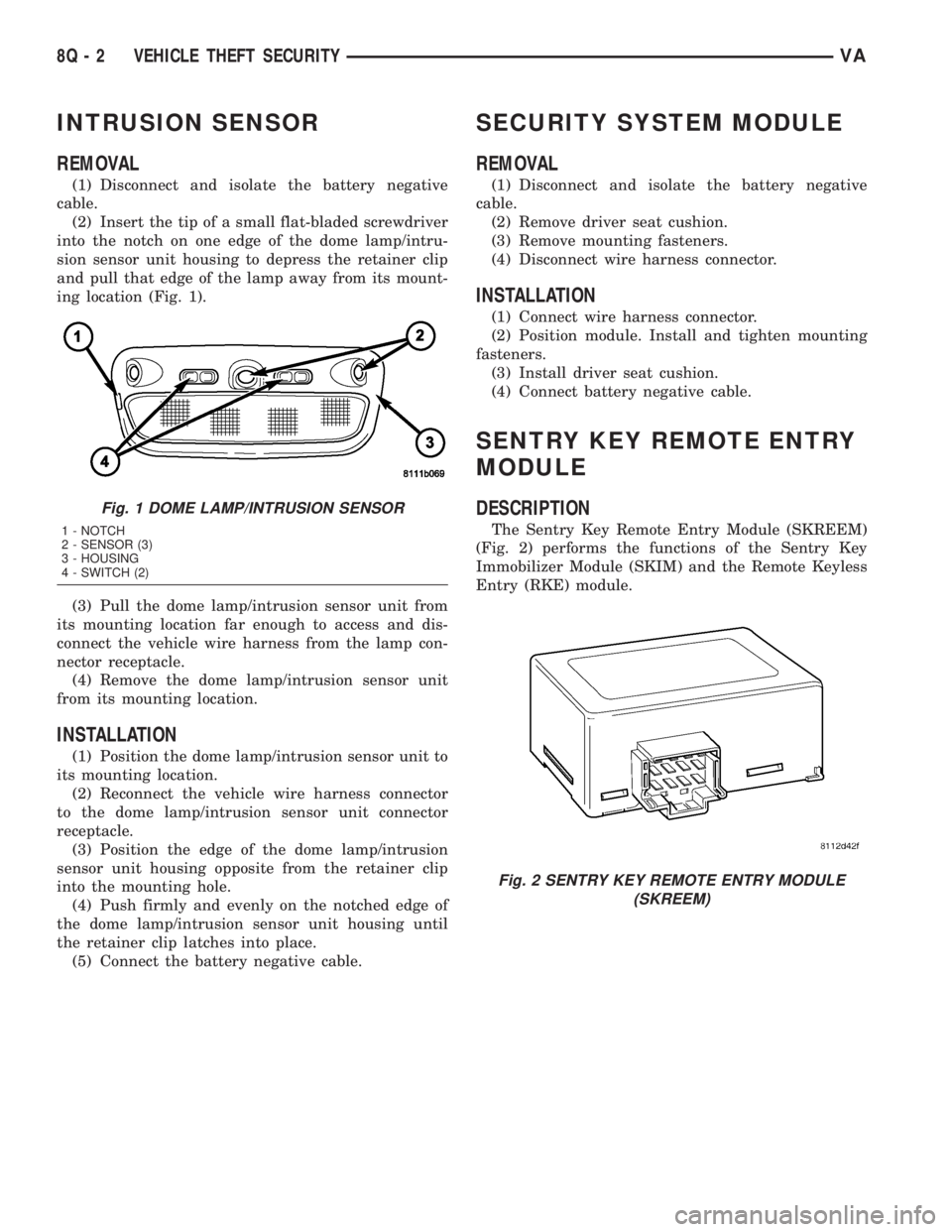
(2) Insert the tip of a small flat-bladed screwdriver
into the notch on one edge of the dome lamp/intru-
sion sensor unit housing to depress the retainer clip
and pull that edge of the lamp away from its mount-
ing location (Fig. 1).
(3) Pull the dome lamp/intrusion sensor unit from
its mounting location far enough to access and dis-
connect the vehicle wire harness from the lamp con-
nector receptacle.
(4) Remove the dome lamp/intrusion sensor unit
from its mounting location.
INSTALLATION
(1) Position the dome lamp/intrusion sensor unit to
its mounting location.
(2) Reconnect the vehicle wire harness connector
to the dome lamp/intrusion sensor unit connector
receptacle.
(3) Position the edge of the dome lamp/intrusion
sensor unit housing opposite from the retainer clip
into the mounting hole.
(4) Push firmly and evenly on the notched edge of
the dome lamp/intrusion sensor unit housing until
the retainer clip latches into place.
(5) Connect the battery negative cable.
SECURITY SYSTEM MODULE
REMOVAL
(1) Disconnect and isolate the battery negative
cable.
(2) Remove driver seat cushion.
(3) Remove mounting fasteners.
(4) Disconnect wire harness connector.
INSTALLATION
(1) Connect wire harness connector.
(2) Position module. Install and tighten mounting
fasteners.
(3) Install driver seat cushion.
(4) Connect battery negative cable.
SENTRY KEY REMOTE ENTRY
MODULE
DESCRIPTION
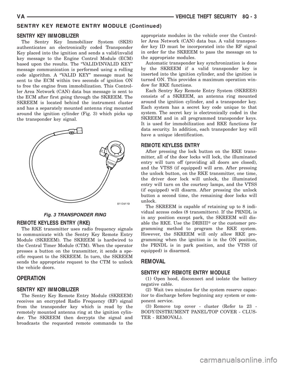
The Sentry Key Remote Entry Module (SKREEM)
(Fig. 2) performs the functions of the Sentry Key
Immobilizer Module (SKIM) and the Remote Keyless
Entry (RKE) module.
Fig. 1 DOME LAMP/INTRUSION SENSOR
1 - NOTCH
2 - SENSOR (3)
3 - HOUSING
4 - SWITCH (2)
Fig. 2 SENTRY KEY REMOTE ENTRY MODULE
(SKREEM)
8Q - 2 VEHICLE THEFT SECURITYVA
Page 279 of 1232

SENTRY KEY IMMOBILIZER
The Sentry Key Immobilizer System (SKIS)
authenticates an electronically coded Transponder
Key placed into the ignition and sends a valid/invalid
key message to the Engine Control Module (ECM)
based upon the results. The ªVALID/INVALID KEYº
message communication is performed using a rolling
code algorithm. A ªVALID KEYº message must be
sent to the ECM within two seconds of ignition ON
to free the engine from immobilization. This Control-
ler Area Network (CAN) data bus message is sent to
the ECM after first going through the SKREEM. The
SKREEM is located behind the instrument cluster
and has a separately mounted antenna ring mounted
around the ignition cylinder (Fig. 3) which picks up
the transponder key signal.
REMOTE KEYLESS ENTRY (RKE)
The RKE transmitter uses radio frequency signals
to communicate with the Sentry Key Remote Entry
Module (SKREEM). The SKREEM is hardwired to
the Central Timer Module (CTM). When the operator
presses a button on the transmitter, it sends a spe-
cific request to the SKREEM. In turn, the SKREEM
sends the appropriate request to the CTM to unlock
the vehicle doors.
OPERATION
SENTRY KEY IMMOBILIZER
The Sentry Key Remote Entry Module (SKREEM)
receives an encrypted Radio Frequency (RF) signal
from the transponder key which is read by the
remotely mounted antenna ring at the ignition cylin-
der. The SKREEM then decrypts the signal and
broadcasts the requested remote commands to theappropriate modules in the vehicle over the Control-
ler Area Network (CAN) data bus. A valid transpon-
der key ID must be incorporated into the RF signal
in order for the SKREEM to pass the message on to
the appropriate modules.
Automatic transponder key synchronization is done
by the SKREEM if a valid transponder key is
inserted into the ignition cylinder, and the ignition is
turned ON. This provides a maximum operation win-
dow for RKE functions.
Each Sentry Key Remote Entry System (SKREES)
consists of a SKREEM, an antenna ring mounted
around the ignition cylinder, and a transponder key.
Each system has a secret key code unique to that
system. The secret key is electronically coded in the
SKREEM and in all programmed transponder keys.
It is used for immobilization and RKE functions for
data security. In addition, each transponder key will
have a unique identification.
REMOTE KEYLESS ENTRY
After pressing the lock button on the RKE trans-
mitter, all of the door locks will lock, the illuminated
entry will turn off (providing all doors are closed),
and the VTSS (if equipped) will arm. After pressing
the unlock button, on the RKE transmitter, one time,
the driver door lock will unlock, the illuminated
entry will turn on the courtesy lamps, and the VTSS
(if equipped) will disarm. After pressing the unlock
button a second time, the remaining door locks will
unlock.
The SKREEM is capable of retaining up to 8 indi-
vidual access codes (8 transmitters). If the PRNDL is
in any position except park, the SKREEM will dis-
able the RKE. Use the DRBIIItor the customer pro-
gramming method to program the RKE system.
However, the SKREEM will only allow RKE pro-
gramming when the ignition is in the ON position,
the PRNDL is in park position, and the VTSS (if
equipped) is disarmed.
REMOVAL
SENTRY KEY REMOTE ENTRY MODULE
(1) Open hood, disconnect and isolate the battery
negative cable.
(2) Wait two minutes for the system reserve capac-
itor to discharge before beginning any system or com-
ponent service.
(3) Remove top cover - cluster (Refer to 23 -
BODY/INSTRUMENT PANEL/TOP COVER - CLUS-
TER - REMOVAL).
Fig. 3 TRANSPONDER RING
VAVEHICLE THEFT SECURITY 8Q - 3
SENTRY KEY REMOTE ENTRY MODULE (Continued)
Page 281 of 1232

TRANSPONDER KEY
DESCRIPTION
The Sentry Key Immobilizer System (SKIS) which
communicates with the Sentry Key Remote Entry
Module (SKREEM), uses a transponder chip that is
integral to each key fob (Fig. 6). Ignition keys are
supplied with the vehicle when it is shipped from the
factory. The transponder chip is located within the
Remote Keyless Entry (RKE) fob.
OPERATION
Each Sentry Key has a unique transponder identi-
fication code permanently programmed into it by themanufacturer. Likewise, the Sentry Key Remote
Entry Module (SKREEM) has a unique9Secret Key9
code programmed into it by the manufacturer as
well. When a Sentry Key is programmed into the
memory of the SKREEM, the SKREEM stores the
transponder identification code from the Sentry Key,
and the Sentry Key learns the9Secret Key9code from
the SKREEM. Once the Sentry Key learns the
9Secret Key9code of the SKREEM, it is also perma-
nently programmed into the transponder's memory.
The Sentry Key's transponder is within the range
of the SKREEM's transponder ring when it is
inserted into the ignition lock cylinder. When the
ignition switch is turned to the ON position, the
SKREEM communicates with the Sentry Key via a
radio frequency (RF) signal. The SKREEM deter-
mines if a valid key is present based on the informa-
tion it receives from the Sentry Key. If a valid key is
detected, that fact is communicated to the Engine
Control Module (ECM) via the Controller Area Net-
work (CAN) data bus and the vehicle is allowed to
continue running. If an invalid key is received by the
ECM or no status at all is communicated, the vehicle
will stall after two (2) seconds of running. The indi-
cator light will be flashing at this point. The Sentry
Key's transponder can not be repaired. If it is faulty
or damaged, it must be replaced.
Common communication problems:
²Two transponder keys too close together.
²Speed Pass too close to transponder key.
Solid indicator that there is a system failure.
²Loss of ECM communication.
²Failed transponder ring circuit.
Fig. 6 TRANSPONDER KEY
1 - TRANSPONDER KEY FOB
2 - RKE BUTTONS
3 - INDICATOR LIGHT
4 - KEY BLADE RELEASE BUTTON
5 - KEY BLADE
VAVEHICLE THEFT SECURITY 8Q - 5