2005 MERCEDES-BENZ SPRINTER remove seats
[x] Cancel search: remove seatsPage 165 of 1232
PASSENGER HEATED SEAT
SWITCH
DESCRIPTION
The heated seat switches are located on the instru-
ment panel, in the accessory switch bezel. The two,
momentary rocker type switches provide a signal to
the Heated Seat Relay through separate hard wired
circuits. Each switch contains two light emitting
diodes (LED), one for each High and Low setting to
let the occupant know that the seat heater system is
on.
The heated seat switches and their LED's cannot
be repaired. If either switch is faulty or damaged the
entire switch must be replaced.
OPERATION
There are three modes that can be selected with
each of the heated seat switches: Off, Low, and High.
When the top of the switch rocker is depressed, the
low mode is selected and the low mode LED indicator
illuminates. Depressing the top of the switch rocker a
second time will turn the heated seat to Off. This
same process is repeated for High heat setting. The
heated seats will automatically return to the Off
mode anytime the vehicle ignition switch is turned
Off.
Both switches provide separate hard wire inputs to
the Heated Seat Relay to indicate the selected mode.
The Heated Seat Relay responds to the heated seat
switch messages by controlling the output to the seat
heater elements of the selected seat.
DIAGNOSIS AND TESTING - PASSENGER
HEATED SEAT SWITCH
For circuit description and diagrams, refer toWir-
ing.
(1) Inspect the Heated Seat Switches for apparent
damage or sticking/binding and replace if required.
Refer to Heated Seat Switch Removal and Installa-
tion in this section.
(2) Replace the heated seat switch with a known
good unit and retest the heated seat system.
REMOVAL
(1) Disconnect and isolate the negative battery
cable.
(2) Remove the gear selector bezel trim. Refer to
the Body section for the procedure.
(3) Remove the storage bin. Refer to the Body sec-
tion for the procedure.
(4) Remove the switch bezel retaining screw and
remove the switch bezel from the instrument panel.
Refer to the Body section for the procedure.
(5) Disconnect electrical connections.
(6) Working from the underside of the switch, gen-
tly rock the switch back and forth out of its mounting
location in the switch bezel.
INSTALLATION
(1) Install the heated seat switch in its mounting
location in the switch bezel.
(2) Connect electrical connections.
(3) Position the switch bezel and install the retain-
ing screw. Refer to the Body section for the proce-
dure.
(4) Install the storage bin. Refer to the Body sec-
tion for the procedure.
(5) Install the gear selector bezel trim. Refer to the
Body section for the procedure.
(6) Connect the negative battery cable.
VAHEATED SYSTEMS 8G - 5
Page 266 of 1232
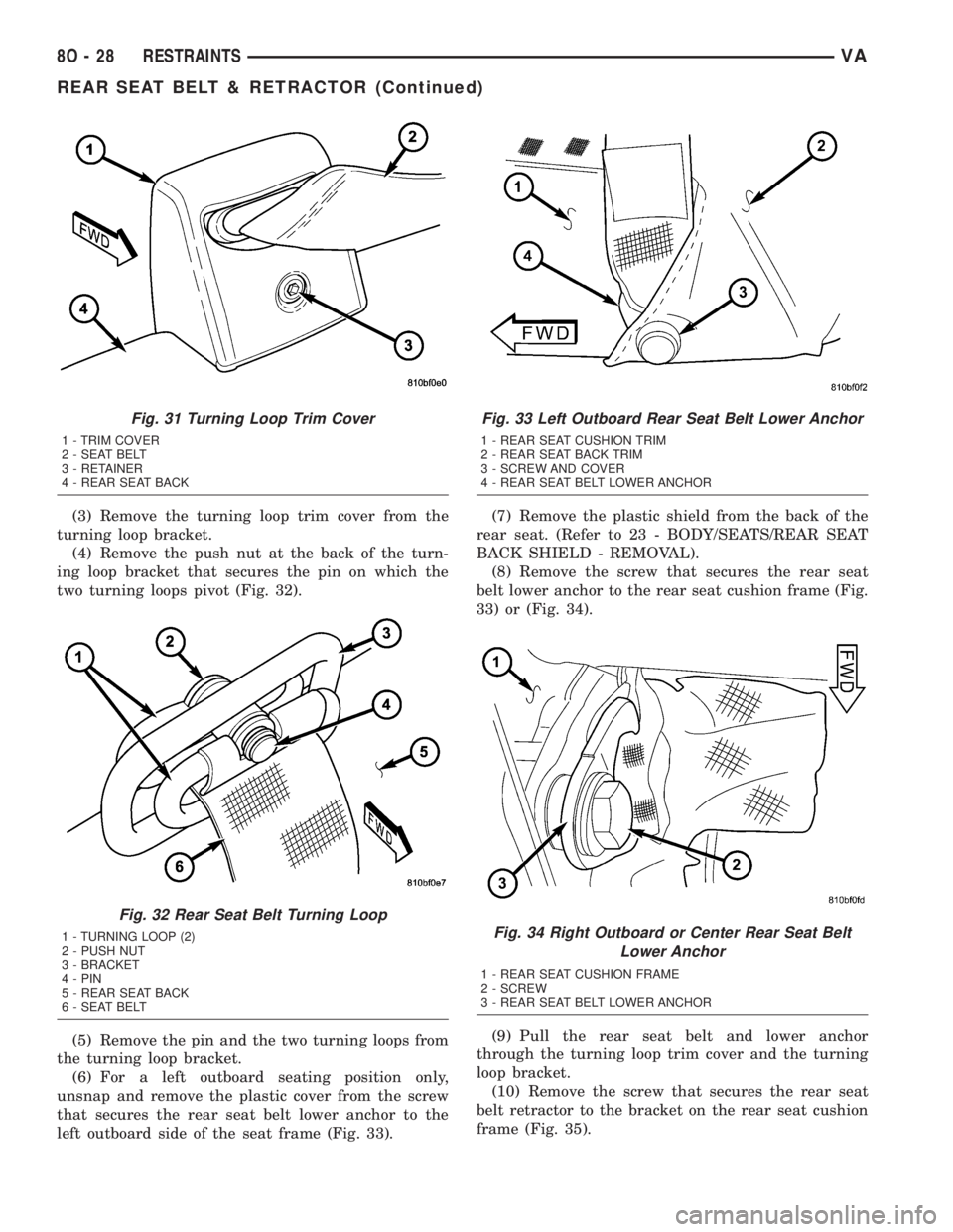
(3) Remove the turning loop trim cover from the
turning loop bracket.
(4) Remove the push nut at the back of the turn-
ing loop bracket that secures the pin on which the
two turning loops pivot (Fig. 32).
(5) Remove the pin and the two turning loops from
the turning loop bracket.
(6) For a left outboard seating position only,
unsnap and remove the plastic cover from the screw
that secures the rear seat belt lower anchor to the
left outboard side of the seat frame (Fig. 33).(7) Remove the plastic shield from the back of the
rear seat. (Refer to 23 - BODY/SEATS/REAR SEAT
BACK SHIELD - REMOVAL).
(8) Remove the screw that secures the rear seat
belt lower anchor to the rear seat cushion frame (Fig.
33) or (Fig. 34).
(9) Pull the rear seat belt and lower anchor
through the turning loop trim cover and the turning
loop bracket.
(10) Remove the screw that secures the rear seat
belt retractor to the bracket on the rear seat cushion
frame (Fig. 35).
Fig. 31 Turning Loop Trim Cover
1 - TRIM COVER
2 - SEAT BELT
3 - RETAINER
4 - REAR SEAT BACK
Fig. 32 Rear Seat Belt Turning Loop
1 - TURNING LOOP (2)
2 - PUSH NUT
3 - BRACKET
4 - PIN
5 - REAR SEAT BACK
6 - SEAT BELT
Fig. 33 Left Outboard Rear Seat Belt Lower Anchor
1 - REAR SEAT CUSHION TRIM
2 - REAR SEAT BACK TRIM
3 - SCREW AND COVER
4 - REAR SEAT BELT LOWER ANCHOR
Fig. 34 Right Outboard or Center Rear Seat Belt
Lower Anchor
1 - REAR SEAT CUSHION FRAME
2 - SCREW
3 - REAR SEAT BELT LOWER ANCHOR
8O - 28 RESTRAINTSVA
REAR SEAT BELT & RETRACTOR (Continued)
Page 267 of 1232
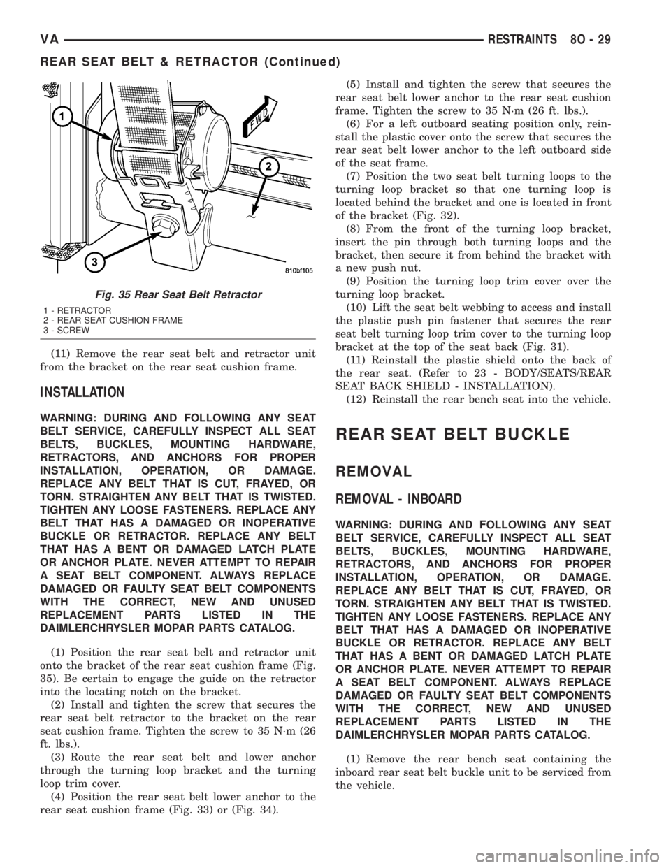
(11) Remove the rear seat belt and retractor unit
from the bracket on the rear seat cushion frame.
INSTALLATION
WARNING: DURING AND FOLLOWING ANY SEAT
BELT SERVICE, CAREFULLY INSPECT ALL SEAT
BELTS, BUCKLES, MOUNTING HARDWARE,
RETRACTORS, AND ANCHORS FOR PROPER
INSTALLATION, OPERATION, OR DAMAGE.
REPLACE ANY BELT THAT IS CUT, FRAYED, OR
TORN. STRAIGHTEN ANY BELT THAT IS TWISTED.
TIGHTEN ANY LOOSE FASTENERS. REPLACE ANY
BELT THAT HAS A DAMAGED OR INOPERATIVE
BUCKLE OR RETRACTOR. REPLACE ANY BELT
THAT HAS A BENT OR DAMAGED LATCH PLATE
OR ANCHOR PLATE. NEVER ATTEMPT TO REPAIR
A SEAT BELT COMPONENT. ALWAYS REPLACE
DAMAGED OR FAULTY SEAT BELT COMPONENTS
WITH THE CORRECT, NEW AND UNUSED
REPLACEMENT PARTS LISTED IN THE
DAIMLERCHRYSLER MOPAR PARTS CATALOG.
(1) Position the rear seat belt and retractor unit
onto the bracket of the rear seat cushion frame (Fig.
35). Be certain to engage the guide on the retractor
into the locating notch on the bracket.
(2) Install and tighten the screw that secures the
rear seat belt retractor to the bracket on the rear
seat cushion frame. Tighten the screw to 35 N´m (26
ft. lbs.).
(3) Route the rear seat belt and lower anchor
through the turning loop bracket and the turning
loop trim cover.
(4) Position the rear seat belt lower anchor to the
rear seat cushion frame (Fig. 33) or (Fig. 34).(5) Install and tighten the screw that secures the
rear seat belt lower anchor to the rear seat cushion
frame. Tighten the screw to 35 N´m (26 ft. lbs.).
(6) For a left outboard seating position only, rein-
stall the plastic cover onto the screw that secures the
rear seat belt lower anchor to the left outboard side
of the seat frame.
(7) Position the two seat belt turning loops to the
turning loop bracket so that one turning loop is
located behind the bracket and one is located in front
of the bracket (Fig. 32).
(8) From the front of the turning loop bracket,
insert the pin through both turning loops and the
bracket, then secure it from behind the bracket with
a new push nut.
(9) Position the turning loop trim cover over the
turning loop bracket.
(10) Lift the seat belt webbing to access and install
the plastic push pin fastener that secures the rear
seat belt turning loop trim cover to the turning loop
bracket at the top of the seat back (Fig. 31).
(11) Reinstall the plastic shield onto the back of
the rear seat. (Refer to 23 - BODY/SEATS/REAR
SEAT BACK SHIELD - INSTALLATION).
(12) Reinstall the rear bench seat into the vehicle.
REAR SEAT BELT BUCKLE
REMOVAL
REMOVAL - INBOARD
WARNING: DURING AND FOLLOWING ANY SEAT
BELT SERVICE, CAREFULLY INSPECT ALL SEAT
BELTS, BUCKLES, MOUNTING HARDWARE,
RETRACTORS, AND ANCHORS FOR PROPER
INSTALLATION, OPERATION, OR DAMAGE.
REPLACE ANY BELT THAT IS CUT, FRAYED, OR
TORN. STRAIGHTEN ANY BELT THAT IS TWISTED.
TIGHTEN ANY LOOSE FASTENERS. REPLACE ANY
BELT THAT HAS A DAMAGED OR INOPERATIVE
BUCKLE OR RETRACTOR. REPLACE ANY BELT
THAT HAS A BENT OR DAMAGED LATCH PLATE
OR ANCHOR PLATE. NEVER ATTEMPT TO REPAIR
A SEAT BELT COMPONENT. ALWAYS REPLACE
DAMAGED OR FAULTY SEAT BELT COMPONENTS
WITH THE CORRECT, NEW AND UNUSED
REPLACEMENT PARTS LISTED IN THE
DAIMLERCHRYSLER MOPAR PARTS CATALOG.
(1) Remove the rear bench seat containing the
inboard rear seat belt buckle unit to be serviced from
the vehicle.
Fig. 35 Rear Seat Belt Retractor
1 - RETRACTOR
2 - REAR SEAT CUSHION FRAME
3 - SCREW
VARESTRAINTS 8O - 29
REAR SEAT BELT & RETRACTOR (Continued)
Page 268 of 1232
(2) Remove the plastic shield from the back of the
rear seat. (Refer to 23 - BODY/SEATS/REAR SEAT
BACK SHIELD - REMOVAL).
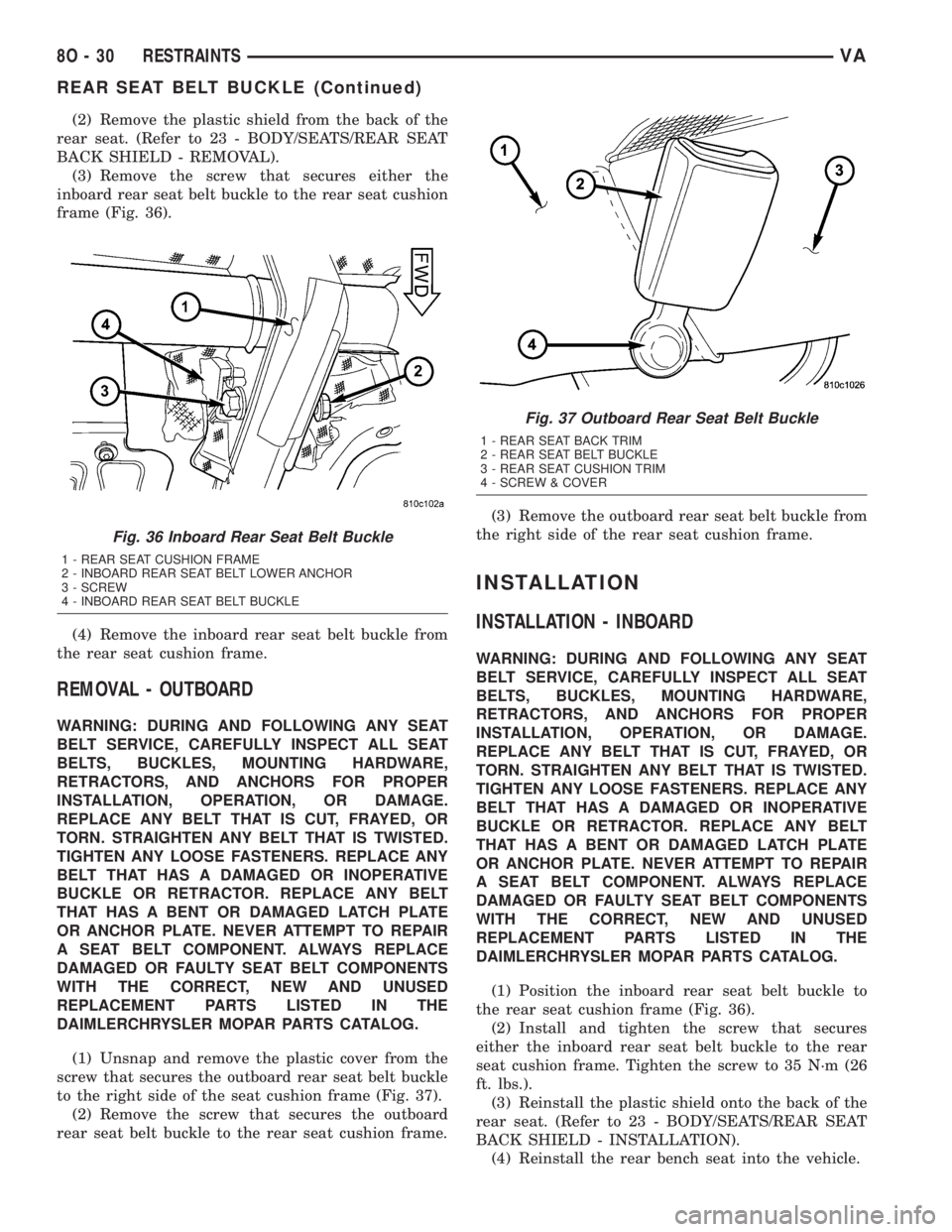
(3) Remove the screw that secures either the
inboard rear seat belt buckle to the rear seat cushion
frame (Fig. 36).
(4) Remove the inboard rear seat belt buckle from
the rear seat cushion frame.
REMOVAL - OUTBOARD
WARNING: DURING AND FOLLOWING ANY SEAT
BELT SERVICE, CAREFULLY INSPECT ALL SEAT
BELTS, BUCKLES, MOUNTING HARDWARE,
RETRACTORS, AND ANCHORS FOR PROPER
INSTALLATION, OPERATION, OR DAMAGE.
REPLACE ANY BELT THAT IS CUT, FRAYED, OR
TORN. STRAIGHTEN ANY BELT THAT IS TWISTED.
TIGHTEN ANY LOOSE FASTENERS. REPLACE ANY
BELT THAT HAS A DAMAGED OR INOPERATIVE
BUCKLE OR RETRACTOR. REPLACE ANY BELT
THAT HAS A BENT OR DAMAGED LATCH PLATE
OR ANCHOR PLATE. NEVER ATTEMPT TO REPAIR
A SEAT BELT COMPONENT. ALWAYS REPLACE
DAMAGED OR FAULTY SEAT BELT COMPONENTS
WITH THE CORRECT, NEW AND UNUSED
REPLACEMENT PARTS LISTED IN THE
DAIMLERCHRYSLER MOPAR PARTS CATALOG.
(1) Unsnap and remove the plastic cover from the
screw that secures the outboard rear seat belt buckle
to the right side of the seat cushion frame (Fig. 37).
(2) Remove the screw that secures the outboard
rear seat belt buckle to the rear seat cushion frame.(3) Remove the outboard rear seat belt buckle from
the right side of the rear seat cushion frame.
INSTALLATION
INSTALLATION - INBOARD
WARNING: DURING AND FOLLOWING ANY SEAT
BELT SERVICE, CAREFULLY INSPECT ALL SEAT
BELTS, BUCKLES, MOUNTING HARDWARE,
RETRACTORS, AND ANCHORS FOR PROPER
INSTALLATION, OPERATION, OR DAMAGE.
REPLACE ANY BELT THAT IS CUT, FRAYED, OR
TORN. STRAIGHTEN ANY BELT THAT IS TWISTED.
TIGHTEN ANY LOOSE FASTENERS. REPLACE ANY
BELT THAT HAS A DAMAGED OR INOPERATIVE
BUCKLE OR RETRACTOR. REPLACE ANY BELT
THAT HAS A BENT OR DAMAGED LATCH PLATE
OR ANCHOR PLATE. NEVER ATTEMPT TO REPAIR
A SEAT BELT COMPONENT. ALWAYS REPLACE
DAMAGED OR FAULTY SEAT BELT COMPONENTS
WITH THE CORRECT, NEW AND UNUSED
REPLACEMENT PARTS LISTED IN THE
DAIMLERCHRYSLER MOPAR PARTS CATALOG.
(1) Position the inboard rear seat belt buckle to
the rear seat cushion frame (Fig. 36).
(2) Install and tighten the screw that secures
either the inboard rear seat belt buckle to the rear
seat cushion frame. Tighten the screw to 35 N´m (26
ft. lbs.).
(3) Reinstall the plastic shield onto the back of the
rear seat. (Refer to 23 - BODY/SEATS/REAR SEAT
BACK SHIELD - INSTALLATION).
(4) Reinstall the rear bench seat into the vehicle.
Fig. 36 Inboard Rear Seat Belt Buckle
1 - REAR SEAT CUSHION FRAME
2 - INBOARD REAR SEAT BELT LOWER ANCHOR
3 - SCREW
4 - INBOARD REAR SEAT BELT BUCKLE
Fig. 37 Outboard Rear Seat Belt Buckle
1 - REAR SEAT BACK TRIM
2 - REAR SEAT BELT BUCKLE
3 - REAR SEAT CUSHION TRIM
4 - SCREW & COVER
8O - 30 RESTRAINTSVA
REAR SEAT BELT BUCKLE (Continued)
Page 289 of 1232
CHECK VALVE
DESCRIPTION
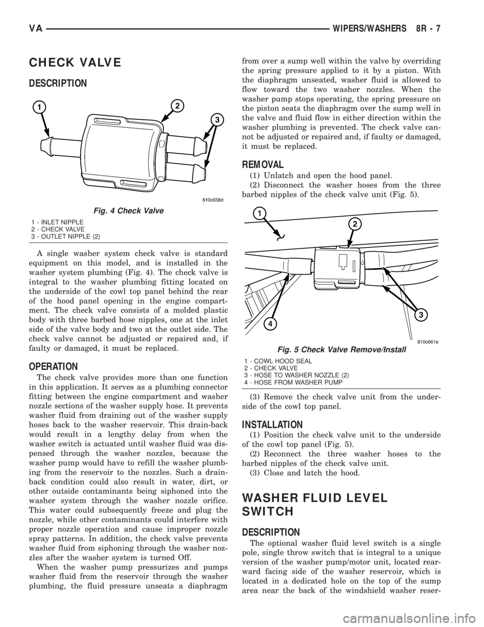
A single washer system check valve is standard
equipment on this model, and is installed in the
washer system plumbing (Fig. 4). The check valve is
integral to the washer plumbing fitting located on
the underside of the cowl top panel behind the rear
of the hood panel opening in the engine compart-
ment. The check valve consists of a molded plastic
body with three barbed hose nipples, one at the inlet
side of the valve body and two at the outlet side. The
check valve cannot be adjusted or repaired and, if
faulty or damaged, it must be replaced.
OPERATION
The check valve provides more than one function
in this application. It serves as a plumbing connector
fitting between the engine compartment and washer
nozzle sections of the washer supply hose. It prevents
washer fluid from draining out of the washer supply
hoses back to the washer reservoir. This drain-back
would result in a lengthy delay from when the
washer switch is actuated until washer fluid was dis-
pensed through the washer nozzles, because the
washer pump would have to refill the washer plumb-
ing from the reservoir to the nozzles. Such a drain-
back condition could also result in water, dirt, or
other outside contaminants being siphoned into the
washer system through the washer nozzle orifice.
This water could subsequently freeze and plug the
nozzle, while other contaminants could interfere with
proper nozzle operation and cause improper nozzle
spray patterns. In addition, the check valve prevents
washer fluid from siphoning through the washer noz-
zles after the washer system is turned Off.
When the washer pump pressurizes and pumps
washer fluid from the reservoir through the washer
plumbing, the fluid pressure unseats a diaphragmfrom over a sump well within the valve by overriding
the spring pressure applied to it by a piston. With
the diaphragm unseated, washer fluid is allowed to
flow toward the two washer nozzles. When the
washer pump stops operating, the spring pressure on
the piston seats the diaphragm over the sump well in
the valve and fluid flow in either direction within the
washer plumbing is prevented. The check valve can-
not be adjusted or repaired and, if faulty or damaged,
it must be replaced.
REMOVAL
(1) Unlatch and open the hood panel.
(2) Disconnect the washer hoses from the three
barbed nipples of the check valve unit (Fig. 5).
(3) Remove the check valve unit from the under-
side of the cowl top panel.
INSTALLATION
(1) Position the check valve unit to the underside
of the cowl top panel (Fig. 5).
(2) Reconnect the three washer hoses to the
barbed nipples of the check valve unit.
(3) Close and latch the hood.
WASHER FLUID LEVEL
SWITCH
DESCRIPTION
The optional washer fluid level switch is a single
pole, single throw switch that is integral to a unique
version of the washer pump/motor unit, located rear-
ward facing side of the washer reservoir, which is
located in a dedicated hole on the top of the sump
area near the back of the windshield washer reser-
Fig. 4 Check Valve
1 - INLET NIPPLE
2 - CHECK VALVE
3 - OUTLET NIPPLE (2)
Fig. 5 Check Valve Remove/Install
1 - COWL HOOD SEAL
2 - CHECK VALVE
3 - HOSE TO WASHER NOZZLE (2)
4 - HOSE FROM WASHER PUMP
VAWIPERS/WASHERS 8R - 7
Page 742 of 1232
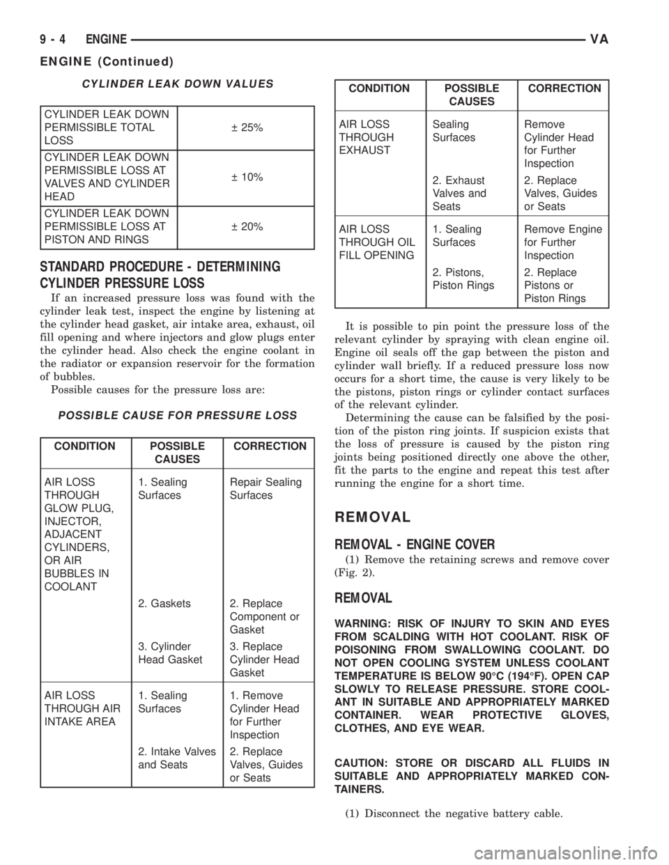
CYLINDER LEAK DOWN VALUES
CYLINDER LEAK DOWN
PERMISSIBLE TOTAL
LOSS 25%
CYLINDER LEAK DOWN
PERMISSIBLE LOSS AT
VALVES AND CYLINDER
HEAD 10%
CYLINDER LEAK DOWN
PERMISSIBLE LOSS AT
PISTON AND RINGS 20%
STANDARD PROCEDURE - DETERMINING
CYLINDER PRESSURE LOSS
If an increased pressure loss was found with the
cylinder leak test, inspect the engine by listening at
the cylinder head gasket, air intake area, exhaust, oil
fill opening and where injectors and glow plugs enter
the cylinder head. Also check the engine coolant in
the radiator or expansion reservoir for the formation
of bubbles.
Possible causes for the pressure loss are:
POSSIBLE CAUSE FOR PRESSURE LOSS
CONDITION POSSIBLE
CAUSESCORRECTION
AIR LOSS
THROUGH
GLOW PLUG,
INJECTOR,
ADJACENT
CYLINDERS,
OR AIR
BUBBLES IN
COOLANT1. Sealing
SurfacesRepair Sealing
Surfaces
2. Gaskets 2. Replace
Component or
Gasket
3. Cylinder
Head Gasket3. Replace
Cylinder Head
Gasket
AIR LOSS
THROUGH AIR
INTAKE AREA1. Sealing
Surfaces1. Remove
Cylinder Head
for Further
Inspection
2. Intake Valves
and Seats2. Replace
Valves, Guides
or Seats
CONDITION POSSIBLE
CAUSESCORRECTION
AIR LOSS
THROUGH
EXHAUSTSealing
SurfacesRemove
Cylinder Head
for Further
Inspection
2. Exhaust
Valves and
Seats2. Replace
Valves, Guides
or Seats
AIR LOSS
THROUGH OIL
FILL OPENING1. Sealing
SurfacesRemove Engine
for Further
Inspection
2. Pistons,
Piston Rings2. Replace
Pistons or
Piston Rings
It is possible to pin point the pressure loss of the
relevant cylinder by spraying with clean engine oil.
Engine oil seals off the gap between the piston and
cylinder wall briefly. If a reduced pressure loss now
occurs for a short time, the cause is very likely to be
the pistons, piston rings or cylinder contact surfaces
of the relevant cylinder.
Determining the cause can be falsified by the posi-
tion of the piston ring joints. If suspicion exists that
the loss of pressure is caused by the piston ring
joints being positioned directly one above the other,
fit the parts to the engine and repeat this test after
running the engine for a short time.
REMOVAL
REMOVAL - ENGINE COVER
(1) Remove the retaining screws and remove cover
(Fig. 2).
REMOVAL
WARNING: RISK OF INJURY TO SKIN AND EYES
FROM SCALDING WITH HOT COOLANT. RISK OF
POISONING FROM SWALLOWING COOLANT. DO
NOT OPEN COOLING SYSTEM UNLESS COOLANT
TEMPERATURE IS BELOW 90ÉC (194ÉF). OPEN CAP
SLOWLY TO RELEASE PRESSURE. STORE COOL-
ANT IN SUITABLE AND APPROPRIATELY MARKED
CONTAINER. WEAR PROTECTIVE GLOVES,
CLOTHES, AND EYE WEAR.
CAUTION: STORE OR DISCARD ALL FLUIDS IN
SUITABLE AND APPROPRIATELY MARKED CON-
TAINERS.
(1) Disconnect the negative battery cable.
9 - 4 ENGINEVA
ENGINE (Continued)
Page 1039 of 1232
BODY
TABLE OF CONTENTS
page page
BODY
WARNING
SAFETY PRECAUTIONS AND WARNINGS . . . 1
DIAGNOSIS AND TESTING
DIAGNOSIS AND TESTING - WATER LEAKS . 1
DIAGNOSIS AND TESTING - WIND NOISE . . . 2
STANDARD PROCEDURE
STANDARD PROCEDURE - PLASTIC BODY
PANEL REPAIR........................3
STANDARD PROCEDURE - BUZZ, SQUEAK
& RATTLE...........................10
SPECIFICATIONS.......................12DOOR - FRONT.........................13
DOORS - REAR.........................24
DOORS - SLIDING.......................36
EXTERIOR.............................47
HOOD.................................50
INSTRUMENT PANEL.....................53
INTERIOR..............................67
PAINT.................................74
SEATS................................76
STATIONARY GLASS.....................81
WEATHERSTRIP/SEALS...................87
BODY STRUCTURE......................88
BODY
WARNING
SAFETY PRECAUTIONS AND WARNINGS
WARNING: USE AN OSHA APPROVED BREATHING
FILTER WHEN SPRAYING PAINT OR SOLVENTS IN
A CONFINED AREA. PERSONAL INJURY CAN
RESULT.
²AVOID PROLONGED SKIN CONTACT WITH
PETROLEUM OR ALCOHOL ± BASED CLEANING
SOLVENTS. PERSONAL INJURY CAN RESULT.
²DO NOT STAND UNDER A HOISTED VEHICLE
THAT IS NOT PROPERLY SUPPORTED ON SAFETY
STANDS. PERSONAL INJURY CAN RESULT.
CAUTION: When holes must be drilled or punched
in an inner body panel, verify depth of space to the
outer body panel, electrical wiring, or other compo-
nents. Damage to vehicle can result.
²Do not weld exterior panels unless combustible
material on the interior of vehicle is removed from
the repair area. Fire or hazardous conditions, can
result.
²Always have a fire extinguisher ready for use
when welding.
²Disconnect the negative (-) cable clamp from
the battery when servicing electrical components
that are live when the ignition is OFF. Damage to
electrical system can result.
²Do not use abrasive chemicals or compounds
on painted surfaces. Damage to finish can result.²Do not use harsh alkaline based cleaning sol-
vents on painted or upholstered surfaces. Damage
to finish or color can result.
²Do not hammer or pound on plastic trim panel
when servicing interior trim. Plastic panels can
break.DIAGNOSIS AND TESTING
DIAGNOSIS AND TESTING - WATER LEAKS
Water leaks can be caused by poor sealing,
improper body component alignment, body seam
porosity, missing plugs, or blocked drain holes. Cen-
trifugal and gravitational force can cause water to
drip from a location away from the actual leak point,
making leak detection difficult. All body sealing
points should be water tight in normal wet-driving
conditions. Water flowing downward from the front of
the vehicle should not enter the passenger or luggage
compartment. Moving sealing surfaces will not
always seal water tight under all conditions. At
times, side glass or door seals will allow water to
enter the passenger compartment during high pres-
sure washing or hard driving rain (severe) condi-
tions. Overcompensating on door or glass
adjustments to stop a water leak that occurs under
severe conditions can cause premature seal wear and
excessive closing or latching effort. After completing
a repair, water test vehicle to verify leak has stopped
before returning vehicle to use.
VABODY 23 - 1
Page 1107 of 1232
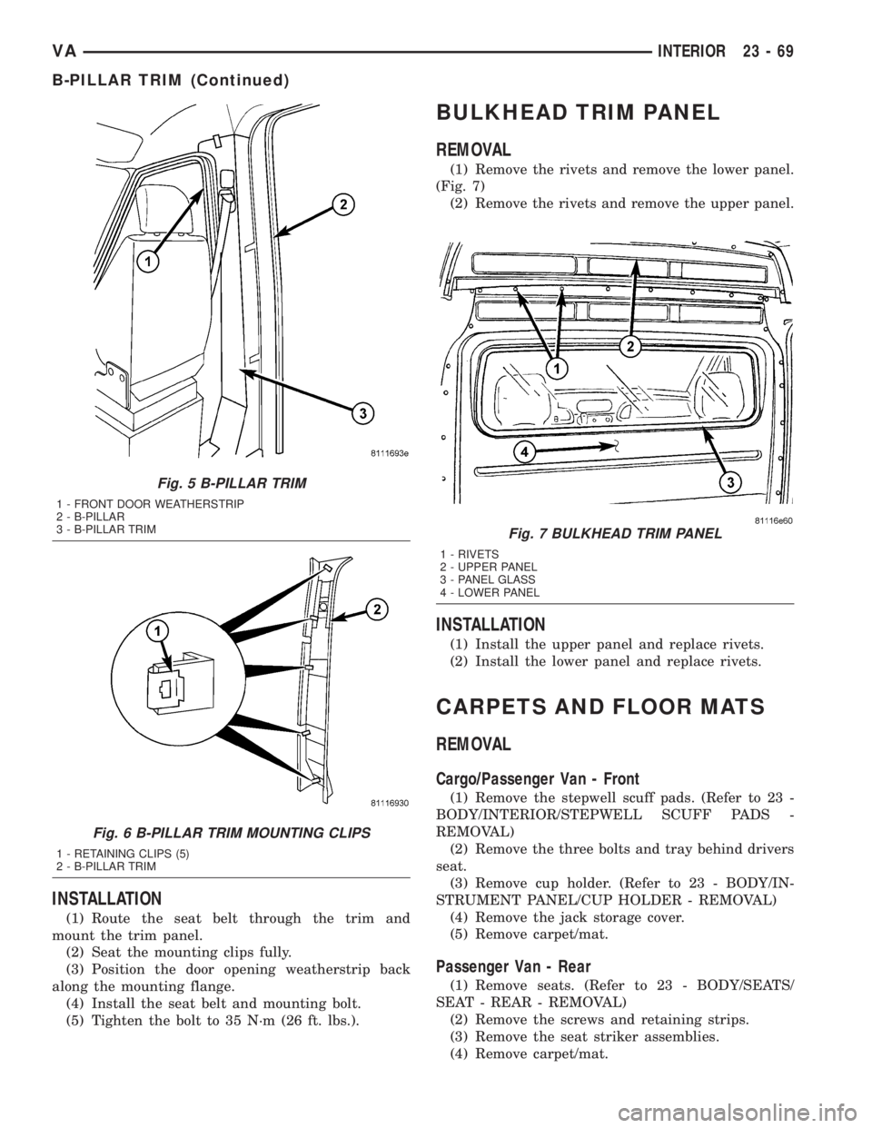
INSTALLATION
(1) Route the seat belt through the trim and
mount the trim panel.
(2) Seat the mounting clips fully.
(3) Position the door opening weatherstrip back
along the mounting flange.
(4) Install the seat belt and mounting bolt.
(5) Tighten the bolt to 35 N´m (26 ft. lbs.).
BULKHEAD TRIM PANEL
REMOVAL
(1) Remove the rivets and remove the lower panel.
(Fig. 7)
(2) Remove the rivets and remove the upper panel.
INSTALLATION
(1) Install the upper panel and replace rivets.
(2) Install the lower panel and replace rivets.
CARPETS AND FLOOR MATS
REMOVAL
Cargo/Passenger Van - Front
(1) Remove the stepwell scuff pads. (Refer to 23 -
BODY/INTERIOR/STEPWELL SCUFF PADS -
REMOVAL)
(2) Remove the three bolts and tray behind drivers
seat.
(3) Remove cup holder. (Refer to 23 - BODY/IN-
STRUMENT PANEL/CUP HOLDER - REMOVAL)
(4) Remove the jack storage cover.
(5) Remove carpet/mat.
Passenger Van - Rear
(1) Remove seats. (Refer to 23 - BODY/SEATS/
SEAT - REAR - REMOVAL)
(2) Remove the screws and retaining strips.
(3) Remove the seat striker assemblies.
(4) Remove carpet/mat.
Fig. 5 B-PILLAR TRIM
1 - FRONT DOOR WEATHERSTRIP
2 - B-PILLAR
3 - B-PILLAR TRIM
Fig. 6 B-PILLAR TRIM MOUNTING CLIPS
1 - RETAINING CLIPS (5)
2 - B-PILLAR TRIM
Fig. 7 BULKHEAD TRIM PANEL
1 - RIVETS
2 - UPPER PANEL
3 - PANEL GLASS
4 - LOWER PANEL
VAINTERIOR 23 - 69
B-PILLAR TRIM (Continued)